EP0541098A1 - Manual transmission for vehicle - Google Patents
Manual transmission for vehicle Download PDFInfo
- Publication number
- EP0541098A1 EP0541098A1 EP92118989A EP92118989A EP0541098A1 EP 0541098 A1 EP0541098 A1 EP 0541098A1 EP 92118989 A EP92118989 A EP 92118989A EP 92118989 A EP92118989 A EP 92118989A EP 0541098 A1 EP0541098 A1 EP 0541098A1
- Authority
- EP
- European Patent Office
- Prior art keywords
- shift
- restraining member
- restraining
- movement
- reverse
- Prior art date
- Legal status (The legal status is an assumption and is not a legal conclusion. Google has not performed a legal analysis and makes no representation as to the accuracy of the status listed.)
- Granted
Links
- 230000005540 biological transmission Effects 0.000 title claims abstract description 28
- 230000000452 restraining effect Effects 0.000 claims abstract description 121
- 230000002441 reversible effect Effects 0.000 claims abstract description 67
- 230000008859 change Effects 0.000 claims abstract description 56
- 230000009471 action Effects 0.000 claims description 2
- 230000007246 mechanism Effects 0.000 description 8
- 230000008878 coupling Effects 0.000 description 5
- 238000010168 coupling process Methods 0.000 description 5
- 238000005859 coupling reaction Methods 0.000 description 5
- 230000007935 neutral effect Effects 0.000 description 4
- 210000000078 claw Anatomy 0.000 description 3
- 238000005192 partition Methods 0.000 description 3
- 238000010586 diagram Methods 0.000 description 2
- 238000010276 construction Methods 0.000 description 1
- 230000002708 enhancing effect Effects 0.000 description 1
- 230000002401 inhibitory effect Effects 0.000 description 1
- 230000004048 modification Effects 0.000 description 1
- 238000012986 modification Methods 0.000 description 1
- 230000002829 reductive effect Effects 0.000 description 1
- 230000000717 retained effect Effects 0.000 description 1
- 230000000630 rising effect Effects 0.000 description 1
Images




Classifications
-
- F—MECHANICAL ENGINEERING; LIGHTING; HEATING; WEAPONS; BLASTING
- F16—ENGINEERING ELEMENTS AND UNITS; GENERAL MEASURES FOR PRODUCING AND MAINTAINING EFFECTIVE FUNCTIONING OF MACHINES OR INSTALLATIONS; THERMAL INSULATION IN GENERAL
- F16H—GEARING
- F16H63/00—Control outputs from the control unit to change-speed- or reversing-gearings for conveying rotary motion or to other devices than the final output mechanism
- F16H63/02—Final output mechanisms therefor; Actuating means for the final output mechanisms
- F16H63/30—Constructional features of the final output mechanisms
- F16H63/302—Final output mechanisms for reversing
-
- F—MECHANICAL ENGINEERING; LIGHTING; HEATING; WEAPONS; BLASTING
- F16—ENGINEERING ELEMENTS AND UNITS; GENERAL MEASURES FOR PRODUCING AND MAINTAINING EFFECTIVE FUNCTIONING OF MACHINES OR INSTALLATIONS; THERMAL INSULATION IN GENERAL
- F16H—GEARING
- F16H61/00—Control functions within control units of change-speed- or reversing-gearings for conveying rotary motion ; Control of exclusively fluid gearing, friction gearing, gearings with endless flexible members or other particular types of gearing
- F16H61/16—Inhibiting or initiating shift during unfavourable conditions , e.g. preventing forward-reverse shift at high vehicle speed, preventing engine overspeed
-
- F—MECHANICAL ENGINEERING; LIGHTING; HEATING; WEAPONS; BLASTING
- F16—ENGINEERING ELEMENTS AND UNITS; GENERAL MEASURES FOR PRODUCING AND MAINTAINING EFFECTIVE FUNCTIONING OF MACHINES OR INSTALLATIONS; THERMAL INSULATION IN GENERAL
- F16H—GEARING
- F16H61/00—Control functions within control units of change-speed- or reversing-gearings for conveying rotary motion ; Control of exclusively fluid gearing, friction gearing, gearings with endless flexible members or other particular types of gearing
- F16H61/18—Preventing unintentional or unsafe shift, e.g. preventing manual shift from highest gear to reverse gear
- F16H2061/185—Means, e.g. catches or interlocks, for preventing unintended shift into reverse gear
-
- F—MECHANICAL ENGINEERING; LIGHTING; HEATING; WEAPONS; BLASTING
- F16—ENGINEERING ELEMENTS AND UNITS; GENERAL MEASURES FOR PRODUCING AND MAINTAINING EFFECTIVE FUNCTIONING OF MACHINES OR INSTALLATIONS; THERMAL INSULATION IN GENERAL
- F16H—GEARING
- F16H63/00—Control outputs from the control unit to change-speed- or reversing-gearings for conveying rotary motion or to other devices than the final output mechanism
- F16H63/02—Final output mechanisms therefor; Actuating means for the final output mechanisms
- F16H63/30—Constructional features of the final output mechanisms
- F16H63/34—Locking or disabling mechanisms
- F16H63/3408—Locking or disabling mechanisms the locking mechanism being moved by the final actuating mechanism
-
- F—MECHANICAL ENGINEERING; LIGHTING; HEATING; WEAPONS; BLASTING
- F16—ENGINEERING ELEMENTS AND UNITS; GENERAL MEASURES FOR PRODUCING AND MAINTAINING EFFECTIVE FUNCTIONING OF MACHINES OR INSTALLATIONS; THERMAL INSULATION IN GENERAL
- F16H—GEARING
- F16H63/00—Control outputs from the control unit to change-speed- or reversing-gearings for conveying rotary motion or to other devices than the final output mechanism
- F16H63/02—Final output mechanisms therefor; Actuating means for the final output mechanisms
- F16H63/30—Constructional features of the final output mechanisms
- F16H63/38—Detents
-
- Y—GENERAL TAGGING OF NEW TECHNOLOGICAL DEVELOPMENTS; GENERAL TAGGING OF CROSS-SECTIONAL TECHNOLOGIES SPANNING OVER SEVERAL SECTIONS OF THE IPC; TECHNICAL SUBJECTS COVERED BY FORMER USPC CROSS-REFERENCE ART COLLECTIONS [XRACs] AND DIGESTS
- Y10—TECHNICAL SUBJECTS COVERED BY FORMER USPC
- Y10T—TECHNICAL SUBJECTS COVERED BY FORMER US CLASSIFICATION
- Y10T74/00—Machine element or mechanism
- Y10T74/20—Control lever and linkage systems
- Y10T74/20012—Multiple controlled elements
- Y10T74/20018—Transmission control
- Y10T74/20085—Restriction of shift, gear selection, or gear engagement
Definitions
- the present invention relates to a manual transmission for vehicles, in which any one of a plurality of forward shift stages and a reverse shift stage can, selectively, be established by movement of a shift member operatively associated with the selecting and shifting operations of a change lever, and the shift member is restrained from moving to a position in which the reverse shift stage is established, by the abutment of the shift member against an engage position provided on a restraining member connected to a drive means and adapted to be moved from an inoperative position to an operative position during forward travelling of the vehicle.
- a manual transmission for a vehicle in which any one of a plurality of forward shift stages and a reverse shift stage can selectively be established by movement of a shift member operatively associated with the selecting and shifting operations of a change lever.
- the shift member is restrained from moving to a position in which the reverse shift stage is established, by the abutment of the shift member against an engage portion provided on a restraining member which is connected to a drive means and moved from an inoperative position to an operative position during forward travelling of the vehicle.
- the restraining member is provided with an abutment portion against which the shift member is abutable, and the abutment portion is urged by a movement of the shift member operatively associated with the operation of the change lever, thereby forcedly returning the restraining member from the operative position to the inoperative position.
- the abutment portion of the restraining member can be urged by the shift member by moving the shift member by means of the change lever, thereby returning the restraining member to the inoperative position to establish the reverse shift stage.
- a manual transmission for a vehicle wherein the restraining member is pivotally supported to a fixing portion through a pivot, and a line of action of a load received by the engage portion of the restraining member from the the shift member passes through the pivot.
- a manual transmission for a vehicle wherein the restraining member is forcedly returned from the operative position to the inoperative position by movement of the shift member operatively associated with the shifting operation of the change lever to a predetermined forward shift stage.
- a manual transmission for a vehicle wherein the restraining member is forcedly returned from the operative position to the inoperative position by movement of the shift member operatively associated with the shifting operation of the change lever to a predetermined forward shift stage.
- a manual transmission for a vehicle wherein the restraining member is bent into a U-shape surrounding a group of loci of movement of the shift member in accordance with the shifting operation, the loci being located on a side of a locus of movement of the shift member in accordance with the selecting operation, the restraining member being pivotally supported at one end on the pivot and being provided at an inner side of the other end with the engage portion.
- the restraining member is compactly formed, thereby reducing a space for location.
- a manual tansmission for a vehicle wherein an extension is provided on the other end so as to extend in an opposite direction from the pivot with respect to the engage portion, a tip end of the extension being connected to the drive means, the drive means being disposed in a space defined between the extension and an outer side of the U-shape restraining member.
- a space defined between the extension and an outer side of the U-shape restraining member can effectively utilized, thereby reducing a space for location.
- a transmission M for a vehicle includes six forward shift stages and one reverse shift stage.
- the transmission M comprises an input shaft Ms connected, in series, to an engine E through a clutch C, and an output shaft Cs, a reverse idle shaft Rs and a final shaft Fs disposed in parallel to the input shaft Ms.
- a main first-shift gear 1 is fixedly mounted on the input shaft Ms and meshed with a counter first-shift gear 2 which is relatively rotatably carried on the output shaft Cs.
- a first shift stage is established by coupling the counter first-shift gear 2 to the output shaft Cs by means of a sleeve 4 of a first-second shift synchronization mechanism driven by a first-second shift fork 3.
- a main first-shift gear 5 is fixedly mounted on the input shaft Ms and meshed with a counter second-shift gear 6 which is relatively rotatably carried on the output shaft Cs.
- a second shift stage is established by coupling the counter second-shift gear 6 to the output shaft Cs by means of the sleeve 4.
- a main third-shift gear 7 is relatively rotatably carried on the input shaft Ms and meshed with a counter third-shift gear 8 which is fixedly mounted on the output shaft Cs.
- a third shift stage is established by coupling the main third-shift gear 7 to the input shaft Ms by means of a sleeve 10 of a third-fourth shift synchronization mechanism which is driven by a third-fourth shift fork 9.
- a main fourth-shift gear 11 is relatively rotatably carried on the input shaft Ms and meshed with a counter fourth-shift gear 12 which is fixedly mounted on the output shaft Cs.
- a fourth shift stage is established by coupling the main fourth-shift gear 11 to the input shaft Ms by the sleeve 10.
- a main fifth-shift gear 13 and a main sixth-shift gear 14 are relatively rotatably carried on the input shaft Ms.
- the main fifth-shift gear 13 and the sixth-shift gear 14 are meshed with a counter fifth-shift gear 15 and a counter sixth-shift gear 16 both fixedly mounted on the output shaft Cs, respectively.
- a fifth shift and a sixth shift are established by selectively coupling the main fifth-shift gear 13 and the main sixth-shift gear 14 to the input shaft Ms by means of a sleeve 18 of a third-fourth synchronization mechanism which is driven by a fifth-sixth shift fork 17.
- a first 19 and a second reverse idle gear 20 are relatively rotatably carried on the reverse idle shaft Rs.
- the first reverse idle gear 19 is meshed with a reverse drive gear 21 which is fixedly mounted on the input shaft Ms.
- the second reverse idle gear 20 is meshed with a reverse driven gear 22 which is fixedly mounted on the output shaft Cs.
- a reverse-shift stage is established by sliding a sleeve 24 of a reverse synchronization mechanism by means of a reverse shift fork 23 to integrally couple the first and second reverse idle gears 19 and 20 with each other.
- the rotation of the input shaft Ms is transmitted to the output shaft Cs by any of the first to sixth shift stages and the reverse shift stage, and further, the rotation of the output shaft Cs is transmitted through the final drive gear 25 and the final driven gear 26 to the final shaft Fs.
- the input shaft Ms, the output shaft Cs and the final shaft Fs are disposed sequentially from a left and upper position to a right and lower position within a transmission case 27, and the reverse idle shaft Rs is disposed at a position rightward of and above the input shaft Ms.
- a first-second shift rod 28 supporting the first-second shift fork 3 a third-fourth shift rod 29 supporting the third-fourth shift fork 9
- a fifth-sixth shift rod 30 supporting the fifth-sixth shift fork 17 and a first reverse shift rod 31 are disposed in parallel to one another at positions leftward of the input shaft Ms and the output shaft Cs.
- a shift change mechanism S is provided leftward of the four rods 28, 29, 30 and 31.
- a change rod 34 connected to a change lever is axially slidably and rotatably supported between a partition wall 32 of the transmission case 27 and a shift box 33 fixed to the partition wall 32.
- a neutral position of the change rod 34 and two shift positions thereof on the opposite side of the neutral position are restrained by a detent mechanism 35.
- N designates a neutral position
- 1 designates a first-shift position
- 2 designates a second-shift position
- 3 designates a third-shift position
- 4 designates a fourth-shift position
- 6 designates a sixth-shift position
- R designates a reverse position.
- a swingable member 37, Fig.3, is pivotally mounted to a pivot 36 which is fixedly mounted in the shift box 33, Fig.4, in parallel to the change rod 34.
- An operating arm 38 is secured to the change rod 34.
- a pin 40 is fixedly mounted to the swingable member 37 to engage two rollers 39, Fig.3, mounted at a tip end of the operating arm 38.
- a shift arm 42 is axially slidably and rotatably carried on the pivot 36.
- An elongaged hole 37a is provided in the swingable member 37 to extend axially of the pivot 36, and a drive projection 42a of the shift arm 42 extends through the elongated hole 37a to the outside.
- Engage grooves 43a to 46a, Fig.3 are formed in shift pieces 43 to 46 secured to the four shift rods 28 to 31 and are disposed on a locus of swinging movement of a tip end of the drive projection 42a of the shift arm 42.
- the stop position of the swingable member 37 and, thus, the stop position of the shift arm 42 is restrained to a position in which the drive projection 42a of the shift arm 42 engages the engage groove 44a in the third-fourth shift piece 44, by biasing the pin 40 by a resilient force of a spring 47, Fig.4.
- a circumferentially extending elongated groove 38a is provided in a boss portion of the operating arm 38 secured to the change rod 34, Fig.4.
- a circumferentially extending elongated groove 42b is provided in a boss portion of the shift arm 42.
- Two pins 51 and 52 are embedded in opposite ends of a lever 50 which is pivotally supported at its intermediate portion by the pivot 49 on a bracket 48 rising on the shift box 33. The two pins 51 and 52 engaged in the elongated grooves 38a and 42b, respectively.
- the shift arm 42 with the elongated groove 42b urged on the other pin 52 slides in a direction reverse from the direction of sliding movement of the change rod 34, while being guided on the pivot 36 and in the elongated hole 37a in the swingable member 37.
- the swingable member 37 is provided with a pair of arcuately curved restraining claws 37b and 37c.
- the tip end of the drive projection 42a of the shift arm 42 is disposed between opposed tip ends of the restraining claws 37b and 37c.
- the restraining claws 37b and 37c are engaged in the engage grooves 43a, 45a and 46a in the first-second shift piece 43, the fifth-sixth shift piece 45 and the reverse shift piece 46, but not the third-fourth shift piece 44, thereby preventing the inadvertent or accidental operation of the three shift pieces 43, 45 and 46.
- the reverse shift piece 46 fixed to the first reverse shift rod 31, is prevented from being rotated by bringing its detent portion 46b into engagement with the adjacent fifth-sixth shift rod 30 for sliding movement.
- a second reverse shift rod 53 having a reverse shift fork 23 is supported on an upper portion of the transmission case 27. Fig.2. in parallel to the first reverse shift rod 31.
- a lever 56, Figs.2 and 5, is pivotally supported at its intermediate portion on a bracket 54 which is mounted on the partition wall 32 through the pivot 55. Opposite ends of the lever 56 are engaged in the engage groove 46c formed in the reverse shift piece 46 and the engage groove 23a formed in the reverse shift fork 23, respectively.
- a restraining member 58 comprising a substantially U-shaped curved plate, with an extension at a tip end, is pivotally mounted at its base end on a bracket 57 on the shift box 33 through the pivot 59.
- the shift box 33 is provided with a cup-shaped cylinder 60 opened at one end.
- a piston 61 is slidably received in the cylinder 60.
- a tip end of the restraining member 58 is opposed to that end face of the piston 61 which is exposed from an opening of the cylinder 60.
- the tip end of the restraining member 58 is biased in a direction of abutment against the piston 61 by means of a spring 62 mounted between the restraining member 58 and the bracket 57.
- a hydraulic pressure is applied, from an oil pump 64 (see Fig.2) connected to the output shaft Cs, through an oil passage 63 into the cylinder 60.
- this hydraulic pressure overcomes a resilient force of the spring 62, the piston 61 is advanced, causing the restraining member 58 to be swung from an inoperative position shown in Fig.7 to an operative position shown in Fig.8.
- the piston 61 is retreated by the resilient force of the spring 62, thereby permitting the restraining member 58 to be returned from the operative position shown in Fig.8 to the inoperative position shown in Fig.7.
- the shift arm 42 includes a restraining projection 42c protruding to an opposite side from the drive projection 42a, as can be seen from Fig.3.
- the restraining projection 42c protrudes in a plane of swinging movement of the restraining member 58 and is adapted to move along a select line L, which connects the following positions: a 1- 2 select position, a 3- 4 select position, a 5- 6 select position and a reverse select position in operative association with the selecting operation of the change lever.
- the restraining projection 42c is adapted to move perpendicularly to the select line L1 toward the 1 to 6 shift positions and the reverse shift position in operative association with the shifting operation of the change lever.
- the select line L1 is established on a straight line passing through pivot 59 of restraining member 58.
- the restraining member 58 is provided, at in inner side of the tip end of the U-shaped plate, with an engage portion 58a which is adapted to engage the restraining projection 42c to prevent the shift arm 42 from moving from the 5- 6 select position to the reverse select position, when the restraining member 58 is in the operative position.
- a face of abutment between the restraining projection 42c and the engage portion 58a is formed at a right angle with respect to the select line L1, and the direction of a load F, received by the engage portion 58a from the restraining projection 42c, coincides with the select line L1.
- the restraining member 58 is also formed with a cam portion 58b which is adapted to be engaged by the restraining member 42c, when the shift arm 42 has been shifted to the 1 shift position.
- the change lever is selectingly operated in the direction of A from the neutral position (the 3- 4 select position) shown in Fig.6, and is, e.g., moved to the 1- 2 select position
- the change rod 34, Fig. 4 operatively associated with the change lever, is rotated and the swingable member 37, with the pin 40 urged by the operating arm 38, is swung about the pivot 36.
- the shift arm 42 engaging the elongated hole 37a, in the swingable member 37 is swung about the pivot 36 in unison with the swingable member 37.
- the drive projection 42a of the shift arm 42. Fig.3 is engaged into the engage groove 43a in the first-second shift piece 43 mounted on the first-second shift rod 28.
- the change lever If the change lever is shiftingly operated from this condition toward the direction of B in Fig.6, for example, into the 1 shift position or the 2 shift position, the change rod 34 slides axially in Fig.4.
- the sliding movement of the change rod 34 is transmitted, through the lever 50, to the shift arm 42 to slide the shift arm 42 along the pivot 36.
- the first-second shift piece 43 engaging the drive projection 42a of the shift arm 28, slides in a direction perpendicular to the sheet of Fig.3, along with the first-second shift rod 28, causing the first or second shift stage to be established by the first-second shift fork 3 mounted on the first-second shift rod 28.
- the change lever is shifted into the 3 or 4 shift position, after selecting operation thereof to the 3- 4 select position, the third or fourth shift stage is established. If the change lever is shifted into the 5 or 6 shift position, after selecting operation thereof to the 5- 6 select position, the fifth or sixth shift stage is established.
- the drive projection 42a of the shift arm 42 is brought into engagement with the reverse shift piece 46 in Fig.3. If the change lever is shifted from this condition into the reverse shift position, the reverse shift piece 46 slides in the leftward direction, as viewed in Fig.5, along with the first reverse shift rod 31. As a result, the second reverse shift rod 53 connected through the lever 56 to the first reverse shift rod 31, slides in a rightward direction along with the reverse shift fork 23, thereby establishing the reverse shift stage.
- the restraining projection 42c provided on the shift arm 42 is moved according to the pattern shown in Fig.6.
- the oil pressure acting on the cylinder 60 is low, and the restraining member 58 is maintained at the inoperative position, shown in Fig.7, by the resilient force of the spring 62. Therefore, the restraining projection 42c can be freely moved to any of the 1 to 6 shift positions and the reverse shift position without interference with the restraining member 58.
- the select line L1 lies on the straight line passing through the pivot 59, and the restraining projection 42c and the engage portion 58a abut against each other in a plane perpendicular to the select line L1.
- the direction of a load F, received by the engage portion 58a of the restraining member 58 from the restraining projection 42c, is in a direction of the select line L1, i.e., is on the line passing through the pivot 59 of the restraining member 58, and such load F cannot produce a rotation moment on the restraining member 58. Therefore, the load F applies no load to the cylinder 60 and the piston 61, and cannot exert any influence to the durability of the cylinder 60 and the piston 61.
- the restraining member 58 is retained at the operative position, thereby making it impossible to establish the reverse shift stage.
- the change lever is shiftingly operated to the 1 shift position, after selecting operation thereof to the 1- 2 select position shown in Fig.6, the restraining projection 42c is moved from the 1- 2 select position shown in Fig.8 to the 1 shift position and, in the course of this movement, the projection 42c abuts against the cam portion 58b of the restraining member 58.
- the restraining member 58 is forcedly swung from the operative position shown in Fig.8 toward the inoperative position shown in Fig.7, thereby making it possible again to establish the reverse shift stage.
- the restraining member 58 is formed in a U-shape surrounding the 1, 3 and 5 shift positions, this contributes to reducing space for location of the restraining member 58. Further, the cylinder 60 of the drive means is disposed in a space between the extension and an outer side of the U-shaped restraining member, thereby leading to a further compact arrangement.
- Figs.9 and 10 illustrate a second embodiment of the present invention.
- a feature of this embodiment is the shape of a cam portion 58c of a restraining member 58 which is different from the shape of the cam portion 58b in the previously-described first embodiment.
- Other portions of the cconstruction are the same as those of the first embodiment.
- the cam portion 58c can be urged by the restraining projection 42c only by moving the restraining projection 42c toward a 1- 2 select position along a select line L2, whereby the restraining member 58 can be returned to an inoperative position shown in Fig.9.
- Fig.11 illustrates a third embodiment of the present invention.
- This embodiment is applied to a manual transmission in which forward shift stages and a reverse shift stage are provided in correspondence to the same select position, such as a manual transmission having five forward shift stages and a reverse shift stage.
- a hydraulic pressure is applied to the cylinder 60 to swing the restraining member 58 by the piston 61 to an operative position shown by a solid line in Fig.11, the restraining projection 42c can be prevented by the engage portion 58a of the restraining member 58 from being moved on a shift line L3 to a reverse shift position, thereby inhibiting the establishment of the reverse shift stage.
- the shift line L3 lies on a straight line passing through the pivot 59, and the restraining projection 42c and the engage portion 58a abut against each other in a plane perpendicular to the shift line L3.
- the direction of a load F received by the engage portion 58a from the restraining projection 42c lies on the straight line passing through the pivot 59. This ensures that a rotation moment can be prevented from being generated on the restraining member 58 by the load F, and the load of the cylinder 60 and the piston 61 can be reduced.
- the restraining member 58 can be returned to an inoperative position, shown by a dashed line in Fig.11, by operating the restraining projection 42c directly to a 5 shift position along the shift line L3 by means of the change lever to urge a cam portion 58d of the restraining member 58 by the restraining projection 42c.
- the restraining projection 42c of the shift arm 42 when the restraining projection 42c of the shift arm 42 is brought into abutment against the engage portion 58a of the restraining member 58, the restraining projection 42c is moved on the straight line passing through the pivot 59 of the restraining member 58 (namely, on the select lines L1 and L2 in the first and second embodiments, and on the shift line L3 in the third embodiment), but the restraining projection 42c is not necessarily required to move on the straight line passing through the pivot 59.
Landscapes
- Engineering & Computer Science (AREA)
- General Engineering & Computer Science (AREA)
- Mechanical Engineering (AREA)
- Gear-Shifting Mechanisms (AREA)
Abstract
Description
- The present invention relates to a manual transmission for vehicles, in which any one of a plurality of forward shift stages and a reverse shift stage can, selectively, be established by movement of a shift member operatively associated with the selecting and shifting operations of a change lever, and the shift member is restrained from moving to a position in which the reverse shift stage is established, by the abutment of the shift member against an engage position provided on a restraining member connected to a drive means and adapted to be moved from an inoperative position to an operative position during forward travelling of the vehicle.
- There is known a conventional manual transmission capable of selectively establishing any one of a plurality of forward shift stages and a reverse shift stage, wherein the movement of a shift member for establishing a reverse shift stage is restrained by a restraining member in order to prevent the accidental or inadvertent shifting to the reverse shift stage during a forward travelling of a vehicle (for example, see Japanese Patent Application Laid-open Nos. 25555/89 and 65753/90).
- In the manual transmission described in the above-described Japanese Patent Application Laid-open No. 25555/89, if the vehicle speed exceeds a predetermined speed, a solenoid is energized, so that the restraining member protrudes to restrain the shift member from moving in a direction to establish the reverse shift stage. However, such restraining member is the output shaft itself of the solenoid and hence, a load from the shift member acts directly on the solenoid, and may shorten the durability of the solenoid.
- In the manual transmission described in the above-described Japanese Patent Application Laid-open No. 65753/90, a hydraulic pressure developed in accordance with an increase in vehicle speed causes a cylinder to be operated, so that a restraining member, comprising a piston slidably received in the cylinder, is brought into engagement in a groove provided in the shift member. Even in this case, however, a load from the shift member acts directly on the piston, which may shorten the durability of the piston.
- Any of the above prior art transmissions is accompanied by a problem that if a trouble is generated in the solenoid or a hydraulic system by the load, or the like received from the shift member, causing the restraining member to stick at an operative position, the movement of the shift member is restrained by the restraining member, resulting in an inability of shifting to the reverse shift stage.
- It is an object of the present invention to reduce the load acting on the drive means for the restraining member to enhance the durability of the drive means, and to enable the reverse shift stage to be established, even if the restraining member should be stuck.
- To achieve the above object, according to a first feature of the present invention, there is provided a manual transmission for a vehicle, in which any one of a plurality of forward shift stages and a reverse shift stage can selectively be established by movement of a shift member operatively associated with the selecting and shifting operations of a change lever. The shift member is restrained from moving to a position in which the reverse shift stage is established, by the abutment of the shift member against an engage portion provided on a restraining member which is connected to a drive means and moved from an inoperative position to an operative position during forward travelling of the vehicle. The restraining member is provided with an abutment portion against which the shift member is abutable, and the abutment portion is urged by a movement of the shift member operatively associated with the operation of the change lever, thereby forcedly returning the restraining member from the operative position to the inoperative position.
- With the first feature of the present invention, when the restraining member has been stuck at the operative position for any reason, the abutment portion of the restraining member can be urged by the shift member by moving the shift member by means of the change lever, thereby returning the restraining member to the inoperative position to establish the reverse shift stage.
- According to a second feature, in addition to the first feature, there is provided a manual transmission for a vehicle, wherein the restraining member is pivotally supported to a fixing portion through a pivot, and a line of action of a load received by the engage portion of the restraining member from the the shift member passes through the pivot.
- With the second feature, in restraining the establishment of the reverse shift stage by pivotally moving the restraining member about the pivot by the drive means to bring the shift member into abutment aginst the restraining member, no rotation moment acts on the restraining member, because the direction of the load, received by the engage portion of the restraining member from the shift member passes through the pivot. As a result, a burden can be prevented from being applied to the drive means of the restraining member by such load, thereby enhancing the durability of the drive means.
- According to a third feature, in addition to the first or second feature, there is provided a manual transmission for a vehicle, wherein the restraining member is forcedly returned from the operative position to the inoperative position by movement of the shift member operatively associated with the shifting operation of the change lever to a predetermined forward shift stage.
- With the third feature, when the restraining member has been stuck at thoperative position for any reason, it is possible to return the restraining member to the inoperative position only by a shifting operation of the change lever to a predetermined forward shift stage.
- According to a fourth feature, in addition to the first or second feature, there is provided a manual transmission for a vehicle, wherein the restraining member is forcedly returned from the operative position to the inoperative position by movement of the shift member operatively associated with the shifting operation of the change lever to a predetermined forward shift stage.
- With the fourth feature, when the restraining member has been stuck at thoperative position for any reason, it is possible to return the restraining member to the inoperative position only by a selecting operation of the change lever to a predetermined forward shift stage.
- According to a fifth feature, in addition to the third or fourth feature, there is provided a manual transmission for a vehicle, wherein the restraining member is bent into a U-shape surrounding a group of loci of movement of the shift member in accordance with the shifting operation, the loci being located on a side of a locus of movement of the shift member in accordance with the selecting operation, the restraining member being pivotally supported at one end on the pivot and being provided at an inner side of the other end with the engage portion.
- With the fifth feature, the restraining member is compactly formed, thereby reducing a space for location.
- According to a sixth feature, in addition to the fifth feature, there is provided a manual tansmission for a vehicle, wherein an extension is provided on the other end so as to extend in an opposite direction from the pivot with respect to the engage portion, a tip end of the extension being connected to the drive means, the drive means being disposed in a space defined between the extension and an outer side of the U-shape restraining member.
- With the sixth feature, a space defined between the extension and an outer side of the U-shape restraining member can effectively utilized, thereby reducing a space for location.
- According to a seventh feature, in addition to the first or second feature, there is provided a manual transmission for a vehicle, wherein the change lever has a shift position for a predetermined forward shift stage and a shift position for the reverse shift stage on the same shift operation line, and the restraining member is forcedly returned from the operative position to the inoperative position by movement of the shift member operatively associated with the shifting operation of the change lever to the predetermined forward shift stage.
- With the seventh feature, when the restraining member has been stuck at the operative position and a reverse shift stage can not be established, it is possible to return the restraining member to the inoperative position only by moving the change lever in the opposite direction to shift it to a predetermined forward shift stage on the same shift operation line as the reverse shift stage.
- The above and other objects, features and advantages of the invention will become apparent from the following description of the preferred embodiments, taken in conjunction with the accompanying drawings.
- Figs.1 to 8 illustrate a first embodiment of the present invention, wherein
- Fig.1 is a schematic diagram illustrating a manual transmission for a vehicle according to the first embodiment of the invention;
- Fig.2 is a sectional view taken along a line 2-2 in Fig.1;
- Fig.3 is an enlarged view of an essential portion shown in Fig.2;
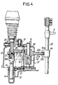
- Fig.4 is a sectional view taken along a line 4-4 in Fig.3;
- Fig.5 is a sectional view taken along a line 5-5 in Fig.2;
- Fig.6 is a diagram illustrating a shift pattern for a change lever;
- Fig.7 is a sectional view taken along a line 7-7 in Fig.3;
- Fig.8 is a view for explaining the operation;
- Figs.9 and 10 illustrate a second embodiment of the present invention, wherein
- Fig.9 is a view of the second embodiment similar to Fig.7;
- Fig.10 is a view for explaining the operation of the second embodiment; and
- Fig.11 is a view similar to Fig.7, but illustrating a third embodiment of the present invention.
- Referring to Fig.1, in a first embodiment of the invention, a transmission M for a vehicle includes six forward shift stages and one reverse shift stage. The transmission M comprises an input shaft Ms connected, in series, to an engine E through a clutch C, and an output shaft Cs, a reverse idle shaft Rs and a final shaft Fs disposed in parallel to the input shaft Ms.
- A main first-
shift gear 1 is fixedly mounted on the input shaft Ms and meshed with a counter first-shift gear 2 which is relatively rotatably carried on the output shaft Cs. Thus, a first shift stage is established by coupling the counter first-shift gear 2 to the output shaft Cs by means of asleeve 4 of a first-second shift synchronization mechanism driven by a first-second shift fork 3. A main first-shift gear 5 is fixedly mounted on the input shaft Ms and meshed with a counter second-shift gear 6 which is relatively rotatably carried on the output shaft Cs. Thus, a second shift stage is established by coupling the counter second-shift gear 6 to the output shaft Cs by means of thesleeve 4. - A main third-
shift gear 7 is relatively rotatably carried on the input shaft Ms and meshed with a counter third-shift gear 8 which is fixedly mounted on the output shaft Cs. Thus, a third shift stage is established by coupling the main third-shift gear 7 to the input shaft Ms by means of a sleeve 10 of a third-fourth shift synchronization mechanism which is driven by a third-fourth shift fork 9. A main fourth-shift gear 11 is relatively rotatably carried on the input shaft Ms and meshed with a counter fourth-shift gear 12 which is fixedly mounted on the output shaft Cs. Thus, a fourth shift stage is established by coupling the main fourth-shift gear 11 to the input shaft Ms by the sleeve 10. Likewise, a main fifth-shift gear 13 and a main sixth-shift gear 14 are relatively rotatably carried on the input shaft Ms. The main fifth-shift gear 13 and the sixth-shift gear 14 are meshed with a counter fifth-shift gear 15 and a counter sixth-shift gear 16 both fixedly mounted on the output shaft Cs, respectively. Thus, a fifth shift and a sixth shift are established by selectively coupling the main fifth-shift gear 13 and the main sixth-shift gear 14 to the input shaft Ms by means of a sleeve 18 of a third-fourth synchronization mechanism which is driven by a fifth-sixth shift fork 17. - A first 19 and a second reverse idle gear 20 are relatively rotatably carried on the reverse idle shaft Rs. The first
reverse idle gear 19 is meshed with a reverse drive gear 21 which is fixedly mounted on the input shaft Ms. And the second reverse idle gear 20 is meshed with a reverse drivengear 22 which is fixedly mounted on the output shaft Cs. Thus, a reverse-shift stage is established by sliding a sleeve 24 of a reverse synchronization mechanism by means of areverse shift fork 23 to integrally couple the first and secondreverse idle gears 19 and 20 with each other. - The rotation of the input shaft Ms is transmitted to the output shaft Cs by any of the first to sixth shift stages and the reverse shift stage, and further, the rotation of the output shaft Cs is transmitted through the
final drive gear 25 and the final drivengear 26 to the final shaft Fs. - As is apparent from Fig.2, the input shaft Ms, the output shaft Cs and the final shaft Fs are disposed sequentially from a left and upper position to a right and lower position within a
transmission case 27, and the reverse idle shaft Rs is disposed at a position rightward of and above the input shaft Ms. - Four shift rods, i.e., a first-
second shift rod 28 supporting the first-second shift fork 3, a third-fourth shift rod 29 supporting the third-fourth shift fork 9, a fifth-sixth shift rod 30 supporting the fifth-sixth shift fork 17 and a firstreverse shift rod 31 are disposed in parallel to one another at positions leftward of the input shaft Ms and the output shaft Cs. A shift change mechanism S is provided leftward of the fourrods - The structure of the shift change mechanism S will be described below with reference to Figs.2 to 6.
- As shown in Figs.3 and 4, a
change rod 34 connected to a change lever (not shown) is axially slidably and rotatably supported between apartition wall 32 of thetransmission case 27 and ashift box 33 fixed to thepartition wall 32. A neutral position of thechange rod 34 and two shift positions thereof on the opposite side of the neutral position are restrained by adetent mechanism 35. In a change lever operation pattern shown in Fig.6, N designates a neutral position; ① designates a first-shift position; ② designates a second-shift position; ③ designates a third-shift position; ④ designates a fourth-shift position; ⑤ desigantes a fifth-shift position; ⑥ designates a sixth-shift position; and R designates a reverse position. If the change lever is selectingly operated in a direction of an arrow A, thechange rod 34 is rotated, and if the change lever is selectingly operated in a direction of an arrow B, thechange rod 34 slides axially. - A
swingable member 37, Fig.3, is pivotally mounted to apivot 36 which is fixedly mounted in theshift box 33, Fig.4, in parallel to thechange rod 34. Anoperating arm 38 is secured to thechange rod 34. Apin 40 is fixedly mounted to theswingable member 37 to engage two rollers 39, Fig.3, mounted at a tip end of theoperating arm 38. Thus, when thechange rod 34 is rotated, theswingable member 37, with thepin 40 urged by the rollers 39 on theoperating arm 38, is swung about thepivot 36. Theswingable member 37 is stopped selectively at any of four select positions restrained by adetent mechanism 41, Fig.4. - A
shift arm 42 is axially slidably and rotatably carried on thepivot 36. Anelongaged hole 37a is provided in theswingable member 37 to extend axially of thepivot 36, and adrive projection 42a of theshift arm 42 extends through theelongated hole 37a to the outside. Thus, when theswingable member 37 is swung, theshift arm 42, having thedrive projection 42a urged through theelongated hole 37a, is swung about thepivot 36 along with theswingable member 37. Engage grooves 43a to 46a, Fig.3, are formed inshift pieces 43 to 46 secured to the fourshift rods 28 to 31 and are disposed on a locus of swinging movement of a tip end of thedrive projection 42a of theshift arm 42. In this case, the stop position of theswingable member 37 and, thus, the stop position of theshift arm 42, is restrained to a position in which thedrive projection 42a of theshift arm 42 engages the engagegroove 44a in the third-fourth shift piece 44, by biasing thepin 40 by a resilient force of aspring 47, Fig.4. - A circumferentially extending
elongated groove 38a is provided in a boss portion of theoperating arm 38 secured to thechange rod 34, Fig.4. A circumferentially extending elongated groove 42b is provided in a boss portion of theshift arm 42. Twopins lever 50 which is pivotally supported at its intermediate portion by thepivot 49 on abracket 48 rising on theshift box 33. The twopins elongated grooves 38a and 42b, respectively. Thus, when thechange rod 34 is moved axially by the shifting operation of the change lever, thelever 50, with one of thepins 51 urged into theelongated groove 38a, is swung about thepivot 49. As a result, theshift arm 42 with the elongated groove 42b urged on theother pin 52, slides in a direction reverse from the direction of sliding movement of thechange rod 34, while being guided on thepivot 36 and in theelongated hole 37a in theswingable member 37. - When the change lever is selectingly operated in the direction of the arrow A in Fig.6. the
shift arm 42 is rotated about thepivot 36 in Fig.3, so that thedrive projection 42a of theshift arm 42 is selectively engaged in any one of the engage grooves 43a to 46a formed in the fourshift pieces 43 to 46. When the change lever is shifted in the direction of the arrow B in Fig.6, theshift arm 42 slides along thepivot 36 in Fig.4, so that any shift piece engaging thedrive projection 42a of theshift arm 42 is driven axially, thereby establishing a predetermined shift stage. - The
swingable member 37, Fig.3, is provided with a pair of arcuately curved restrainingclaws drive projection 42a of theshift arm 42 is disposed between opposed tip ends of the restrainingclaws fourth shift piece 44 is driven, the restrainingclaws grooves second shift piece 43, the fifth-sixth shift piece 45 and thereverse shift piece 46, but not the third-fourth shift piece 44, thereby preventing the inadvertent or accidental operation of the threeshift pieces - As apparent from reference to Figs.2 and 5, the
reverse shift piece 46, fixed to the firstreverse shift rod 31, is prevented from being rotated by bringing itsdetent portion 46b into engagement with the adjacent fifth-sixth shift rod 30 for sliding movement. A secondreverse shift rod 53 having areverse shift fork 23 is supported on an upper portion of thetransmission case 27. Fig.2. in parallel to the firstreverse shift rod 31. Alever 56, Figs.2 and 5, is pivotally supported at its intermediate portion on abracket 54 which is mounted on thepartition wall 32 through the pivot 55. Opposite ends of thelever 56 are engaged in the engagegroove 46c formed in thereverse shift piece 46 and the engagegroove 23a formed in thereverse shift fork 23, respectively. - As apparent from Figs.3, 7 and 8, a restraining
member 58 comprising a substantially U-shaped curved plate, with an extension at a tip end, is pivotally mounted at its base end on abracket 57 on theshift box 33 through thepivot 59. Theshift box 33 is provided with a cup-shapedcylinder 60 opened at one end. A piston 61 is slidably received in thecylinder 60. A tip end of the restrainingmember 58 is opposed to that end face of the piston 61 which is exposed from an opening of thecylinder 60. The tip end of the restrainingmember 58 is biased in a direction of abutment against the piston 61 by means of aspring 62 mounted between the restrainingmember 58 and thebracket 57. Thus, if the speed of forward travelling of the vehicle is a predetermined value (e.g., several km/hr.) or more, a hydraulic pressure is applied, from an oil pump 64 (see Fig.2) connected to the output shaft Cs, through anoil passage 63 into thecylinder 60. When this hydraulic pressure overcomes a resilient force of thespring 62, the piston 61 is advanced, causing the restrainingmember 58 to be swung from an inoperative position shown in Fig.7 to an operative position shown in Fig.8. If the speed of forward travelling of the vehicle is less than the predetermined value, the piston 61 is retreated by the resilient force of thespring 62, thereby permitting the restrainingmember 58 to be returned from the operative position shown in Fig.8 to the inoperative position shown in Fig.7. - The
shift arm 42 includes a restrainingprojection 42c protruding to an opposite side from thedrive projection 42a, as can be seen from Fig.3. The restrainingprojection 42c protrudes in a plane of swinging movement of the restrainingmember 58 and is adapted to move along a select line L, which connects the following positions: a ①- ② select position, a ③- ④ select position, a ⑤- ⑥ select position and a reverse select position in operative association with the selecting operation of the change lever. Further, the restrainingprojection 42c is adapted to move perpendicularly to the select line L₁ toward the ① to ⑥ shift positions and the reverse shift position in operative association with the shifting operation of the change lever. The select line L₁ is established on a straight line passing throughpivot 59 of restrainingmember 58. - The restraining
member 58 is provided, at in inner side of the tip end of the U-shaped plate, with an engageportion 58a which is adapted to engage the restrainingprojection 42c to prevent theshift arm 42 from moving from the ⑤- ⑥ select position to the reverse select position, when the restrainingmember 58 is in the operative position. A face of abutment between the restrainingprojection 42c and the engageportion 58a is formed at a right angle with respect to the select line L₁, and the direction of a load F, received by the engageportion 58a from the restrainingprojection 42c, coincides with the select line L₁. The restrainingmember 58 is also formed with acam portion 58b which is adapted to be engaged by the restrainingmember 42c, when theshift arm 42 has been shifted to the ① shift position. - The operation of the embodiment of the present invention having the above-described construction will be described below.
- If the change lever is selectingly operated in the direction of A from the neutral position (the ③- ④ select position) shown in Fig.6, and is, e.g., moved to the ①- ② select position, the
change rod 34, Fig. 4, operatively associated with the change lever, is rotated and theswingable member 37, with thepin 40 urged by theoperating arm 38, is swung about thepivot 36. Thus, theshift arm 42 engaging theelongated hole 37a, in theswingable member 37, is swung about thepivot 36 in unison with theswingable member 37. As a result, thedrive projection 42a of theshift arm 42. Fig.3, is engaged into the engage groove 43a in the first-second shift piece 43 mounted on the first-second shift rod 28. - If the change lever is shiftingly operated from this condition toward the direction of B in Fig.6, for example, into the ① shift position or the ② shift position, the
change rod 34 slides axially in Fig.4. The sliding movement of thechange rod 34 is transmitted, through thelever 50, to theshift arm 42 to slide theshift arm 42 along thepivot 36. As a result, the first-second shift piece 43, engaging thedrive projection 42a of theshift arm 28, slides in a direction perpendicular to the sheet of Fig.3, along with the first-second shift rod 28, causing the first or second shift stage to be established by the first-second shift fork 3 mounted on the first-second shift rod 28. - Likewise, if the change lever is shifted into the ③ or ④ shift position, after selecting operation thereof to the ③- ④ select position, the third or fourth shift stage is established. If the change lever is shifted into the ⑤ or ⑥ shift position, after selecting operation thereof to the ⑤- ⑥ select position, the fifth or sixth shift stage is established.
- If the change lever is selectingly operated into the reverse select position, the
drive projection 42a of theshift arm 42 is brought into engagement with thereverse shift piece 46 in Fig.3. If the change lever is shifted from this condition into the reverse shift position, thereverse shift piece 46 slides in the leftward direction, as viewed in Fig.5, along with the firstreverse shift rod 31. As a result, the secondreverse shift rod 53 connected through thelever 56 to the firstreverse shift rod 31, slides in a rightward direction along with thereverse shift fork 23, thereby establishing the reverse shift stage. - If the
shift arm 42 is moved in operative association with the selecting and shifting operations of the change lever, the restrainingprojection 42c, provided on theshift arm 42 is moved according to the pattern shown in Fig.6. When the speed of forward travelling of the vehicle is less than the predetermined value, the oil pressure acting on thecylinder 60 is low, and the restrainingmember 58 is maintained at the inoperative position, shown in Fig.7, by the resilient force of thespring 62. Therefore, the restrainingprojection 42c can be freely moved to any of the ① to ⑥ shift positions and the reverse shift position without interference with the restrainingmember 58. - If the forward speed of the vehicle reaches and exceeds the predetermined value, so that the oil pressure is sufficient to overcome the resilient force of the
spring 62 applied to thecylinder 60, the piston 61 is advanced, causing the restrainingmember 58 to swing to the operative position shown in Fig.8. When the change lever is selectingly operated toward the reverse select position at this time, the restrainingprojection 42c is moved in the leftward direction as viewed in Fig.8 along the select line L₁. But in the course of this movement, the restrainingprojection 42c abuts against the engageportion 58a provided on the restrainingmember 58. Hence, the change lever cannot reach the reverse select position from the ⑤- ⑥ select position in Fig.6. This avoids inadvertently or accidentally established of the reverse shift stage during forward travelling of the vehicle. - When the restraining
projection 42c has abutted against the engageportion 58a of the restrainingmember 58, in the course of the movement thereof along the select line L₁, the select line L₁ lies on the straight line passing through thepivot 59, and the restrainingprojection 42c and the engageportion 58a abut against each other in a plane perpendicular to the select line L₁. For this reason, the direction of a load F, received by the engageportion 58a of the restrainingmember 58 from the restrainingprojection 42c, is in a direction of the select line L₁, i.e., is on the line passing through thepivot 59 of the restrainingmember 58, and such load F cannot produce a rotation moment on the restrainingmember 58. Therefore, the load F applies no load to thecylinder 60 and the piston 61, and cannot exert any influence to the durability of thecylinder 60 and the piston 61. - If the piston 61 is stuck at the position shown in Fig.8, for any reason, notwithstanding that the travel speed of the vehicle has become less than the predetermined value, the restraining
member 58 is retained at the operative position, thereby making it impossible to establish the reverse shift stage. In this case, if the change lever is shiftingly operated to the ① shift position, after selecting operation thereof to the ①- ② select position shown in Fig.6, the restrainingprojection 42c is moved from the ①- ② select position shown in Fig.8 to the ① shift position and, in the course of this movement, theprojection 42c abuts against thecam portion 58b of the restrainingmember 58. As a result, the restrainingmember 58 is forcedly swung from the operative position shown in Fig.8 toward the inoperative position shown in Fig.7, thereby making it possible again to establish the reverse shift stage. - Since the restraining
member 58 is formed in a U-shape surrounding the ①, ③ and ⑤ shift positions, this contributes to reducing space for location of the restrainingmember 58. Further, thecylinder 60 of the drive means is disposed in a space between the extension and an outer side of the U-shaped restraining member, thereby leading to a further compact arrangement. - Figs.9 and 10 illustrate a second embodiment of the present invention.
- A feature of this embodiment is the shape of a
cam portion 58c of a restrainingmember 58 which is different from the shape of thecam portion 58b in the previously-described first embodiment. Other portions of the cconstruction are the same as those of the first embodiment. - With the second embodiment, if the restraining
member 58 is stuck at an operative position, shown in Fig.10, thecam portion 58c can be urged by the restrainingprojection 42c only by moving the restrainingprojection 42c toward a ①- ② select position along a select line L₂, whereby the restrainingmember 58 can be returned to an inoperative position shown in Fig.9. - Fig.11 illustrates a third embodiment of the present invention.
- This embodiment is applied to a manual transmission in which forward shift stages and a reverse shift stage are provided in correspondence to the same select position, such as a manual transmission having five forward shift stages and a reverse shift stage. In this embodiment, if a hydraulic pressure is applied to the
cylinder 60 to swing the restrainingmember 58 by the piston 61 to an operative position shown by a solid line in Fig.11, the restrainingprojection 42c can be prevented by the engageportion 58a of the restrainingmember 58 from being moved on a shift line L₃ to a reverse shift position, thereby inhibiting the establishment of the reverse shift stage. At this time, the shift line L₃ lies on a straight line passing through thepivot 59, and the restrainingprojection 42c and the engageportion 58a abut against each other in a plane perpendicular to the shift line L₃. Hence, the direction of a load F received by the engageportion 58a from the restrainingprojection 42c lies on the straight line passing through thepivot 59. This ensures that a rotation moment can be prevented from being generated on the restrainingmember 58 by the load F, and the load of thecylinder 60 and the piston 61 can be reduced. - If the restraining
member 58 is stuck at the operative position, the restrainingmember 58 can be returned to an inoperative position, shown by a dashed line in Fig.11, by operating the restrainingprojection 42c directly to a ⑤ shift position along the shift line L₃ by means of the change lever to urge acam portion 58d of the restrainingmember 58 by the restrainingprojection 42c. - Although the embodiments of the present invention have been described in detail, it will be understood that the present invention is not limited to the above-described embodiments, and various minor modifications can be made without departing from the scope of the present invention defined in accompanying drawings.
- For example, in the above-described embodiments, when the restraining
projection 42c of theshift arm 42 is brought into abutment against the engageportion 58a of the restrainingmember 58, the restrainingprojection 42c is moved on the straight line passing through thepivot 59 of the restraining member 58 (namely, on the select lines L₁ and L₂ in the first and second embodiments, and on the shift line L₃ in the third embodiment), but the restrainingprojection 42c is not necessarily required to move on the straight line passing through thepivot 59. In this case, however, it is necessary to bring the direction of a load F received by the engageportion 58a from the restrainingprojection 42c into coincidence with the straight line passing through thepivot 59 by a means for properly changing the angle of the face of abutment between the restrainingprojection 42c of theshift member 42 and the engageportion 58a of the restrainingmember 58 or by another means. - In addition, in place of the drive means for the restraining
member 58 being comprised of a hydraulically operatedcylinder 60 and piston 61, it is possible to empoly other means such as a solenoid.
Claims (8)
- A manual transmission for a vehicle, in which any one of a plurality of forward shift stages and a reverse shift stage can selectively be established by movement of a shift member (42) operatively associated with the selecting and shifting operations of a change lever, and said shift member (42) is restrained from moving to a position in which the reverse shift stage is established, by the abutment of the shift member (42) against an engage portion (58a) provided on a restraining member (58) which is connected to a drive means (60, 61) for movement from an inoperative position to an operative position during forward travelling of the vehicle, wherein said restraining member (58) is provided with an abutment portion (58b, 58c, 58d) against which said shift member (42) is abutable, and said abutment portion (58b, 58c, 58d) is urged by a movement of said shift member (42) operatively associated with the operation of said change lever, thereby forcedly returning said restraining member (58) from the operative position to the inoperative position.
- A manual transmission for a vehicle according to claim 1, wherein said restraining member (58) is pivotally supported to a fixing portion (57) through a pivot (59), and a line of action of a load (F) received by the engage portion (58a) of said restraining member (58) from the said shift member (42) passes through said pivot (59).
- A manual transmission for a vehicle according to claim 1 or 2, wherein said restraining member (58) is forcedly returned from the operative position to the inoperative position by movement of said shift member (42) operatively associated with the shifting operation of said change lever to a predetermined forward shift stage.
- A manual transmission for a vehicle according to claim 1 or 2, wherein said restraining member (58) is forcedly returned from the operative position to the inoperative position by movement of said shift member (42) operatively associated with the shifting operation of said change lever to a predetermined forward shift stage,
- A manual transmission for a vehicle according to claim 3 or 4, wherein said restraining member (58) is bent into a U-shape surrounding a group of loci of movement of the shift member (42) in accordance with the shifting operation, said loci being located on a side of a locus of movement of the shift member (42) in accordance with the selecting operation, said restraining member (58) being pivotally supported at one end on said pivot (59) and being provided at an inner side of the other end with said engage portion (58a).
- A manual tansmission for a vehicle according to calim 5, wherein an extension is provided on said other end so as to extend in an opposite direction from the pivot (59) with respect to the engage portion (58a), a tip end of the extension being connected to said drive means (60, 61), said drive means (60, 61) being disposed in a space defined between the extension and an outer side of said U-shape restraining member (58).
- A manual transmission for a vehicle according to claim 1 or 2, wherein said change lever has a shift position for a predetermined forward shift stage and a shift position for the reverse shift stage on the same shift operation line, and said restraining member (58) is forcedly returned from the operative position to the inoperative position by movement of said shift member (42) operatively associated with the shifting operation of said change lever to said predetermined forward shift stage.
- A manual transmission for a vehicle substantially as described herein with reference to the accompanying drawings.
Applications Claiming Priority (2)
| Application Number | Priority Date | Filing Date | Title |
|---|---|---|---|
| JP1991090714U JP2588978Y2 (en) | 1991-11-06 | 1991-11-06 | Manual transmission for vehicles |
| JP90714/91U | 1991-11-06 |
Publications (2)
| Publication Number | Publication Date |
|---|---|
| EP0541098A1 true EP0541098A1 (en) | 1993-05-12 |
| EP0541098B1 EP0541098B1 (en) | 1997-08-06 |
Family
ID=14006209
Family Applications (1)
| Application Number | Title | Priority Date | Filing Date |
|---|---|---|---|
| EP92118989A Expired - Lifetime EP0541098B1 (en) | 1991-11-06 | 1992-11-05 | Manual transmission for vehicle |
Country Status (4)
| Country | Link |
|---|---|
| US (1) | US5331863A (en) |
| EP (1) | EP0541098B1 (en) |
| JP (1) | JP2588978Y2 (en) |
| DE (1) | DE69221426T2 (en) |
Cited By (5)
| Publication number | Priority date | Publication date | Assignee | Title |
|---|---|---|---|---|
| EP0601741B1 (en) * | 1992-12-11 | 1997-03-19 | Eaton Corporation | Downshift inhibitor |
| FR2776043A1 (en) * | 1998-03-16 | 1999-09-17 | Renault | GEAR CHANGE DEVICE FOR GEARBOX |
| EP1031772A1 (en) * | 1999-02-22 | 2000-08-30 | Honda Giken Kogyo Kabushiki Kaisha | Gearshift with rocking levers |
| EP1273832A1 (en) * | 2001-07-04 | 2003-01-08 | GETRAG FORD Transmissions GmbH | Shift device for motor vehicle and method of guiding a shift lever |
| EP1965099A3 (en) * | 2007-03-01 | 2010-10-20 | Dr. Ing. h.c. F. Porsche AG | Selector device with spring-biasing arrangement for providing selection feel in a multi-ratio gearbox |
Families Citing this family (6)
| Publication number | Priority date | Publication date | Assignee | Title |
|---|---|---|---|---|
| JP2581917Y2 (en) * | 1992-11-27 | 1998-09-24 | 三菱自動車工業株式会社 | Transmission operating device |
| DE4443523C1 (en) * | 1994-12-07 | 1996-05-02 | Daimler Benz Ag | Switching device for a gear change transmission of a motor vehicle |
| JPH09112691A (en) * | 1995-10-16 | 1997-05-02 | Nissan Motor Co Ltd | Remote control device for manual transmission |
| DE19539599C2 (en) * | 1995-10-25 | 1997-08-14 | Ford Werke Ag | Switching device for motor vehicle change gearbox with braking of the input shaft when switching on the reverse gear |
| DE102009027533A1 (en) * | 2009-07-08 | 2011-01-20 | Zf Friedrichshafen Ag | Switching device of a motor vehicle gearbox |
| JP2012189156A (en) * | 2011-03-11 | 2012-10-04 | Aisin Ai Co Ltd | Manual transmission |
Citations (5)
| Publication number | Priority date | Publication date | Assignee | Title |
|---|---|---|---|---|
| US3866488A (en) * | 1972-01-24 | 1975-02-18 | Toyota Motor Co Ltd | Manually operated shift assembly with restraining action for shifting to reverse |
| US4133219A (en) * | 1977-04-27 | 1979-01-09 | Borg-Warner Corporation | Transmission shift control mechanism |
| GB2183753A (en) * | 1985-12-04 | 1987-06-10 | Ford Motor Co | Gear-shifting mechanism for preventing accidental engagement of reverse |
| US5036722A (en) * | 1988-11-02 | 1991-08-06 | Hyundai Motor Company | Backward shift control device of a manual transmission gear for use in automobiles |
| US5078020A (en) * | 1987-08-06 | 1992-01-07 | Nissan Motor Company, Ltd. | Reverse select system for manual transmission |
Family Cites Families (9)
| Publication number | Priority date | Publication date | Assignee | Title |
|---|---|---|---|---|
| JPS522063B2 (en) * | 1973-11-19 | 1977-01-19 | ||
| JPS546238A (en) * | 1977-06-15 | 1979-01-18 | Toyota Motor Corp | Speed shifting mechanism for automotive transmission |
| US4228693A (en) * | 1978-12-11 | 1980-10-21 | Borg-Warner Corporation | Transmission shift control apparatus |
| JPS5790446A (en) * | 1980-11-21 | 1982-06-05 | Aisan Ind Co Ltd | Manual transmission for automobile |
| JPH0665909B2 (en) * | 1984-07-09 | 1994-08-24 | 富士重工業株式会社 | Gear shift operation mechanism for vehicle gearbox |
| JPH0547897Y2 (en) * | 1987-04-09 | 1993-12-17 | ||
| JPS6425555A (en) * | 1987-07-22 | 1989-01-27 | Matsushita Electronics Corp | Trench forming method |
| JPH01101233A (en) * | 1987-10-12 | 1989-04-19 | Japan Electron Control Syst Co Ltd | manual transmission shift device |
| JPH0265753A (en) * | 1988-08-30 | 1990-03-06 | Keiichiro Murofushi | Drawing device for highly hydrated men (noodle) and drawing method of same men |
-
1991
- 1991-11-06 JP JP1991090714U patent/JP2588978Y2/en not_active Expired - Lifetime
-
1992
- 1992-11-03 US US07/970,995 patent/US5331863A/en not_active Expired - Lifetime
- 1992-11-05 DE DE69221426T patent/DE69221426T2/en not_active Expired - Lifetime
- 1992-11-05 EP EP92118989A patent/EP0541098B1/en not_active Expired - Lifetime
Patent Citations (5)
| Publication number | Priority date | Publication date | Assignee | Title |
|---|---|---|---|---|
| US3866488A (en) * | 1972-01-24 | 1975-02-18 | Toyota Motor Co Ltd | Manually operated shift assembly with restraining action for shifting to reverse |
| US4133219A (en) * | 1977-04-27 | 1979-01-09 | Borg-Warner Corporation | Transmission shift control mechanism |
| GB2183753A (en) * | 1985-12-04 | 1987-06-10 | Ford Motor Co | Gear-shifting mechanism for preventing accidental engagement of reverse |
| US5078020A (en) * | 1987-08-06 | 1992-01-07 | Nissan Motor Company, Ltd. | Reverse select system for manual transmission |
| US5036722A (en) * | 1988-11-02 | 1991-08-06 | Hyundai Motor Company | Backward shift control device of a manual transmission gear for use in automobiles |
Non-Patent Citations (1)
| Title |
|---|
| PATENT ABSTRACTS OF JAPAN vol. 013, no. 311 (M-851)17 July 1989 & JP-A-11 01 233 ( JAPAN ELECTRON CONTROL SYST CO LTD ) * |
Cited By (6)
| Publication number | Priority date | Publication date | Assignee | Title |
|---|---|---|---|---|
| EP0601741B1 (en) * | 1992-12-11 | 1997-03-19 | Eaton Corporation | Downshift inhibitor |
| FR2776043A1 (en) * | 1998-03-16 | 1999-09-17 | Renault | GEAR CHANGE DEVICE FOR GEARBOX |
| EP1031772A1 (en) * | 1999-02-22 | 2000-08-30 | Honda Giken Kogyo Kabushiki Kaisha | Gearshift with rocking levers |
| US6374690B1 (en) | 1999-02-22 | 2002-04-23 | Honda Giken Kogyo Kabushiki Kaisha | Gearshift |
| EP1273832A1 (en) * | 2001-07-04 | 2003-01-08 | GETRAG FORD Transmissions GmbH | Shift device for motor vehicle and method of guiding a shift lever |
| EP1965099A3 (en) * | 2007-03-01 | 2010-10-20 | Dr. Ing. h.c. F. Porsche AG | Selector device with spring-biasing arrangement for providing selection feel in a multi-ratio gearbox |
Also Published As
| Publication number | Publication date |
|---|---|
| JP2588978Y2 (en) | 1999-01-20 |
| DE69221426D1 (en) | 1997-09-11 |
| EP0541098B1 (en) | 1997-08-06 |
| US5331863A (en) | 1994-07-26 |
| JPH0542822U (en) | 1993-06-11 |
| DE69221426T2 (en) | 1997-12-11 |
Similar Documents
| Publication | Publication Date | Title |
|---|---|---|
| US7752936B2 (en) | Automatic transmission assembly for a vehicle, and vehicle incorporating same | |
| US5950782A (en) | Arrangement and method for locking a selector mechanism of an automatically operating change-speed gearbox | |
| EP0541098A1 (en) | Manual transmission for vehicle | |
| US5724856A (en) | Shifter for manual transmissions | |
| US4307624A (en) | Transmission gear selector arm and sleeves for shifting forks | |
| US6892600B2 (en) | Changing system in manual transmission | |
| EP1271014B1 (en) | Gear shifting system in manual transmission | |
| KR950011190A (en) | Automatic shifting mechanism | |
| US4666023A (en) | Transmission shifting arrangement | |
| KR100250373B1 (en) | Shift device for a change speed gearbox | |
| US4827792A (en) | Transmission shift control mechanism | |
| US5284065A (en) | Removable overdrive lockout | |
| CA1191797A (en) | Means for increasing the safety of parking brake mechanism of automatic transmissions | |
| US4531424A (en) | Gear shift mechanism for transmission | |
| US5806368A (en) | Gearshift device for a semiautomatically shiftable change-speed gearbox | |
| KR0134363B1 (en) | Transmission operation device of automobile transmission | |
| KR200154500Y1 (en) | Selector of automatic transmission | |
| CA1140026A (en) | Shift control for transmission | |
| JP3511671B2 (en) | Reverse gear noise prevention device for transmission | |
| KR0171729B1 (en) | Reverse transmission of manual transmission for automobiles | |
| KR950011270B1 (en) | Speed change device | |
| KR0177961B1 (en) | Reverse prevention device of manual transmission for vehicle | |
| KR200167723Y1 (en) | Reverse misoperation prevention device of manual transmission | |
| KR950000788Y1 (en) | Reverse malfunction prevention device of car | |
| KR100191595B1 (en) | Integral shift fork of manual transmission |
Legal Events
| Date | Code | Title | Description |
|---|---|---|---|
| PUAI | Public reference made under article 153(3) epc to a published international application that has entered the european phase |
Free format text: ORIGINAL CODE: 0009012 |
|
| AK | Designated contracting states |
Kind code of ref document: A1 Designated state(s): DE FR GB |
|
| 17P | Request for examination filed |
Effective date: 19930809 |
|
| 17Q | First examination report despatched |
Effective date: 19930915 |
|
| GRAG | Despatch of communication of intention to grant |
Free format text: ORIGINAL CODE: EPIDOS AGRA |
|
| GRAH | Despatch of communication of intention to grant a patent |
Free format text: ORIGINAL CODE: EPIDOS IGRA |
|
| GRAH | Despatch of communication of intention to grant a patent |
Free format text: ORIGINAL CODE: EPIDOS IGRA |
|
| GRAA | (expected) grant |
Free format text: ORIGINAL CODE: 0009210 |
|
| AK | Designated contracting states |
Kind code of ref document: B1 Designated state(s): DE FR GB |
|
| REF | Corresponds to: |
Ref document number: 69221426 Country of ref document: DE Date of ref document: 19970911 |
|
| ET | Fr: translation filed | ||
| PLBE | No opposition filed within time limit |
Free format text: ORIGINAL CODE: 0009261 |
|
| STAA | Information on the status of an ep patent application or granted ep patent |
Free format text: STATUS: NO OPPOSITION FILED WITHIN TIME LIMIT |
|
| 26N | No opposition filed | ||
| REG | Reference to a national code |
Ref country code: GB Ref legal event code: IF02 |
|
| PGFP | Annual fee paid to national office [announced via postgrant information from national office to epo] |
Ref country code: GB Payment date: 20071031 Year of fee payment: 16 Ref country code: FR Payment date: 20071108 Year of fee payment: 16 |
|
| GBPC | Gb: european patent ceased through non-payment of renewal fee |
Effective date: 20081105 |
|
| REG | Reference to a national code |
Ref country code: FR Ref legal event code: ST Effective date: 20090731 |
|
| PG25 | Lapsed in a contracting state [announced via postgrant information from national office to epo] |
Ref country code: GB Free format text: LAPSE BECAUSE OF NON-PAYMENT OF DUE FEES Effective date: 20081105 |
|
| PGFP | Annual fee paid to national office [announced via postgrant information from national office to epo] |
Ref country code: DE Payment date: 20101104 Year of fee payment: 19 |
|
| PG25 | Lapsed in a contracting state [announced via postgrant information from national office to epo] |
Ref country code: FR Free format text: LAPSE BECAUSE OF NON-PAYMENT OF DUE FEES Effective date: 20081130 |
|
| REG | Reference to a national code |
Ref country code: DE Ref legal event code: R119 Ref document number: 69221426 Country of ref document: DE Effective date: 20120601 |
|
| PG25 | Lapsed in a contracting state [announced via postgrant information from national office to epo] |
Ref country code: DE Free format text: LAPSE BECAUSE OF NON-PAYMENT OF DUE FEES Effective date: 20120601 |