EP0545800A1 - Fremdpartikelfilter im Sekundärkreislauf eines Dampferzeugers - Google Patents
Fremdpartikelfilter im Sekundärkreislauf eines Dampferzeugers Download PDFInfo
- Publication number
- EP0545800A1 EP0545800A1 EP92403225A EP92403225A EP0545800A1 EP 0545800 A1 EP0545800 A1 EP 0545800A1 EP 92403225 A EP92403225 A EP 92403225A EP 92403225 A EP92403225 A EP 92403225A EP 0545800 A1 EP0545800 A1 EP 0545800A1
- Authority
- EP
- European Patent Office
- Prior art keywords
- grids
- steam generator
- bundle
- envelope
- external
- Prior art date
- Legal status (The legal status is an assumption and is not a legal conclusion. Google has not performed a legal analysis and makes no representation as to the accuracy of the status listed.)
- Granted
Links
- XLYOFNOQVPJJNP-UHFFFAOYSA-N water Substances O XLYOFNOQVPJJNP-UHFFFAOYSA-N 0.000 claims abstract description 32
- 238000009434 installation Methods 0.000 claims abstract description 5
- 238000004519 manufacturing process Methods 0.000 claims description 5
- 238000001914 filtration Methods 0.000 claims description 3
- 238000011144 upstream manufacturing Methods 0.000 claims description 2
- 238000012423 maintenance Methods 0.000 description 2
- 239000012530 fluid Substances 0.000 description 1
- 239000002184 metal Substances 0.000 description 1
- 238000000034 method Methods 0.000 description 1
- 239000000203 mixture Substances 0.000 description 1
- 229920006395 saturated elastomer Polymers 0.000 description 1
- 238000000926 separation method Methods 0.000 description 1
- 238000003466 welding Methods 0.000 description 1
Images


Classifications
-
- G—PHYSICS
- G21—NUCLEAR PHYSICS; NUCLEAR ENGINEERING
- G21D—NUCLEAR POWER PLANT
- G21D1/00—Details of nuclear power plant
- G21D1/02—Arrangements of auxiliary equipment
-
- F—MECHANICAL ENGINEERING; LIGHTING; HEATING; WEAPONS; BLASTING
- F22—STEAM GENERATION
- F22B—METHODS OF STEAM GENERATION; STEAM BOILERS
- F22B1/00—Methods of steam generation characterised by form of heating method
- F22B1/02—Methods of steam generation characterised by form of heating method by exploitation of the heat content of hot heat carriers
- F22B1/023—Methods of steam generation characterised by form of heating method by exploitation of the heat content of hot heat carriers with heating tubes for nuclear reactors, as long as they are not classified according to a specified heating fluid, in another group
- F22B1/025—Methods of steam generation characterised by form of heating method by exploitation of the heat content of hot heat carriers with heating tubes for nuclear reactors, as long as they are not classified according to a specified heating fluid, in another group with vertical U shaped tubes carried on a horizontal tube sheet
-
- Y—GENERAL TAGGING OF NEW TECHNOLOGICAL DEVELOPMENTS; GENERAL TAGGING OF CROSS-SECTIONAL TECHNOLOGIES SPANNING OVER SEVERAL SECTIONS OF THE IPC; TECHNICAL SUBJECTS COVERED BY FORMER USPC CROSS-REFERENCE ART COLLECTIONS [XRACs] AND DIGESTS
- Y02—TECHNOLOGIES OR APPLICATIONS FOR MITIGATION OR ADAPTATION AGAINST CLIMATE CHANGE
- Y02E—REDUCTION OF GREENHOUSE GAS [GHG] EMISSIONS, RELATED TO ENERGY GENERATION, TRANSMISSION OR DISTRIBUTION
- Y02E30/00—Energy generation of nuclear origin
Definitions
- the invention relates to steam generators used in nuclear installations for the production of electrical energy, in particular those using one or more pressurized water reactors.
- the invention relates in particular to a device placed in the secondary circuit of this steam generator.
- a primary circuit is used for the evacuation of the energy produced by the reactor. Pressurized water is trapped in this primary circuit.
- a heat exchanger such as a steam generator, is used to exploit the thermal energy extracted from the nuclear reactor by this primary circuit.
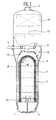
- Such a steam generator is shown in Figure 1.
- the inlet of the primary circuit is referenced 1 and the outlet thereof is referenced 2.
- These two orifices are located at the lower end of the steam generator.
- the pressurized water circulating in the primary circuit crosses inside the steam generator a bundle of tube 3, called a tubular bundle. The latter is placed at the bottom of the steam generator.
- the water inlet of the secondary circuit 4 is lateral and placed in the upper part.
- the output 5 of this secondary circuit is located in the upper part of the steam generator.
- the water from the secondary circuit is distributed by a supply ring 6 and is channeled between the pressure envelope 7 of the steam generator and the envelope 8 of the bundle 3. It then rises along the tube bundle 3, in contact with which it is vaporized. Arriving at the upper end 9 thereof, it is collected by the upper part 10 of the bundle casing 7 and by evacuation pipes 12 equipped with centrifugal separators responsible for separating water from steam.
- the steam is then evacuated through the outlet 5 after having passed through one or more dryers 13 completing the separation of the water from the steam.
- the saturated water thus separated from the vapor and called recirculated water, is channeled, via the pipe (s) 15, before being mixed with the water coming from the supply ring 6.
- Objects foreign to the steam generator of various sizes, shapes and natures and called migrant bodies may be accidentally introduced into the steam generator via the secondary water supply system, or during maintenance operations.
- these bodies can be set in motion and entrained by the secondary fluid to come to block in different places of the steam generator, such as the tube plate 31, or between the tubes of the tube bundle 3.
- These objects can in particular damage the walls of the tubes by impact or by friction.
- the object of the invention is to limit the size and the number of migrant bodies, coming from the secondary water supply system, and from the upper part of the steam generator capable of reaching the tube plate and damaging the tube bundle.
- the main object of the invention is a device for trapping migrant bodies inside the secondary circuit of a steam generator of a nuclear installation for the production of electrical energy, consisting of a set grids or equivalent mechanical filtering systems occupying for optimum efficiency the entire annular section of the secondary circuit, downstream of the water inlet pipes in the secondary circuit and upstream of the water inlet in the primary circuit tubular bundle.
- the device according to the invention is all the more effective as the grids have meshes of a maximum width less than this distance, so as not to leave pass objects or bodies likely to get caught between the tubes.
- the grids or the like consist of sectors of crowns mounted on two radial gussets common to two adjacent sectors and welded to the envelope of the bundle.
- the grids are preferably screwed onto the gussets to be removable.
- the width of the grids is very slightly less than the width of the annular section of the secondary circuit at the place where the grids are placed so as to leave a play of a few millimeters, so as to allow for expansion between the pressure jacket and the steam generator bundle jacket.
- first external slats can be placed on the internal wall of the pressure envelope of the steam generator in the annular section to fill the external circular clearance between the grids and the pressure envelope.
- second circular slats fixed at the outer periphery of the grids make it possible to avoid re-training in the space between the pressure envelope and the bundle envelope of the objects trapped on the grids.
- internal slats can be placed between the grids and the external wall of the bundle envelope.
- the grids are a few centimeters thick so as to have sufficient mechanical strength.
- FIG 2 shows the intermediate part of the steam generator of Figure 1.
- the pressure envelope 7 widens, that is to say it has a conical shape.
- a space 14, called the water return, therefore remains between the pressure envelope 7 and the outside of the bundle wrapped 8. It is in this space that the water distributed by the mixed supply ring to the recirculated water is channeled in the lower part of the steam generator. It is also at this location that one can choose to place the device according to the invention.
- These grids 16 are preferably positioned in this water return 14 by means of gussets 19, themselves preferably fixed on the external surface 17 of the upper part 10 of the bundle envelope 8.
- the meshes of the grids 16 are dimensioned so as not to let pass objects or migrating bodies liable to be trapped between two tubes of the beam tubular 3.
- the meshes of the grids 16 must not allow objects whose size exceeds the determined distance D separating the tubes to pass. To this end, provision is therefore made for the maximum width M of the meshes of the grids 16 to be less than this distance D.
- the grids 16 have been shown with a certain thickness E, or in other words, a certain height. Given that these grids 16 can be made of metal, they can thus have sufficient mechanical strength to withstand various stresses, in particular vertical stresses directed from top to bottom. In fact, the grids 16 must first of all resist the hydraulic forces imposed by the mixture of water from the feed ring and recirculated water descending between the pressure envelope 7 and the pressure envelope. beam 8 and this in normal and accidental operation. Furthermore, during assembly of the steam generator, these grids 16 can thus accommodate one or more operators, thus facilitating the installation of different elements of the steam generator as well as control and maintenance operations. The grids 16 in this case constitute a sort of walkway around the upper part 10 of the bundle envelope 8. On the other hand, the grids 16 must be able to withstand without damage (rupture or deformation) the impacts of migrant bodies .
- a first form of mesh for the grids 16 is the square shape. Without taking into account the scale at which these meshes are represented, it must therefore be pointed out that the diagonal of the square of each of the meshes must be less than the distance D separating the tubes from the tubular bundle. This is an order of magnitude to indicate that the mesh size of the grids of the device according to the invention must be such that they must not allow objects likely to get caught or braced between the tubes of this tube bundle.
- This grid with square meshes can be produced using a first series of sheets parallel to each other 23, to each delimit two opposite sides of the meshes of the same column or row.
- a second series of sheet 24 perpendicular to that 23 of the first series can be embedded in the latter to define the other two opposite sides of the corresponding meshes.
- the embedding can be obtained by making slots 29 over half the height in each of the sheets of each series at the point where the sheets 23 and 24 intersect.
- FIG. 4 represents grids with meshes of triangular shape. It is thus possible to build a thick grid composed of a series of corrugated or folded sheets welded on either side on two flat sheets. The largest side of the triangle must be less than the distance D separating the tubes from the tube bundle.
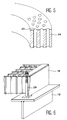
- FIG. 5 shows a third embodiment of grids constructed in a rigid plate 26 in which holes 27 have been drilled, for example in staggered rows.
- the diameter of the holes 27 must obviously be less than the distance D separating the tubes from the tube bundle.
- FIGS. 3, 4 and 5 are not limiting as regards the production and the shape of the meshes constituting the grids 16.
- FIG. 6 shows in detail a method of fixing the grids 16 to their gussets 19.
- the latter have been represented by a T-shaped profile.
- This type of gusset 19 extends radially relative to the envelope of bundles of the generator steam. They can be welded to the latter.
- the grids 16 can be attached to these gussets 19 by screwing using, for example, bolts 28, which makes it possible to dismantle these grids 16. They can also be welded to the gussets 19. It is thus possible to each gusset 19 fix two adjacent grids 16 with or without leaving a space between these two adjacent grids.
- the T-shape of the gussets and in particular the upper part of the T makes it possible to close off any radial clearances remaining between the grids 16.
- the grids 16 therefore make it possible to form a sort of grating for filtering or trapping migrant bodies coming from the upper internal circuits of the steam generator, from the food water system of the secondary circuit, or quite simply circulating in the steam generator. .
- the support mode can be different: welding on other parts or by other means (screwing for example).
- the altitude of the device in the steam generator can be chosen at any level between the secondary water supply ring and the tube plate.
- this grating grating facilitates the mounting of the steam generator and can be carried out in the factory during the manufacture of the latter.
- the device makes it possible to trap all of the migrant bodies liable to damage the internal parts of the steam generator above the tubular plate 31, this for the migrant bodies coming from both the feed ring and the upper part of the steam generator.
Landscapes
- Engineering & Computer Science (AREA)
- Physics & Mathematics (AREA)
- General Engineering & Computer Science (AREA)
- Life Sciences & Earth Sciences (AREA)
- Sustainable Development (AREA)
- Sustainable Energy (AREA)
- Thermal Sciences (AREA)
- Mechanical Engineering (AREA)
- Plasma & Fusion (AREA)
- High Energy & Nuclear Physics (AREA)
- Structure Of Emergency Protection For Nuclear Reactors (AREA)
- Monitoring And Testing Of Nuclear Reactors (AREA)
Applications Claiming Priority (2)
| Application Number | Priority Date | Filing Date | Title |
|---|---|---|---|
| FR9114900A FR2684433B1 (fr) | 1991-12-02 | 1991-12-02 | Dispositif de piegeage de corps migrants a l'interieur du circuit secondaire d'un generateur de vapeur. |
| FR9114900 | 1991-12-02 |
Publications (2)
| Publication Number | Publication Date |
|---|---|
| EP0545800A1 true EP0545800A1 (de) | 1993-06-09 |
| EP0545800B1 EP0545800B1 (de) | 1996-07-03 |
Family
ID=9419571
Family Applications (1)
| Application Number | Title | Priority Date | Filing Date |
|---|---|---|---|
| EP92403225A Expired - Lifetime EP0545800B1 (de) | 1991-12-02 | 1992-11-30 | Fremdpartikelfilter im Sekundärkreislauf eines Dampferzeugers |
Country Status (10)
| Country | Link |
|---|---|
| US (1) | US5390219A (de) |
| EP (1) | EP0545800B1 (de) |
| JP (1) | JP3131318B2 (de) |
| KR (1) | KR100358682B1 (de) |
| CN (1) | CN1028930C (de) |
| CA (1) | CA2083888C (de) |
| DE (1) | DE69211967D1 (de) |
| FR (1) | FR2684433B1 (de) |
| TW (1) | TW221512B (de) |
| ZA (1) | ZA929308B (de) |
Cited By (1)
| Publication number | Priority date | Publication date | Assignee | Title |
|---|---|---|---|---|
| EP1985917A3 (de) * | 2006-11-28 | 2009-03-11 | Westinghouse Electric Company LLC | Sammelwehr für lose Teile eines Dampferzeugers |
Families Citing this family (5)
| Publication number | Priority date | Publication date | Assignee | Title |
|---|---|---|---|---|
| US5539793A (en) * | 1994-10-27 | 1996-07-23 | General Electric Company | Lower tie plate debris catcher for a nuclear reactor |
| FR2778222B1 (fr) | 1998-05-04 | 2000-07-21 | Framatome Sa | Dispositif de filtration et d'arret de corps etrangers vehicules par l'eau d'alimentation d'un generateur de vapeur |
| FR2851031B1 (fr) * | 2003-02-12 | 2005-05-06 | Framatome Anp | Generateur de vapeur comportant un dispositif de fourniture d'eau d'alimentation realisant le piegeage de corps etrangers |
| JP4599319B2 (ja) * | 2006-02-28 | 2010-12-15 | 三菱重工業株式会社 | 気水分離器 |
| US8215379B2 (en) * | 2009-04-29 | 2012-07-10 | Babcock & Wilcox Canada Ltd. | Feedwater debris trap |
Citations (3)
| Publication number | Priority date | Publication date | Assignee | Title |
|---|---|---|---|---|
| GB1126306A (en) * | 1966-09-01 | 1968-09-05 | Westinghouse Electric Corp | Vapor generating apparatus |
| US3916844A (en) * | 1974-07-29 | 1975-11-04 | Combustion Eng | Steam generator blowdown apparatus |
| EP0183049A1 (de) * | 1984-11-15 | 1986-06-04 | Westinghouse Electric Corporation | Strömungsverteilerlochplatte |
Family Cites Families (4)
| Publication number | Priority date | Publication date | Assignee | Title |
|---|---|---|---|---|
| US4261300A (en) * | 1978-12-26 | 1981-04-14 | Combustion Engineering, Inc. | Nuclear steam generator |
| US4343707A (en) * | 1980-03-10 | 1982-08-10 | Electric Power Research Institute, Inc. | Method and apparatus for separating out solids suspended in flowing, pure water systems |
| FR2598800B1 (fr) * | 1986-05-14 | 1990-10-05 | Framatome Sa | Separateur de particules liquides a ailettes |
| US5019329A (en) * | 1989-12-26 | 1991-05-28 | Westinghouse Electric Corp. | System and method for vertically flushing a steam generator during a shock wave cleaning operation |
-
1991
- 1991-12-02 FR FR9114900A patent/FR2684433B1/fr not_active Expired - Lifetime
-
1992
- 1992-11-26 CA CA002083888A patent/CA2083888C/en not_active Expired - Lifetime
- 1992-11-26 TW TW081109484A patent/TW221512B/zh not_active IP Right Cessation
- 1992-11-30 EP EP92403225A patent/EP0545800B1/de not_active Expired - Lifetime
- 1992-11-30 DE DE69211967T patent/DE69211967D1/de not_active Expired - Lifetime
- 1992-12-01 CN CN92114397A patent/CN1028930C/zh not_active Expired - Lifetime
- 1992-12-01 ZA ZA929308A patent/ZA929308B/xx unknown
- 1992-12-01 KR KR1019920022977A patent/KR100358682B1/ko not_active Expired - Fee Related
- 1992-12-02 US US07/984,682 patent/US5390219A/en not_active Expired - Lifetime
- 1992-12-02 JP JP04323396A patent/JP3131318B2/ja not_active Expired - Fee Related
Patent Citations (3)
| Publication number | Priority date | Publication date | Assignee | Title |
|---|---|---|---|---|
| GB1126306A (en) * | 1966-09-01 | 1968-09-05 | Westinghouse Electric Corp | Vapor generating apparatus |
| US3916844A (en) * | 1974-07-29 | 1975-11-04 | Combustion Eng | Steam generator blowdown apparatus |
| EP0183049A1 (de) * | 1984-11-15 | 1986-06-04 | Westinghouse Electric Corporation | Strömungsverteilerlochplatte |
Cited By (1)
| Publication number | Priority date | Publication date | Assignee | Title |
|---|---|---|---|---|
| EP1985917A3 (de) * | 2006-11-28 | 2009-03-11 | Westinghouse Electric Company LLC | Sammelwehr für lose Teile eines Dampferzeugers |
Also Published As
| Publication number | Publication date |
|---|---|
| CA2083888C (en) | 2002-10-22 |
| CN1028930C (zh) | 1995-06-14 |
| CN1073031A (zh) | 1993-06-09 |
| EP0545800B1 (de) | 1996-07-03 |
| TW221512B (de) | 1994-03-01 |
| FR2684433A1 (fr) | 1993-06-04 |
| JPH05256989A (ja) | 1993-10-08 |
| US5390219A (en) | 1995-02-14 |
| KR930014627A (ko) | 1993-07-23 |
| ZA929308B (en) | 1993-05-24 |
| JP3131318B2 (ja) | 2001-01-31 |
| FR2684433B1 (fr) | 1994-01-07 |
| KR100358682B1 (ko) | 2003-01-24 |
| CA2083888A1 (en) | 1993-12-15 |
| DE69211967D1 (de) | 1996-08-08 |
Similar Documents
| Publication | Publication Date | Title |
|---|---|---|
| EP0545800B1 (de) | Fremdpartikelfilter im Sekundärkreislauf eines Dampferzeugers | |
| FR2664733A1 (fr) | Embout inferieur d'un assemblage combustible pour reacteur nucleaire comportant une plaque adaptatrice et une plaque de filtration accolee a la plaque adaptatrice. | |
| EP0238390B1 (de) | Innere Struktur eines Kernreaktors mit länglichem Druckbehälter | |
| FR2598800A1 (fr) | Separateur de particules liquides a ailettes | |
| FR2778224A1 (fr) | Generateur de vapeur comportant un dispositif d'alimentation en eau perfectionne | |
| FR2506063A1 (fr) | Reacteur nucleaire comportant un refroidissement des structures peripheriques par convection naturelle d'air | |
| FR2707733A1 (fr) | Générateur de vapeur à cyclones démontables. | |
| EP0626536A1 (de) | Dampferzeuger ausgerüstet mit einem Fremdpartikelfilter | |
| EP0607071B1 (de) | Wärmetauscher mit oben durch einen Überlauf gespeistes Sekundärfluid | |
| EP3861270B1 (de) | Plattenpaar für einen plattenwärmetauscher | |
| EP0189029B1 (de) | Mischkondensator, insbesondere zur Ausnützung der Seewärmeenergie | |
| FR2584227A1 (fr) | Dispositif de condensation de vapeur d'eau sous pression et son application au refroidissement d'un reacteur nucleaire apres un incident. | |
| FR2519462A1 (fr) | Dispositif d'evacuation de secours de la chaleur dissipee par un reacteur nucleaire a neutrons rapides a l'arret | |
| EP0568434B1 (de) | Vorrichtung zur Abgabe und Verteilung von Speise- und Rezirkulationswasser in der Sekundärseite eines Dampferzeugers | |
| FR3029677A1 (fr) | Grille de maintien d'assemblage combustible nucleaire | |
| EP0131508B1 (de) | Ein mit einem Hilfskühler versehener Wärmetauscher | |
| FR2851031A1 (fr) | Generateur de vapeur comportant un dispositif de fourniture d'eau d'alimentation realisant le piegeage de corps etrangers | |
| FR2532404A1 (fr) | Fond de chambre de combustion pour chaudiere a couche tourbillonnante | |
| FR2699656A1 (fr) | Echangeur de chaleur à dispositif de maintien anti-sismique et de supportage anti-envol de l'enveloppe entourant le faisceau de tubes. | |
| BE566747A (de) | ||
| CH356780A (fr) | Chaudière légère pour installation d'énergie nucléaire | |
| FR2606131A1 (fr) | Ecran thermique a nid d'abeilles pour echangeurs de chaleur | |
| EP0557173A1 (de) | Dampferzeuger mit Speisewasserzuführungsleitung im niedrigen Teil | |
| FR2707035A1 (de) | ||
| FR2518707A1 (fr) | Dispositif de production de vapeur par echange de chaleur entre un metal liquide caloporteur et de l'eau alimentaire |
Legal Events
| Date | Code | Title | Description |
|---|---|---|---|
| PUAI | Public reference made under article 153(3) epc to a published international application that has entered the european phase |
Free format text: ORIGINAL CODE: 0009012 |
|
| AK | Designated contracting states |
Kind code of ref document: A1 Designated state(s): BE CH DE ES GB LI NL SE |
|
| 17P | Request for examination filed |
Effective date: 19931118 |
|
| 17Q | First examination report despatched |
Effective date: 19941206 |
|
| GRAH | Despatch of communication of intention to grant a patent |
Free format text: ORIGINAL CODE: EPIDOS IGRA |
|
| GRAH | Despatch of communication of intention to grant a patent |
Free format text: ORIGINAL CODE: EPIDOS IGRA |
|
| GRAA | (expected) grant |
Free format text: ORIGINAL CODE: 0009210 |
|
| AK | Designated contracting states |
Kind code of ref document: B1 Designated state(s): BE CH DE ES GB LI NL SE |
|
| PG25 | Lapsed in a contracting state [announced via postgrant information from national office to epo] |
Ref country code: NL Free format text: LAPSE BECAUSE OF FAILURE TO SUBMIT A TRANSLATION OF THE DESCRIPTION OR TO PAY THE FEE WITHIN THE PRESCRIBED TIME-LIMIT Effective date: 19960703 Ref country code: GB Effective date: 19960703 Ref country code: ES Free format text: THE PATENT HAS BEEN ANNULLED BY A DECISION OF A NATIONAL AUTHORITY Effective date: 19960703 |
|
| REF | Corresponds to: |
Ref document number: 69211967 Country of ref document: DE Date of ref document: 19960808 |
|
| PG25 | Lapsed in a contracting state [announced via postgrant information from national office to epo] |
Ref country code: DE Effective date: 19961005 |
|
| NLV1 | Nl: lapsed or annulled due to failure to fulfill the requirements of art. 29p and 29m of the patents act | ||
| GBV | Gb: ep patent (uk) treated as always having been void in accordance with gb section 77(7)/1977 [no translation filed] |
Effective date: 19960703 |
|
| PLBE | No opposition filed within time limit |
Free format text: ORIGINAL CODE: 0009261 |
|
| STAA | Information on the status of an ep patent application or granted ep patent |
Free format text: STATUS: NO OPPOSITION FILED WITHIN TIME LIMIT |
|
| 26N | No opposition filed | ||
| REG | Reference to a national code |
Ref country code: CH Ref legal event code: PUE Owner name: FRAMATOME ANP Free format text: FRAMATOME#TOUR FIAT CEDEX 16#92084 PARIS-LA-DEFENSE (FR) -TRANSFER TO- FRAMATOME ANP#TOUR FRAMATOME 1 PLACE DE LA COUPOLE#92400 COURBEVOIE (FR) Ref country code: CH Ref legal event code: PFA Owner name: AREVA NP Free format text: FRAMATOME ANP#TOUR FRAMATOME 1 PLACE DE LA COUPOLE#92400 COURBEVOIE (FR) -TRANSFER TO- AREVA NP#1, PLACE DE LA COUPOLE TOUR AREVA#92400 COURBEVOIE (FR) |
|
| BECN | Be: change of holder's name |
Owner name: AREVA N.P. Effective date: 20090203 |
|
| PGFP | Annual fee paid to national office [announced via postgrant information from national office to epo] |
Ref country code: CH Payment date: 20101124 Year of fee payment: 19 |
|
| PGFP | Annual fee paid to national office [announced via postgrant information from national office to epo] |
Ref country code: SE Payment date: 20101126 Year of fee payment: 19 Ref country code: BE Payment date: 20101117 Year of fee payment: 19 |
|
| BERE | Be: lapsed |
Owner name: AREVA N.P. Effective date: 20111130 |
|
| REG | Reference to a national code |
Ref country code: CH Ref legal event code: PL |
|
| PG25 | Lapsed in a contracting state [announced via postgrant information from national office to epo] |
Ref country code: CH Free format text: LAPSE BECAUSE OF NON-PAYMENT OF DUE FEES Effective date: 20111130 Ref country code: LI Free format text: LAPSE BECAUSE OF NON-PAYMENT OF DUE FEES Effective date: 20111130 |
|
| REG | Reference to a national code |
Ref country code: SE Ref legal event code: EUG |
|
| PG25 | Lapsed in a contracting state [announced via postgrant information from national office to epo] |
Ref country code: BE Free format text: LAPSE BECAUSE OF NON-PAYMENT OF DUE FEES Effective date: 20111130 |
|
| PG25 | Lapsed in a contracting state [announced via postgrant information from national office to epo] |
Ref country code: SE Free format text: LAPSE BECAUSE OF NON-PAYMENT OF DUE FEES Effective date: 20111201 |