EP0547750A1 - Temperature sensor - Google Patents
Temperature sensor Download PDFInfo
- Publication number
- EP0547750A1 EP0547750A1 EP92309864A EP92309864A EP0547750A1 EP 0547750 A1 EP0547750 A1 EP 0547750A1 EP 92309864 A EP92309864 A EP 92309864A EP 92309864 A EP92309864 A EP 92309864A EP 0547750 A1 EP0547750 A1 EP 0547750A1
- Authority
- EP
- European Patent Office
- Prior art keywords
- substrate
- metal
- layer
- temperature
- terminal pads
- Prior art date
- Legal status (The legal status is an assumption and is not a legal conclusion. Google has not performed a legal analysis and makes no representation as to the accuracy of the status listed.)
- Withdrawn
Links
Images


Classifications
-
- G—PHYSICS
- G01—MEASURING; TESTING
- G01K—MEASURING TEMPERATURE; MEASURING QUANTITY OF HEAT; THERMALLY-SENSITIVE ELEMENTS NOT OTHERWISE PROVIDED FOR
- G01K1/00—Details of thermometers not specially adapted for particular types of thermometer
- G01K1/16—Special arrangements for conducting heat from the object to the sensitive element
Definitions
- the field of the invention is that of temperature sensing devices and the invention relates more particularly to a low-cost but highly-responsive temperature sensor which provides an electrical signal corresponding to a sensed temperature.
- thermally-responsive elements such as thermistors and the like are available for providing an electrical signal corresponding to a sensed temperature.
- thermally-responsive elements which are commercially available are made at low cost by volume manufacturing techniques.
- adapting the thermally-responsive elements to particular temperature-sensing applications and electrically connecting the elements in a circuit to permit use of the element output signal in a control circuit or the like tends in result in substantial mounting expense and frequently results in some loss of responsiveness to temperature changes.
- the novel and improved temperature sensor of the invention comprises a conventional three-layer electrical circuit substrate of the type having a base layer of metal material of relatively high thermal conductivity at one side of the substrate, having an electrically conducting metal layer at an opposite side of the substrate, and having an intermediate layer of electrically insulating material secured in heat-transfer relation between the base layer and the electrically-conducting metal layers of the substrate.
- the intermediate substrate layer comprises a binder material which adheres directly to the base and electrically-conducting substrate layers and also comprises a multiplicity of particles of thermally-conducting alumina or the like dispersed in the binder material for enhancing thermal coupling between the electrically-conducting and base layers of the substrate.
- the electrically-conducting layer is deposited or etched in a particular pattern to define an electrical circuit on the substrate.
- the electrically-conducting layer defines a first pair of metal terminal pads on said opposite substrate side at or adjacent to one end of the substrate, also defines an additional pair of metal terminal pads on the same substrate side adjacent an opposite end of the substrate, and defines relatively long and narrow metal circuit paths interconnecting respective ones of the two pairs of the terminal pads.
- An element responsive to temperature to provide an electrical signal corresponding to the temperature is then surface-mounted to the first pair of metal terminal pads at one end of the substrate, and lead wires are electrically connected to the additional pair of metal terminal pads.
- a conventionally available thermistor having metal input and output terminals disposed at opposite ends of the thermistor has the thermistor terminals soldered directly to respective terminal pads of the first pair of pads provided at one end of the substrate and has the lead wires soldered to other pair of terminals.
- a housing is preferably secured to the substrate and is sealed to the substrate and to the lead wires for enclosing the thermally-responsive element while exposing the metal base layer of the circuit substrate to be disposed in heat-transfer relation to a surface whose temperature is to be monitored.
- the substrate and thermally-responsive element are each available at low cost.
- the thermally-responsive element is easily mounted on one pair of the substrate terminal pads by soldering or the like but is thereby disposed in very close thermal coupling to the metal base layer of the substrate.
- the substrate base layer serves as a heat-collecting layer for receiving heat from a surface whose temperature is to be monitored for transferring that temperature to the thermally-responsive element in a highly efficient manner.
- the sensor lead wires are also easily and economically connected to the additional pair of metal terminal pads provided in the circuit layer of the substrate and are thereby connected to the thermally-responsive element in an economical way which thermally isolates the element to a substantial extent from any temperature effects which might be carried along the lead wires.
- a housing is also easily and economically attached in sealed relation to the substrate and lead wires where desired for enclosing the thermally-responsive element.
- the sensor is easily adapted for use in many different temperature-sensing applications, utilizes inexpensive components which are inexpensively assembled and mounted, and achieves improved response to temperature change by close thermal coupling of the thermally-responsive element to the heat-collecting metal substrate base and by isolating thermal effects of the lead wires from the thermally-responsive element.
- 10 in Figure 1 indicates a preferred embodiment of the novel and improved temperature sensor device of the invention which is shown to include an electrical circuit substrate 12 having a thermally-responsive element 14 mounted on the substrate to provide an electrical signal corresponding to a temperature sensed by the device and having sensor lead wires 16 extending from the sensor for electrically connecting the device in a temperature-monitoring circuit or the like outside the sensor device.
- the electrical circuit substrate 12 has three layers 18, 20 and 22.
- the substrate layer 18 extending along one side of the substrate is formed of a metal material such as copper or aluminum or the like of relatively high thermal conductivity and is typically provided flat and with sufficient thickness to be relatively rigid or at least shape-retaining.
- One side 18.1 of the metal substrate base layer is adapted to be disposed against a surface 24 whose temperature is to be monitored as is diagrammatically indicated in Figure 1.
- the substrate layer 20 is formed of an electrically-conducting metal material such as copper or aluminum or the like and is typically much thinner than the metal base layer 18 of the substrate.
- the substrate layer 22 is formed of an electrically insulating material which is secured to the metal substrate layers 18 and 20 intermediate the metal layers for electrically insulating the electrically-conducting layer 20 from the metal base layer 18.
- the electrically-insulating intermediate layer 22 comprises an electrically-insulating organic binder material such as a thermoplastic which is directly adherent to an opposite side 18.2 of the metal base layer and to one corresponding side 20.1 of the electrically-conducting substrate layer.
- the intermediate layer has a multiplicity of thermally-conducting particles of alumina or the like dispersed in the binder material (as is diagrammatically indicated in Figure 1 by stippling of the substrate layer 22) for enhancing thermal conductivity through the electrically insulating layer 22 between the metal substrate layers 18 and 20.
- a multiplicity of thermally-conducting particles of alumina or the like dispersed in the binder material as is diagrammatically indicated in Figure 1 by stippling of the substrate layer 22
- thermal conductivity through the electrically insulating layer 22 between the metal substrate layers 18 and 20 are well-known and are described in detail in U.S.
- the substrate 12 includes a thermally-conducting metal base layer along one substrate side, an electrically-conducting metal layer along an opposite substrate side, and an electrically-insulating intermediate layer, the intermediate layer preferably comprising an organic binder adherent to each of the metal layers and accommodating a dispersion of thermally-conducting particles through the binder.
- the electrically-conducting layer 20 of the substrate is initially incorporated as a thin metal sheet or film and is then etched or otherwise formed to define an electrical circuit on the substrate to be electrically insulated by the layer 22 from the metal base layer 18 of the substrate.
- the layer 22 is typically thin and has a thickness selected to provide a desired level of electrical insulation of the layer 20 from the metal base 18.
- the substrate layer 20 defines a pair of metal terminal pads 20.2 at or adjacent one end 12.1 of the substrate, defines an additional pair of metal terminal pads 20.3 at or adjacent an opposite end 12.2 of the substrate spaced from the terminal pads 20.2, and defines a pair of relatively long and narrow metal circuit pads 20.4 which extend between the respective terminal pads 20.2 and corresponding terminal pads 20.3 on the substrate.
- the metal terminal pads 20.2 are thermally isolated to a substantial extent from the metal terminal pads 20.3 by the substantial spacing between the pairs of terminal pads.
- the pads 20.2 are spaced along a longitudinal axis of the device 10 near the substrate end 12.1.
- the thermally-responsive element 14 is surface-mounted on the pair of terminal pads 20.2 at one end of the substrate.
- the thermally-responsive element comprises a thermistor such as a resistor 14.1 of negative temperature coefficient of resistivity which is enclosed within a cylindrical glass sleeve 14.2 and electrically connected at its opposite ends to input and output terminals 14.3 comprising metal terminal cups fitted in sealed relation over respective opposite ends of the glass sleeve.
- a thermally-responsive thermistor element is commercially available from the Keystone Carbon Co. under the designation Style 2 Glass-Encapsulated Thermistor.
- the metal terminal cups are soldered directly to respective ones of the pair of metal terminal pads 20.2 defined by the electrically-conducting substrate layer 20 as is indicated at 26.
- the pair of lead wires 16 each have metal wire ends 16.1 which are soldered directly to respective ones of the additional metal terminal pads 20.3 as is indicated at 28, are coated over a substantial part of their length with an electrically insulating wire coating 16.2, and extend from the substrate to permit opposite ends 16.3 of the leads to be adapted to be connected in a temperature-monitoring electrical circuit or the like as is diagrammatically indicated at 30 in Figure 1.
- the substrate 12 and thermally-responsive element 14 are each of inexpensive, commercially available structure, and are each easily and economically assembled together to form the temperature sensor 10.
- the device is adapted to be made in volume in automated manufacture.
- the thermally-responsive element 14 is securely connected to the electrically-conducting substrate layer 20 defining the sensor circuit, and the surface-mounted element is disposed in close thermal coupling to the substrate base layer 18 to be easily disposed in close heat-transfer relation to a surface 24 whose temperature is to be monitored.
- the metal substrate layer 18 serves to collect heat from the surface 24 and to conduct that heat through the electrically-insulating substrate layer 22 to the metal substrate layer 20 and to the metal terminal cups of the thermally-responsive element 14 via the solder 26, the thermally-conducting particles of aluminum or the like in the intermediate facilitating and enhancing this heat transfer.
- the ends 16.3 of the sensor lead wires are adapted to be easily connected into a temperature-monitoring circuit or the like, and the spacing of the terminal pads 20.3 from the terminal pads 20.2 thermally isolate the thermally-responsive element 14 from any heat transfer or withdrawal which might otherwise tend to be effected along the length of the lead wires 16.
- a thermally-insulating housing 34 is secured to the substrate 12 and to the lead wires 16 for enclosing the thermally-responsive element 14 while leaving the metal substrate base layer 18 exposed to be disposed in close heat-transfer relation to a surface 24 to be temperature-monitored.
- the housing comprises a cup-shaped body of glass-filled nylon material or the like having a rim 34.1 fitted to the substrate around the thermally-responsive element and having an opening 34.2 fitted around the lead wires 16 leaving the lead wire ends 16.3 extending from the housing.
- an epoxy adhesive or the like seals the housing rim to the substrate and seals the lead wire insulating coatings to the housing within the housing opening as indicated at 36 in Figure 2.
- a plastic encapsulating material 42 as shown in Figure 3 or an epoxy potting compound 44 as shown in Figure 4 are formed around the thermally-responsive element 14 and the lead wires 16 in adherent relation to the substrates 12 for enclosing the elements 14 in sealed relation within the temperature sensors while disposing the metal substrate base layers 18 to be disposed in heat-transfer relation to a temperature-monitored surface 24.
- the base layer of the sensor substrate is desirably formed of a composite metal material, typically a metal composite having portions of one metal of relatively high thermal conductivity extending between the opposite sides 18.1 and 18.2 of the base layer through portions of another metal of relatively low coefficient of thermal expansion.
- a composite metal material typically a metal composite having portions of one metal of relatively high thermal conductivity extending between the opposite sides 18.1 and 18.2 of the base layer through portions of another metal of relatively low coefficient of thermal expansion.
- other well-known thermally-responsive elements such as ceramic thermistors and the like are used in the temperature sensor within the scope of the invention.
- a C-shaped housing 48 of a nylon material or the like has ends 48.1 of the C-shape adhered to ends of a substrate 12 a in a device 10 a as best shown with reference to Figure 7 to protect the thermally responsive element 14 in the device.
- the terminal pads 20.2 a are electrically connected to the terminals 14.3 of the thermistor and the terminal pads 20.3 a connected to the lead wires are disposed at respective opposite ends of the substrate 12 a .
- the lead wires extend from a common end of the device as shown and one of the lead wires passes over the thermistor in spaced relation to it.
- the housing has grooves 48.2 formed in an edge of one end of the C-shape receiving the lead wires therein. If desired the grooves 48.2 have widths which are somewhat reduced at the open ends of the grooves so that, when the lead wires are pressed into the grooves, they are retained in the grooves by the smaller open groove ends.
- a metal spring clip 50 of stainless steel or the like is attached to the device 46 to grip a tube, for example, as indicated by broken lines 52 in Figure 5 to secure the base layer 18 in close heat-collecting relation to the tube along a line extending along and closely adjacent to the temperature-responsive element 14.
- a potting compound or the like is filled with a potting compound or the like (not shown).
Landscapes
- Physics & Mathematics (AREA)
- General Physics & Mathematics (AREA)
- Measuring Temperature Or Quantity Of Heat (AREA)
- Thermistors And Varistors (AREA)
Abstract
A low-cost, highly-responsive temperature sensor has a thermistor element surface-mounted in a circuit defined by an electrically-conducting layer of a three-layer circuit substrate to be in close thermal coupling to a metal base layer on an opposite side of the substrate. The base layer is adapted to be disposed in heat-collecting relation to a surface whose temperature is to be monitored. An intermediate layer of the substrate has a binder electrically insulating the thermistor from the metal base layer and has thermally-conducting particles dispersed in the binder to improve thermal coupling of the thermistor to the heat-collecting substrate base layer. The circuit defines terminal pads surface-mounting the thermistor element at one end of the substrate and defines interconnected terminal pads at an opposite end of the substrate which are connected to device lead wires in substantial thermal isolation from the thermistor element.
Description
- The field of the invention is that of temperature sensing devices and the invention relates more particularly to a low-cost but highly-responsive temperature sensor which provides an electrical signal corresponding to a sensed temperature.
- A variety of conventional, thermally-responsive elements such as thermistors and the like are available for providing an electrical signal corresponding to a sensed temperature. Many of the thermally-responsive elements which are commercially available are made at low cost by volume manufacturing techniques. However, it is then found that adapting the thermally-responsive elements to particular temperature-sensing applications and electrically connecting the elements in a circuit to permit use of the element output signal in a control circuit or the like tends in result in substantial mounting expense and frequently results in some loss of responsiveness to temperature changes.
- It is an object of the invention to provide a novel and improved temperature sensor; to provide such a temperature sensor which is characterized by low cost; to provide such a low-cost temperature sensor which is highly responsive to temperature changes; and to provide such low-cost, highly-responsive temperature sensors which are versatile and inexpensive to use in different sensor applications without loss of sensor performance characteristics.
- Briefly described, the novel and improved temperature sensor of the invention comprises a conventional three-layer electrical circuit substrate of the type having a base layer of metal material of relatively high thermal conductivity at one side of the substrate, having an electrically conducting metal layer at an opposite side of the substrate, and having an intermediate layer of electrically insulating material secured in heat-transfer relation between the base layer and the electrically-conducting metal layers of the substrate. Preferably the intermediate substrate layer comprises a binder material which adheres directly to the base and electrically-conducting substrate layers and also comprises a multiplicity of particles of thermally-conducting alumina or the like dispersed in the binder material for enhancing thermal coupling between the electrically-conducting and base layers of the substrate. The electrically-conducting layer is deposited or etched in a particular pattern to define an electrical circuit on the substrate. Preferably the electrically-conducting layer defines a first pair of metal terminal pads on said opposite substrate side at or adjacent to one end of the substrate, also defines an additional pair of metal terminal pads on the same substrate side adjacent an opposite end of the substrate, and defines relatively long and narrow metal circuit paths interconnecting respective ones of the two pairs of the terminal pads.
- An element responsive to temperature to provide an electrical signal corresponding to the temperature is then surface-mounted to the first pair of metal terminal pads at one end of the substrate, and lead wires are electrically connected to the additional pair of metal terminal pads. Preferably, for example, a conventionally available thermistor having metal input and output terminals disposed at opposite ends of the thermistor has the thermistor terminals soldered directly to respective terminal pads of the first pair of pads provided at one end of the substrate and has the lead wires soldered to other pair of terminals. A housing is preferably secured to the substrate and is sealed to the substrate and to the lead wires for enclosing the thermally-responsive element while exposing the metal base layer of the circuit substrate to be disposed in heat-transfer relation to a surface whose temperature is to be monitored.
- In that arrangement, the substrate and thermally-responsive element are each available at low cost. The thermally-responsive element is easily mounted on one pair of the substrate terminal pads by soldering or the like but is thereby disposed in very close thermal coupling to the metal base layer of the substrate. The substrate base layer serves as a heat-collecting layer for receiving heat from a surface whose temperature is to be monitored for transferring that temperature to the thermally-responsive element in a highly efficient manner. The sensor lead wires are also easily and economically connected to the additional pair of metal terminal pads provided in the circuit layer of the substrate and are thereby connected to the thermally-responsive element in an economical way which thermally isolates the element to a substantial extent from any temperature effects which might be carried along the lead wires. A housing is also easily and economically attached in sealed relation to the substrate and lead wires where desired for enclosing the thermally-responsive element. As a result, the sensor is easily adapted for use in many different temperature-sensing applications, utilizes inexpensive components which are inexpensively assembled and mounted, and achieves improved response to temperature change by close thermal coupling of the thermally-responsive element to the heat-collecting metal substrate base and by isolating thermal effects of the lead wires from the thermally-responsive element.
- Other objects, advantages and details of the novel and improved temperature sensor of the invention appear in the following detailed description of preferred embodiments of the invention, the detailed description referring to the drawings in which:
- Figure 1 is a perspective view of a preferred embodiment of the temperature sensor of the invention;
- Figure 2 is a section view to relatively smaller scale along a longitudinal axis of another preferred embodiment of the invention;
- Figures 3 and 4 are section views similar to Figure 2 illustrating alternate preferred embodiments of the invention;
- Figure 5 is a side elevation view similar to Figure 2 illustrating another preferred embodiment of the invention;
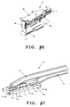
- Figure 6 is a perspective view of the device of Figure 5; and
- Figure 7 is a perspective view of the sensor element used in the device of Figures 5-6.
- Referring to the drawings, 10 in Figure 1 indicates a preferred embodiment of the novel and improved temperature sensor device of the invention which is shown to include an
electrical circuit substrate 12 having a thermally-responsive element 14 mounted on the substrate to provide an electrical signal corresponding to a temperature sensed by the device and havingsensor lead wires 16 extending from the sensor for electrically connecting the device in a temperature-monitoring circuit or the like outside the sensor device. - In a preferred embodiment of the invention, the
electrical circuit substrate 12 has threelayers substrate layer 18 extending along one side of the substrate is formed of a metal material such as copper or aluminum or the like of relatively high thermal conductivity and is typically provided flat and with sufficient thickness to be relatively rigid or at least shape-retaining. One side 18.1 of the metal substrate base layer is adapted to be disposed against asurface 24 whose temperature is to be monitored as is diagrammatically indicated in Figure 1. Thesubstrate layer 20 is formed of an electrically-conducting metal material such as copper or aluminum or the like and is typically much thinner than themetal base layer 18 of the substrate. Thesubstrate layer 22 is formed of an electrically insulating material which is secured to themetal substrate layers layer 20 from themetal base layer 18. Preferably the electrically-insulatingintermediate layer 22 comprises an electrically-insulating organic binder material such as a thermoplastic which is directly adherent to an opposite side 18.2 of the metal base layer and to one corresponding side 20.1 of the electrically-conducting substrate layer. Preferably the intermediate layer has a multiplicity of thermally-conducting particles of alumina or the like dispersed in the binder material (as is diagrammatically indicated in Figure 1 by stippling of the substrate layer 22) for enhancing thermal conductivity through the electrically insulatinglayer 22 between themetal substrate layers substrate 12 are not further described herein and it will be understood that the substrate includes a thermally-conducting metal base layer along one substrate side, an electrically-conducting metal layer along an opposite substrate side, and an electrically-insulating intermediate layer, the intermediate layer preferably comprising an organic binder adherent to each of the metal layers and accommodating a dispersion of thermally-conducting particles through the binder. - Preferably the electrically-conducting
layer 20 of the substrate is initially incorporated as a thin metal sheet or film and is then etched or otherwise formed to define an electrical circuit on the substrate to be electrically insulated by thelayer 22 from themetal base layer 18 of the substrate. Thelayer 22 is typically thin and has a thickness selected to provide a desired level of electrical insulation of thelayer 20 from themetal base 18. Preferably thesubstrate layer 20 defines a pair of metal terminal pads 20.2 at or adjacent one end 12.1 of the substrate, defines an additional pair of metal terminal pads 20.3 at or adjacent an opposite end 12.2 of the substrate spaced from the terminal pads 20.2, and defines a pair of relatively long and narrow metal circuit pads 20.4 which extend between the respective terminal pads 20.2 and corresponding terminal pads 20.3 on the substrate. In that arrangement, the metal terminal pads 20.2 are thermally isolated to a substantial extent from the metal terminal pads 20.3 by the substantial spacing between the pairs of terminal pads. In a preferred embodiment as shown in Figure 1, the pads 20.2 are spaced along a longitudinal axis of thedevice 10 near the substrate end 12.1. - In accordance with the invention, the thermally-
responsive element 14 is surface-mounted on the pair of terminal pads 20.2 at one end of the substrate. Preferably, for example, the thermally-responsive element comprises a thermistor such as a resistor 14.1 of negative temperature coefficient of resistivity which is enclosed within a cylindrical glass sleeve 14.2 and electrically connected at its opposite ends to input and output terminals 14.3 comprising metal terminal cups fitted in sealed relation over respective opposite ends of the glass sleeve. Such a thermally-responsive thermistor element is commercially available from the Keystone Carbon Co. under the designation Style 2 Glass-Encapsulated Thermistor. The metal terminal cups are soldered directly to respective ones of the pair of metal terminal pads 20.2 defined by the electrically-conductingsubstrate layer 20 as is indicated at 26. The pair oflead wires 16 each have metal wire ends 16.1 which are soldered directly to respective ones of the additional metal terminal pads 20.3 as is indicated at 28, are coated over a substantial part of their length with an electrically insulating wire coating 16.2, and extend from the substrate to permit opposite ends 16.3 of the leads to be adapted to be connected in a temperature-monitoring electrical circuit or the like as is diagrammatically indicated at 30 in Figure 1. - In that arrangement, the
substrate 12 and thermally-responsive element 14 are each of inexpensive, commercially available structure, and are each easily and economically assembled together to form thetemperature sensor 10. The device is adapted to be made in volume in automated manufacture. The thermally-responsive element 14 is securely connected to the electrically-conductingsubstrate layer 20 defining the sensor circuit, and the surface-mounted element is disposed in close thermal coupling to thesubstrate base layer 18 to be easily disposed in close heat-transfer relation to asurface 24 whose temperature is to be monitored. That is, themetal substrate layer 18 serves to collect heat from thesurface 24 and to conduct that heat through the electrically-insulatingsubstrate layer 22 to themetal substrate layer 20 and to the metal terminal cups of the thermally-responsive element 14 via thesolder 26, the thermally-conducting particles of aluminum or the like in the intermediate facilitating and enhancing this heat transfer. The ends 16.3 of the sensor lead wires are adapted to be easily connected into a temperature-monitoring circuit or the like, and the spacing of the terminal pads 20.3 from the terminal pads 20.2 thermally isolate the thermally-responsive element 14 from any heat transfer or withdrawal which might otherwise tend to be effected along the length of thelead wires 16. - In another preferred embodiment of the invention as indicated at 32 in Figure 2, wherein corresponding components are identified with corresponding reference numerals, a thermally-insulating
housing 34 is secured to thesubstrate 12 and to thelead wires 16 for enclosing the thermally-responsive element 14 while leaving the metalsubstrate base layer 18 exposed to be disposed in close heat-transfer relation to asurface 24 to be temperature-monitored. Preferably, for example, the housing comprises a cup-shaped body of glass-filled nylon material or the like having a rim 34.1 fitted to the substrate around the thermally-responsive element and having an opening 34.2 fitted around thelead wires 16 leaving the lead wire ends 16.3 extending from the housing. Preferably an epoxy adhesive or the like seals the housing rim to the substrate and seals the lead wire insulating coatings to the housing within the housing opening as indicated at 36 in Figure 2. - In other preferred embodiments of the invention as illustrated at 38 and 40 respectively in Figures 3 and 4, wherein corresponding components are identified with corresponding reference numerals, a plastic
encapsulating material 42 as shown in Figure 3 or anepoxy potting compound 44 as shown in Figure 4 are formed around the thermally-responsive element 14 and thelead wires 16 in adherent relation to thesubstrates 12 for enclosing theelements 14 in sealed relation within the temperature sensors while disposing the metalsubstrate base layers 18 to be disposed in heat-transfer relation to a temperature-monitoredsurface 24. - Various other modifications of the temperature sensors as above-described are possible within the scope of the invention. For example, the base layer of the sensor substrate is desirably formed of a composite metal material, typically a metal composite having portions of one metal of relatively high thermal conductivity extending between the opposite sides 18.1 and 18.2 of the base layer through portions of another metal of relatively low coefficient of thermal expansion. Further, other well-known thermally-responsive elements such as ceramic thermistors and the like are used in the temperature sensor within the scope of the invention.
- In another preferred embodiment of the invention as indicated at 46 in Figures 5-7, wherein corresponding components are identified with corresponding reference numerals, a C-
shaped housing 48 of a nylon material or the like has ends 48.1 of the C-shape adhered to ends of a substrate 12a in adevice 10a as best shown with reference to Figure 7 to protect the thermallyresponsive element 14 in the device. In thatdevice 10a, the terminal pads 20.2a are electrically connected to the terminals 14.3 of the thermistor and the terminal pads 20.3a connected to the lead wires are disposed at respective opposite ends of the substrate 12a. The lead wires extend from a common end of the device as shown and one of the lead wires passes over the thermistor in spaced relation to it. In that arrangement, the wire insulation tends to prevent heating effects from the wires being transferred to the thermistor and, as in the previous embodiments, the large volume of the heat-collecting base of the substrate dominates heat-transfer to the thermistor so the thermistor responds primarily to theat-transfered from thesurface 24 to be monitored. The housing has grooves 48.2 formed in an edge of one end of the C-shape receiving the lead wires therein. If desired the grooves 48.2 have widths which are somewhat reduced at the open ends of the grooves so that, when the lead wires are pressed into the grooves,
they are retained in the grooves by the smaller open groove ends. If desired, ametal spring clip 50 of stainless steel or the like is attached to thedevice 46 to grip a tube, for example, as indicated bybroken lines 52 in Figure 5 to secure thebase layer 18 in close heat-collecting relation to the tube along a line extending along and closely adjacent to the temperature-responsive element 14. If desired, the space within the C-shape is filled with a potting compound or the like (not shown). - It should be understood that although particular embodiments of the invention are illustrated herein, the invention includes all modifications and equivalents of the disclosed embodiments falling within the scope of the appended claims.
Claims (7)
- A low-cost highly-responsive surface temperature sensor comprising a substrate having a heat-collecting base layer of metal material of relatively high thermal conductivity having one side thereof to be disposed against a surface whose temperature is to be monitored, having an intermediate layer of electrically-insulating material having one side thereof secured to an opposite side of the metal base layer, and having an electrically-conducting metal layer secured to an opposite side of the intermediate layer defining an electrical circuit, and an element responsive to temperature to provide an electrical signal corresponding to the temperature, the element having input and output terminals surface-mounted to metal terminal pads defined in the circuit by the electrically-conducting layer to provide the electrical signal to the circuit.
- A temperature sensor according to claim 1 wherein the electrically-conducting layer defines the metal terminal pads at one end of the opposite intermediate layer side and defines additional metal terminal pads in the circuit at an opposite end of the opposite intermediate layer side to connected to lead wires for connecting the sensor circuit outside the sensor while thermally isolating the lead wires to a substantial extent from the temperature-responsive element.
- A temperature sensor according to claim 2 having lead wires connected to the additional metal terminal pads and extending from the substrate, and having a thermally-insulating housing sealed to the lead wires and to the substrate around the thermally-responsive element to enclose the element while exposing said one side of the base layer to be disposed against the surface whose temperature is to be monitored.
- A low-cost highly-responsive surface temperature sensor comprising a substrate having a flat, rigid heat-collecting base layer of metal material of relatively high thermal conductivity having one side thereof to be disposed against a surface whose temperature is to be monitored, having an intermediate layer of electrically-insulating material having one side thereof adherent to an opposite side of the metal base layer, the intermediate layer including a binder material adhering the intermediate layer to the base layer and thermally-conducting particles dispersed in the binder material enhancing thermal conductivity through the intermediate layer, and having an electrically-conducting metal layer relatively much thinner than the metal base layer adhered to an opposite side of the intermediate layer by the binder material defining first metal terminal pads at one end of the opposite intermediate layer side, additional metal terminal pads at an opposite end of the opposite intermediate layer side, and metal electrical circuit paths interconnecting the first and additional metal terminals pads; an element responsive to temperature to provide an electrical signal corresponding to the temperature, the element having metal input and output terminals directly soldered to the first metal terminal pads; lead wires connected to the additional metal terminal pads and extending from the substrate; and a thermally-insulating housing sealed to the lead wires and to the substrate around the thermally-responsive element to enclose the element while exposing said one base layer side to be disposed against a surface whose temperature is to be monitored.
- A temperature sensor according to claim 4 wherein the temperature-responsive element comprises a thermistor having metal input and output terminals spaced at opposite ends of the thermistor soldered directly to the first metal terminal pads defined by the electrically-conducting substrate layer.
- A temperature sensor according to claim 5 wherein the housing comprises a molded plastic member having a rim fitted against the substrate around the element and having an opening through which the lead wires extend from the additional substrate terminal pads, and adhesive means sealing the housing rim to the substrate and the lead wires to the housing in the housing opening.
- A temperature sensor according to claim 5 wherein the housing comprises an electrically insulating potting material adherent to the substrate and lead wires around the thermally-responsive element.
Applications Claiming Priority (2)
| Application Number | Priority Date | Filing Date | Title |
|---|---|---|---|
| US07/812,232 US5372427A (en) | 1991-12-19 | 1991-12-19 | Temperature sensor |
| US812232 | 1991-12-19 |
Publications (1)
| Publication Number | Publication Date |
|---|---|
| EP0547750A1 true EP0547750A1 (en) | 1993-06-23 |
Family
ID=25208942
Family Applications (1)
| Application Number | Title | Priority Date | Filing Date |
|---|---|---|---|
| EP92309864A Withdrawn EP0547750A1 (en) | 1991-12-19 | 1992-10-28 | Temperature sensor |
Country Status (3)
| Country | Link |
|---|---|
| US (1) | US5372427A (en) |
| EP (1) | EP0547750A1 (en) |
| JP (1) | JPH05264367A (en) |
Cited By (9)
| Publication number | Priority date | Publication date | Assignee | Title |
|---|---|---|---|---|
| DE19802296A1 (en) * | 1997-09-20 | 1999-03-25 | Temperaturmestechnik Geraberg | Thermometer probe for measuring surface temperatures with electronic temperature-sensitive sensor element |
| WO2000047963A1 (en) * | 1999-02-10 | 2000-08-17 | Holzschuh Gmbh + Co. Kg | Sensor and method for its production |
| DE29913950U1 (en) * | 1999-08-10 | 2000-12-21 | David & Baader DBK Spezialfabrik elektrischer Apparate und Heizwiderstände GmbH, 76870 Kandel | Temperature sensor |
| EP1568978A1 (en) * | 2004-02-24 | 2005-08-31 | Siemens Aktiengesellschaft | Temperature sensor |
| WO2014204383A1 (en) | 2013-06-17 | 2014-12-24 | Ge Healthcare Bio-Sciences Ab | A temperature sensor means and a bioreactor system comprising a temperature sensor means |
| CN108801489A (en) * | 2018-06-22 | 2018-11-13 | 苏州大学 | temperature sensor and preparation method thereof |
| EP3421955A1 (en) * | 2017-06-30 | 2019-01-02 | Pgt Thermprozesstechnik Gmbh | Method of making an electrical sensor, moulded part and electrical sensor with moulded part |
| EP3486625A1 (en) * | 2017-11-17 | 2019-05-22 | Tyco Electronics (Shanghai) Co. Ltd. | Heat conductive assembly and temperature measuring device |
| DE112013005730B4 (en) | 2012-11-30 | 2021-09-09 | Uchiya Thermostat Co., Ltd. | Temperature sensor |
Families Citing this family (178)
| Publication number | Priority date | Publication date | Assignee | Title |
|---|---|---|---|---|
| US5695285A (en) * | 1994-08-05 | 1997-12-09 | Ssi Technologies, Inc. | Apparatus for containing a temperature sensing device |
| JP3305941B2 (en) * | 1996-01-22 | 2002-07-24 | 株式会社村田製作所 | Electronic components |
| US6081182A (en) * | 1996-11-22 | 2000-06-27 | Matsushita Electric Industrial Co., Ltd. | Temperature sensor element and temperature sensor including the same |
| US6899456B2 (en) * | 1998-04-16 | 2005-05-31 | Seagate Technology Llc | Glide head for asperity detection |
| US6354736B1 (en) * | 1999-03-24 | 2002-03-12 | Honeywell International Inc. | Wide temperature range RTD |
| US6341892B1 (en) * | 2000-02-03 | 2002-01-29 | George Schmermund | Resistance thermometer probe |
| DE10051558C2 (en) * | 2000-10-18 | 2003-04-17 | Sitronic Elektrotech Ausruest | Sensor unit with an air humidity sensor and with an air temperature sensor |
| US7381184B2 (en) | 2002-11-05 | 2008-06-03 | Abbott Diabetes Care Inc. | Sensor inserter assembly |
| AU2003303597A1 (en) | 2002-12-31 | 2004-07-29 | Therasense, Inc. | Continuous glucose monitoring system and methods of use |
| US8771183B2 (en) | 2004-02-17 | 2014-07-08 | Abbott Diabetes Care Inc. | Method and system for providing data communication in continuous glucose monitoring and management system |
| US8066639B2 (en) | 2003-06-10 | 2011-11-29 | Abbott Diabetes Care Inc. | Glucose measuring device for use in personal area network |
| US20190357827A1 (en) | 2003-08-01 | 2019-11-28 | Dexcom, Inc. | Analyte sensor |
| US7920906B2 (en) | 2005-03-10 | 2011-04-05 | Dexcom, Inc. | System and methods for processing analyte sensor data for sensor calibration |
| US7299082B2 (en) | 2003-10-31 | 2007-11-20 | Abbott Diabetes Care, Inc. | Method of calibrating an analyte-measurement device, and associated methods, devices and systems |
| USD914881S1 (en) | 2003-11-05 | 2021-03-30 | Abbott Diabetes Care Inc. | Analyte sensor electronic mount |
| CA3110101A1 (en) | 2004-06-04 | 2005-12-15 | Abbott Diabetes Care Inc. | Systems and methods for managing diabetes care data |
| US8989833B2 (en) | 2004-07-13 | 2015-03-24 | Dexcom, Inc. | Transcutaneous analyte sensor |
| US9788771B2 (en) | 2006-10-23 | 2017-10-17 | Abbott Diabetes Care Inc. | Variable speed sensor insertion devices and methods of use |
| US9636450B2 (en) | 2007-02-19 | 2017-05-02 | Udo Hoss | Pump system modular components for delivering medication and analyte sensing at seperate insertion sites |
| US8333714B2 (en) | 2006-09-10 | 2012-12-18 | Abbott Diabetes Care Inc. | Method and system for providing an integrated analyte sensor insertion device and data processing unit |
| US8545403B2 (en) | 2005-12-28 | 2013-10-01 | Abbott Diabetes Care Inc. | Medical device insertion |
| US8029441B2 (en) | 2006-02-28 | 2011-10-04 | Abbott Diabetes Care Inc. | Analyte sensor transmitter unit configuration for a data monitoring and management system |
| US7731657B2 (en) | 2005-08-30 | 2010-06-08 | Abbott Diabetes Care Inc. | Analyte sensor introducer and methods of use |
| US20090105569A1 (en) | 2006-04-28 | 2009-04-23 | Abbott Diabetes Care, Inc. | Introducer Assembly and Methods of Use |
| US9572534B2 (en) | 2010-06-29 | 2017-02-21 | Abbott Diabetes Care Inc. | Devices, systems and methods for on-skin or on-body mounting of medical devices |
| US7697967B2 (en) | 2005-12-28 | 2010-04-13 | Abbott Diabetes Care Inc. | Method and apparatus for providing analyte sensor insertion |
| US9351669B2 (en) | 2009-09-30 | 2016-05-31 | Abbott Diabetes Care Inc. | Interconnect for on-body analyte monitoring device |
| US7883464B2 (en) | 2005-09-30 | 2011-02-08 | Abbott Diabetes Care Inc. | Integrated transmitter unit and sensor introducer mechanism and methods of use |
| US8512243B2 (en) | 2005-09-30 | 2013-08-20 | Abbott Diabetes Care Inc. | Integrated introducer and transmitter assembly and methods of use |
| US9743862B2 (en) | 2011-03-31 | 2017-08-29 | Abbott Diabetes Care Inc. | Systems and methods for transcutaneously implanting medical devices |
| US10226207B2 (en) | 2004-12-29 | 2019-03-12 | Abbott Diabetes Care Inc. | Sensor inserter having introducer |
| US9259175B2 (en) | 2006-10-23 | 2016-02-16 | Abbott Diabetes Care, Inc. | Flexible patch for fluid delivery and monitoring body analytes |
| US8571624B2 (en) | 2004-12-29 | 2013-10-29 | Abbott Diabetes Care Inc. | Method and apparatus for mounting a data transmission device in a communication system |
| US9398882B2 (en) | 2005-09-30 | 2016-07-26 | Abbott Diabetes Care Inc. | Method and apparatus for providing analyte sensor and data processing device |
| US8112240B2 (en) | 2005-04-29 | 2012-02-07 | Abbott Diabetes Care Inc. | Method and apparatus for providing leak detection in data monitoring and management systems |
| CA2620586A1 (en) | 2005-08-31 | 2007-03-08 | Boris P. Kovatchev | Improving the accuracy of continuous glucose sensors |
| US9521968B2 (en) | 2005-09-30 | 2016-12-20 | Abbott Diabetes Care Inc. | Analyte sensor retention mechanism and methods of use |
| US8880138B2 (en) | 2005-09-30 | 2014-11-04 | Abbott Diabetes Care Inc. | Device for channeling fluid and methods of use |
| US7766829B2 (en) | 2005-11-04 | 2010-08-03 | Abbott Diabetes Care Inc. | Method and system for providing basal profile modification in analyte monitoring and management systems |
| US11298058B2 (en) | 2005-12-28 | 2022-04-12 | Abbott Diabetes Care Inc. | Method and apparatus for providing analyte sensor insertion |
| US7736310B2 (en) | 2006-01-30 | 2010-06-15 | Abbott Diabetes Care Inc. | On-body medical device securement |
| US7826879B2 (en) | 2006-02-28 | 2010-11-02 | Abbott Diabetes Care Inc. | Analyte sensors and methods of use |
| US7885698B2 (en) | 2006-02-28 | 2011-02-08 | Abbott Diabetes Care Inc. | Method and system for providing continuous calibration of implantable analyte sensors |
| US9675290B2 (en) | 2012-10-30 | 2017-06-13 | Abbott Diabetes Care Inc. | Sensitivity calibration of in vivo sensors used to measure analyte concentration |
| US8473022B2 (en) | 2008-01-31 | 2013-06-25 | Abbott Diabetes Care Inc. | Analyte sensor with time lag compensation |
| US8226891B2 (en) | 2006-03-31 | 2012-07-24 | Abbott Diabetes Care Inc. | Analyte monitoring devices and methods therefor |
| US8374668B1 (en) | 2007-10-23 | 2013-02-12 | Abbott Diabetes Care Inc. | Analyte sensor with lag compensation |
| US7653425B2 (en) | 2006-08-09 | 2010-01-26 | Abbott Diabetes Care Inc. | Method and system for providing calibration of an analyte sensor in an analyte monitoring system |
| US8140312B2 (en) | 2007-05-14 | 2012-03-20 | Abbott Diabetes Care Inc. | Method and system for determining analyte levels |
| US7618369B2 (en) | 2006-10-02 | 2009-11-17 | Abbott Diabetes Care Inc. | Method and system for dynamically updating calibration parameters for an analyte sensor |
| US9392969B2 (en) | 2008-08-31 | 2016-07-19 | Abbott Diabetes Care Inc. | Closed loop control and signal attenuation detection |
| US7801582B2 (en) | 2006-03-31 | 2010-09-21 | Abbott Diabetes Care Inc. | Analyte monitoring and management system and methods therefor |
| US8346335B2 (en) | 2008-03-28 | 2013-01-01 | Abbott Diabetes Care Inc. | Analyte sensor calibration management |
| US7620438B2 (en) | 2006-03-31 | 2009-11-17 | Abbott Diabetes Care Inc. | Method and system for powering an electronic device |
| US8478557B2 (en) | 2009-07-31 | 2013-07-02 | Abbott Diabetes Care Inc. | Method and apparatus for providing analyte monitoring system calibration accuracy |
| US8219173B2 (en) | 2008-09-30 | 2012-07-10 | Abbott Diabetes Care Inc. | Optimizing analyte sensor calibration |
| US8224415B2 (en) | 2009-01-29 | 2012-07-17 | Abbott Diabetes Care Inc. | Method and device for providing offset model based calibration for analyte sensor |
| US7630748B2 (en) | 2006-10-25 | 2009-12-08 | Abbott Diabetes Care Inc. | Method and system for providing analyte monitoring |
| US20080071158A1 (en) | 2006-06-07 | 2008-03-20 | Abbott Diabetes Care, Inc. | Analyte monitoring system and method |
| US8135548B2 (en) | 2006-10-26 | 2012-03-13 | Abbott Diabetes Care Inc. | Method, system and computer program product for real-time detection of sensitivity decline in analyte sensors |
| US8121857B2 (en) | 2007-02-15 | 2012-02-21 | Abbott Diabetes Care Inc. | Device and method for automatic data acquisition and/or detection |
| US20080199894A1 (en) | 2007-02-15 | 2008-08-21 | Abbott Diabetes Care, Inc. | Device and method for automatic data acquisition and/or detection |
| US8930203B2 (en) | 2007-02-18 | 2015-01-06 | Abbott Diabetes Care Inc. | Multi-function analyte test device and methods therefor |
| US8732188B2 (en) | 2007-02-18 | 2014-05-20 | Abbott Diabetes Care Inc. | Method and system for providing contextual based medication dosage determination |
| US8123686B2 (en) | 2007-03-01 | 2012-02-28 | Abbott Diabetes Care Inc. | Method and apparatus for providing rolling data in communication systems |
| EP2137637A4 (en) | 2007-04-14 | 2012-06-20 | Abbott Diabetes Care Inc | Method and apparatus for providing data processing and control in medical communication system |
| US10111608B2 (en) | 2007-04-14 | 2018-10-30 | Abbott Diabetes Care Inc. | Method and apparatus for providing data processing and control in medical communication system |
| CA2683962C (en) | 2007-04-14 | 2017-06-06 | Abbott Diabetes Care Inc. | Method and apparatus for providing data processing and control in medical communication system |
| WO2008130895A2 (en) | 2007-04-14 | 2008-10-30 | Abbott Diabetes Care, Inc. | Method and apparatus for providing dynamic multi-stage signal amplification in a medical device |
| US9615780B2 (en) | 2007-04-14 | 2017-04-11 | Abbott Diabetes Care Inc. | Method and apparatus for providing data processing and control in medical communication system |
| ES2461090T3 (en) | 2007-04-14 | 2014-05-16 | Abbott Diabetes Care Inc. | Procedure and apparatus for providing data treatment and control in a medical communication system |
| US8461985B2 (en) | 2007-05-08 | 2013-06-11 | Abbott Diabetes Care Inc. | Analyte monitoring system and methods |
| US7928850B2 (en) | 2007-05-08 | 2011-04-19 | Abbott Diabetes Care Inc. | Analyte monitoring system and methods |
| US8665091B2 (en) | 2007-05-08 | 2014-03-04 | Abbott Diabetes Care Inc. | Method and device for determining elapsed sensor life |
| US8456301B2 (en) | 2007-05-08 | 2013-06-04 | Abbott Diabetes Care Inc. | Analyte monitoring system and methods |
| US8600681B2 (en) | 2007-05-14 | 2013-12-03 | Abbott Diabetes Care Inc. | Method and apparatus for providing data processing and control in a medical communication system |
| US8444560B2 (en) | 2007-05-14 | 2013-05-21 | Abbott Diabetes Care Inc. | Method and apparatus for providing data processing and control in a medical communication system |
| US10002233B2 (en) | 2007-05-14 | 2018-06-19 | Abbott Diabetes Care Inc. | Method and apparatus for providing data processing and control in a medical communication system |
| US8103471B2 (en) | 2007-05-14 | 2012-01-24 | Abbott Diabetes Care Inc. | Method and apparatus for providing data processing and control in a medical communication system |
| US8239166B2 (en) | 2007-05-14 | 2012-08-07 | Abbott Diabetes Care Inc. | Method and apparatus for providing data processing and control in a medical communication system |
| US7996158B2 (en) | 2007-05-14 | 2011-08-09 | Abbott Diabetes Care Inc. | Method and apparatus for providing data processing and control in a medical communication system |
| US8260558B2 (en) | 2007-05-14 | 2012-09-04 | Abbott Diabetes Care Inc. | Method and apparatus for providing data processing and control in a medical communication system |
| US8560038B2 (en) | 2007-05-14 | 2013-10-15 | Abbott Diabetes Care Inc. | Method and apparatus for providing data processing and control in a medical communication system |
| US9125548B2 (en) | 2007-05-14 | 2015-09-08 | Abbott Diabetes Care Inc. | Method and apparatus for providing data processing and control in a medical communication system |
| WO2008150917A1 (en) | 2007-05-31 | 2008-12-11 | Abbott Diabetes Care, Inc. | Insertion devices and methods |
| US8597188B2 (en) | 2007-06-21 | 2013-12-03 | Abbott Diabetes Care Inc. | Health management devices and methods |
| WO2008157821A1 (en) | 2007-06-21 | 2008-12-24 | Abbott Diabetes Care, Inc. | Health monitor |
| US8160900B2 (en) | 2007-06-29 | 2012-04-17 | Abbott Diabetes Care Inc. | Analyte monitoring and management device and method to analyze the frequency of user interaction with the device |
| US7768386B2 (en) | 2007-07-31 | 2010-08-03 | Abbott Diabetes Care Inc. | Method and apparatus for providing data processing and control in a medical communication system |
| US8834366B2 (en) | 2007-07-31 | 2014-09-16 | Abbott Diabetes Care Inc. | Method and apparatus for providing analyte sensor calibration |
| CA2602748A1 (en) * | 2007-09-14 | 2009-03-14 | Intelligent Devices Inc. | Environment monitoring and recording tag with remote sensing capability |
| US8216138B1 (en) | 2007-10-23 | 2012-07-10 | Abbott Diabetes Care Inc. | Correlation of alternative site blood and interstitial fluid glucose concentrations to venous glucose concentration |
| US8409093B2 (en) | 2007-10-23 | 2013-04-02 | Abbott Diabetes Care Inc. | Assessing measures of glycemic variability |
| US8377031B2 (en) | 2007-10-23 | 2013-02-19 | Abbott Diabetes Care Inc. | Closed loop control system with safety parameters and methods |
| US20090164239A1 (en) | 2007-12-19 | 2009-06-25 | Abbott Diabetes Care, Inc. | Dynamic Display Of Glucose Information |
| EP2982383B1 (en) | 2008-04-10 | 2019-05-15 | Abbott Diabetes Care, Inc. | Method for sterilizing an analyte sensor |
| US8591410B2 (en) | 2008-05-30 | 2013-11-26 | Abbott Diabetes Care Inc. | Method and apparatus for providing glycemic control |
| US8924159B2 (en) | 2008-05-30 | 2014-12-30 | Abbott Diabetes Care Inc. | Method and apparatus for providing glycemic control |
| US7826382B2 (en) | 2008-05-30 | 2010-11-02 | Abbott Diabetes Care Inc. | Close proximity communication device and methods |
| US8876755B2 (en) | 2008-07-14 | 2014-11-04 | Abbott Diabetes Care Inc. | Closed loop control system interface and methods |
| US8734422B2 (en) | 2008-08-31 | 2014-05-27 | Abbott Diabetes Care Inc. | Closed loop control with improved alarm functions |
| US9943644B2 (en) | 2008-08-31 | 2018-04-17 | Abbott Diabetes Care Inc. | Closed loop control with reference measurement and methods thereof |
| US20100057040A1 (en) | 2008-08-31 | 2010-03-04 | Abbott Diabetes Care, Inc. | Robust Closed Loop Control And Methods |
| US8622988B2 (en) | 2008-08-31 | 2014-01-07 | Abbott Diabetes Care Inc. | Variable rate closed loop control and methods |
| US8986208B2 (en) | 2008-09-30 | 2015-03-24 | Abbott Diabetes Care Inc. | Analyte sensor sensitivity attenuation mitigation |
| US9326707B2 (en) | 2008-11-10 | 2016-05-03 | Abbott Diabetes Care Inc. | Alarm characterization for analyte monitoring devices and systems |
| US8103456B2 (en) | 2009-01-29 | 2012-01-24 | Abbott Diabetes Care Inc. | Method and device for early signal attenuation detection using blood glucose measurements |
| US9402544B2 (en) | 2009-02-03 | 2016-08-02 | Abbott Diabetes Care Inc. | Analyte sensor and apparatus for insertion of the sensor |
| WO2010121084A1 (en) | 2009-04-15 | 2010-10-21 | Abbott Diabetes Care Inc. | Analyte monitoring system having an alert |
| WO2010121229A1 (en) | 2009-04-16 | 2010-10-21 | Abbott Diabetes Care Inc. | Analyte sensor calibration management |
| US9226701B2 (en) | 2009-04-28 | 2016-01-05 | Abbott Diabetes Care Inc. | Error detection in critical repeating data in a wireless sensor system |
| US8368556B2 (en) | 2009-04-29 | 2013-02-05 | Abbott Diabetes Care Inc. | Method and system for providing data communication in continuous glucose monitoring and management system |
| EP2425209A4 (en) | 2009-04-29 | 2013-01-09 | Abbott Diabetes Care Inc | METHOD AND SYSTEM FOR PROVIDING REAL-TIME ANALYTE SENSOR CALIBRATION WITH RETROSPECTIVE FILLING |
| US8597274B2 (en) | 2009-05-22 | 2013-12-03 | Abbott Diabetes Care Inc. | Usability features for integrated insulin delivery system |
| WO2010138856A1 (en) | 2009-05-29 | 2010-12-02 | Abbott Diabetes Care Inc. | Medical device antenna systems having external antenna configurations |
| US8613892B2 (en) | 2009-06-30 | 2013-12-24 | Abbott Diabetes Care Inc. | Analyte meter with a moveable head and methods of using the same |
| EP3689237B1 (en) | 2009-07-23 | 2021-05-19 | Abbott Diabetes Care, Inc. | Method of manufacturing and system for continuous analyte measurement |
| EP2473099A4 (en) | 2009-08-31 | 2015-01-14 | Abbott Diabetes Care Inc | ANALYTICAL SUBSTANCE MONITORING SYSTEM AND METHODS OF MANAGING ENERGY AND NOISE |
| WO2011026147A1 (en) | 2009-08-31 | 2011-03-03 | Abbott Diabetes Care Inc. | Analyte signal processing device and methods |
| WO2011025549A1 (en) | 2009-08-31 | 2011-03-03 | Abbott Diabetes Care Inc. | Medical devices and methods |
| ES3031591T3 (en) | 2009-08-31 | 2025-07-09 | Abbott Diabetes Care Inc | Displays for a medical device |
| EP2482720A4 (en) | 2009-09-29 | 2014-04-23 | Abbott Diabetes Care Inc | Method and apparatus for providing notification function in analyte monitoring systems |
| US8185181B2 (en) | 2009-10-30 | 2012-05-22 | Abbott Diabetes Care Inc. | Method and apparatus for detecting false hypoglycemic conditions |
| USD924406S1 (en) | 2010-02-01 | 2021-07-06 | Abbott Diabetes Care Inc. | Analyte sensor inserter |
| WO2011112753A1 (en) | 2010-03-10 | 2011-09-15 | Abbott Diabetes Care Inc. | Systems, devices and methods for managing glucose levels |
| CA2766685A1 (en) | 2010-03-24 | 2011-12-29 | Abbott Diabetes Care Inc. | Medical device inserters and processes of inserting and using medical devices |
| CN102235914B (en) * | 2010-04-30 | 2013-02-20 | 台达电子工业股份有限公司 | Temperature sensing module and its auxiliary fixing seat body |
| US8635046B2 (en) | 2010-06-23 | 2014-01-21 | Abbott Diabetes Care Inc. | Method and system for evaluating analyte sensor response characteristics |
| US11064921B2 (en) | 2010-06-29 | 2021-07-20 | Abbott Diabetes Care Inc. | Devices, systems and methods for on-skin or on-body mounting of medical devices |
| US10092229B2 (en) | 2010-06-29 | 2018-10-09 | Abbott Diabetes Care Inc. | Calibration of analyte measurement system |
| US8523430B2 (en) * | 2010-07-28 | 2013-09-03 | Lattron Co. Ltd. | Ultra thin temperature sensor device |
| EP2624745A4 (en) | 2010-10-07 | 2018-05-23 | Abbott Diabetes Care, Inc. | Analyte monitoring devices and methods |
| KR101841520B1 (en) | 2010-12-07 | 2018-03-23 | 알리손 트랜스미션, 인크. | Energy storage system for hybrid electric vehicle |
| CA3115682C (en) | 2011-02-28 | 2025-10-07 | Abbott Diabetes Care Inc. | Devices, systems, and methods associated with analyte monitoring devices and devices incorporating the same |
| US10136845B2 (en) | 2011-02-28 | 2018-11-27 | Abbott Diabetes Care Inc. | Devices, systems, and methods associated with analyte monitoring devices and devices incorporating the same |
| US9848809B2 (en) | 2011-04-15 | 2017-12-26 | Dexcom, Inc. | Advanced analyte sensor calibration and error detection |
| US9974472B2 (en) | 2011-06-16 | 2018-05-22 | Abbott Diabetes Care Inc. | Temperature-compensated analyte monitoring devices, systems, and methods thereof |
| US8870455B2 (en) * | 2011-09-15 | 2014-10-28 | Jeffrey N. Daily | Temperature sensing assembly for measuring temperature of a surface of a structure |
| US8905635B2 (en) | 2011-09-30 | 2014-12-09 | Honeywell International Inc. | Temperature sensor attachment facilitating thermal conductivity to a measurement point and insulation from a surrounding environment |
| US8901432B2 (en) | 2011-09-30 | 2014-12-02 | Honeywell International Inc. | Mitigation of block bending in a ring laser gyroscope caused by thermal expansion or compression of a circuit board |
| US9069536B2 (en) | 2011-10-31 | 2015-06-30 | Abbott Diabetes Care Inc. | Electronic devices having integrated reset systems and methods thereof |
| WO2013066849A1 (en) | 2011-10-31 | 2013-05-10 | Abbott Diabetes Care Inc. | Model based variable risk false glucose threshold alarm prevention mechanism |
| EP2775918B1 (en) | 2011-11-07 | 2020-02-12 | Abbott Diabetes Care Inc. | Analyte monitoring device and methods |
| US8710993B2 (en) | 2011-11-23 | 2014-04-29 | Abbott Diabetes Care Inc. | Mitigating single point failure of devices in an analyte monitoring system and methods thereof |
| US9317656B2 (en) | 2011-11-23 | 2016-04-19 | Abbott Diabetes Care Inc. | Compatibility mechanisms for devices in a continuous analyte monitoring system and methods thereof |
| WO2013078426A2 (en) | 2011-11-25 | 2013-05-30 | Abbott Diabetes Care Inc. | Analyte monitoring system and methods of use |
| WO2013090215A2 (en) | 2011-12-11 | 2013-06-20 | Abbot Diabetes Care Inc. | Analyte sensor devices, connections, and methods |
| EP2890297B1 (en) | 2012-08-30 | 2018-04-11 | Abbott Diabetes Care, Inc. | Dropout detection in continuous analyte monitoring data during data excursions |
| US9968306B2 (en) | 2012-09-17 | 2018-05-15 | Abbott Diabetes Care Inc. | Methods and apparatuses for providing adverse condition notification with enhanced wireless communication range in analyte monitoring systems |
| US9907492B2 (en) | 2012-09-26 | 2018-03-06 | Abbott Diabetes Care Inc. | Method and apparatus for improving lag correction during in vivo measurement of analyte concentration with analyte concentration variability and range data |
| US9474475B1 (en) | 2013-03-15 | 2016-10-25 | Abbott Diabetes Care Inc. | Multi-rate analyte sensor data collection with sample rate configurable signal processing |
| US10076285B2 (en) | 2013-03-15 | 2018-09-18 | Abbott Diabetes Care Inc. | Sensor fault detection using analyte sensor data pattern comparison |
| US10433773B1 (en) | 2013-03-15 | 2019-10-08 | Abbott Diabetes Care Inc. | Noise rejection methods and apparatus for sparsely sampled analyte sensor data |
| RU2683203C2 (en) | 2013-12-31 | 2019-03-26 | Эбботт Дайабитиз Кэр Инк. | Self-powered analyte sensor and devices using the same |
| WO2015153482A1 (en) | 2014-03-30 | 2015-10-08 | Abbott Diabetes Care Inc. | Method and apparatus for determining meal start and peak events in analyte monitoring systems |
| AU2016260547B2 (en) | 2015-05-14 | 2020-09-03 | Abbott Diabetes Care Inc. | Compact medical device inserters and related systems and methods |
| US10213139B2 (en) | 2015-05-14 | 2019-02-26 | Abbott Diabetes Care Inc. | Systems, devices, and methods for assembling an applicator and sensor control device |
| EP3319518B1 (en) | 2015-07-10 | 2025-08-13 | Abbott Diabetes Care Inc. | System and device of dynamic glucose profile response to physiological parameters |
| JP2017103278A (en) * | 2015-11-30 | 2017-06-08 | キヤノン株式会社 | Printed wiring board, electronic device provided with the printed wiring board, and soldering method in the printed wiring board |
| CN206177474U (en) * | 2016-08-12 | 2017-05-17 | 泰科电子(上海)有限公司 | Thermometric component and electrical equipment |
| CN115444410B (en) | 2017-01-23 | 2025-08-15 | 雅培糖尿病护理公司 | Applicator and assembly for insertion into an in vivo analyte sensor |
| EP4621804A3 (en) | 2017-03-21 | 2025-12-10 | Abbott Diabetes Care, Inc. | Methods, devices and system for providing diabetic condition diagnosis and therapy |
| EP3928687B1 (en) | 2017-10-24 | 2024-06-26 | Dexcom, Inc. | Wearable device with pre-connected analyte sensor |
| US11331022B2 (en) | 2017-10-24 | 2022-05-17 | Dexcom, Inc. | Pre-connected analyte sensors |
| JP7057937B2 (en) * | 2018-01-12 | 2022-04-21 | 公立大学法人大阪 | Flexible temperature sensor |
| US11525739B2 (en) * | 2018-05-08 | 2022-12-13 | Texas Instruments Incorporated | Thermistor die-based thermal probe |
| WO2020131159A1 (en) | 2018-12-21 | 2020-06-25 | Abbott Diabetes Care Inc. | Systems, devices, and methods for analyte sensor insertion |
| JP7124725B2 (en) * | 2019-01-21 | 2022-08-24 | 三菱マテリアル株式会社 | Temperature sensor and its manufacturing method |
| JP2020148590A (en) * | 2019-03-13 | 2020-09-17 | 株式会社オートネットワーク技術研究所 | Temperature measurement unit, mounting structure of temperature measurement unit, and power storage module |
| DE102019108307B4 (en) * | 2019-03-29 | 2026-04-30 | Vertiv S.R.L. | Temperature sensor for point measurements |
| US11408779B2 (en) | 2019-06-03 | 2022-08-09 | Daily Thermetrics Corporation | Temperature sensor and methods of use |
| USD1002852S1 (en) | 2019-06-06 | 2023-10-24 | Abbott Diabetes Care Inc. | Analyte sensor device |
| KR102290524B1 (en) * | 2019-07-01 | 2021-08-17 | 주식회사 이큐셀 | Sensor Mounted Wafer And Manufacturing Method Thereof |
| WO2021236071A1 (en) * | 2020-05-19 | 2021-11-25 | Hewlett-Packard Development Company, L.P. | Fluid movement monitoring |
| CN115942909A (en) | 2020-08-31 | 2023-04-07 | 雅培糖尿病护理公司 | Systems, devices, and methods for analyte sensor insertion |
| ES3000715T3 (en) | 2020-09-15 | 2025-03-03 | Abbott Diabetes Care Inc | Device for analyte monitoring |
| USD999913S1 (en) | 2020-12-21 | 2023-09-26 | Abbott Diabetes Care Inc | Analyte sensor inserter |
| MY202051A (en) | 2021-07-16 | 2024-03-30 | Abbott Diabetes Care Inc | Systems, devices, and methods for analyte monitoring |
Citations (7)
| Publication number | Priority date | Publication date | Assignee | Title |
|---|---|---|---|---|
| EP0082768A2 (en) * | 1981-12-23 | 1983-06-29 | L.C.C.-C.I.C.E. - Compagnie Europeenne De Composants Electroniques | Temperature detector and device incorporating the same |
| JPS5937433A (en) * | 1982-08-26 | 1984-02-29 | Matsushita Electric Ind Co Ltd | Temperature sensor |
| DE3717248A1 (en) * | 1986-05-23 | 1987-11-26 | Murata Manufacturing Co | Chip-like thermistor having a negative temperature coefficient |
| EP0305027A2 (en) * | 1987-08-27 | 1989-03-01 | Bowthorpe Components Limited | Temperature probe |
| EP0359007A2 (en) * | 1988-08-26 | 1990-03-21 | Nec Corporation | Structure for temperature detection in integrated circuit package |
| US4993142A (en) * | 1989-06-19 | 1991-02-19 | Dale Electronics, Inc. | Method of making a thermistor |
| EP0413902A1 (en) * | 1989-08-21 | 1991-02-27 | Nkk Corporation | Apparatus for temperature measurement |
Family Cites Families (16)
| Publication number | Priority date | Publication date | Assignee | Title |
|---|---|---|---|---|
| US3147457A (en) * | 1961-08-02 | 1964-09-01 | Fisher Scientific Co | Temperature probe |
| US3754201A (en) * | 1967-02-24 | 1973-08-21 | Moore Products Co | Heat sensitive detector |
| US3508185A (en) * | 1967-05-25 | 1970-04-21 | Leonid Naumovich Tulchinsky | Thermistor for measuring surface temperature |
| US3835434A (en) * | 1973-06-04 | 1974-09-10 | Sprague Electric Co | Ptc resistor package |
| US4129848A (en) * | 1975-09-03 | 1978-12-12 | Raytheon Company | Platinum film resistor device |
| US4037082A (en) * | 1976-04-30 | 1977-07-19 | Murata Manufacturing Co., Ltd. | Positive temperature coefficient semiconductor heating device |
| GB1503872A (en) * | 1977-02-03 | 1978-03-15 | Rosemount Eng Co Ltd | Resistance thermometer sensors |
| US4242659A (en) * | 1979-10-15 | 1980-12-30 | Leeds & Northrup Company | Thin film resistance thermometer detector probe assembly |
| US4424507A (en) * | 1981-04-10 | 1984-01-03 | Matsushita Electric Industrial Co., Ltd. | Thin film thermistor |
| DE3127726A1 (en) * | 1981-07-14 | 1983-02-03 | Robert Bosch Gmbh, 7000 Stuttgart | Measuring (sensing) probe for measuring the temperature of a medium |
| JPS5852534A (en) * | 1981-09-24 | 1983-03-28 | Junkosha Co Ltd | Temperature detecting apparatus |
| DE3325381A1 (en) * | 1983-07-14 | 1985-01-31 | Kernforschungsanlage Jülich GmbH, 5170 Jülich | NOISE THERMOMETER / THERMOCOUPLE SENSOR AND CABLE FOR CONNECTION TO THE SENSOR |
| US4560973A (en) * | 1983-11-15 | 1985-12-24 | Daimler-Benz Aktiengesellschaft | Rod shaped thermometer and method of making same |
| US4810563A (en) * | 1986-03-14 | 1989-03-07 | The Bergquist Company | Thermally conductive, electrically insulative laminate |
| US4841274A (en) * | 1987-12-21 | 1989-06-20 | Therm-O-Disc, Incorporated | Temperature responsive probe apparatus |
| US5046857A (en) * | 1990-05-23 | 1991-09-10 | General Motors Corporation | Plastic thermal probe assembly with press fit sensor |
-
1991
- 1991-12-19 US US07/812,232 patent/US5372427A/en not_active Expired - Fee Related
-
1992
- 1992-10-28 EP EP92309864A patent/EP0547750A1/en not_active Withdrawn
- 1992-12-18 JP JP4338967A patent/JPH05264367A/en active Pending
Patent Citations (7)
| Publication number | Priority date | Publication date | Assignee | Title |
|---|---|---|---|---|
| EP0082768A2 (en) * | 1981-12-23 | 1983-06-29 | L.C.C.-C.I.C.E. - Compagnie Europeenne De Composants Electroniques | Temperature detector and device incorporating the same |
| JPS5937433A (en) * | 1982-08-26 | 1984-02-29 | Matsushita Electric Ind Co Ltd | Temperature sensor |
| DE3717248A1 (en) * | 1986-05-23 | 1987-11-26 | Murata Manufacturing Co | Chip-like thermistor having a negative temperature coefficient |
| EP0305027A2 (en) * | 1987-08-27 | 1989-03-01 | Bowthorpe Components Limited | Temperature probe |
| EP0359007A2 (en) * | 1988-08-26 | 1990-03-21 | Nec Corporation | Structure for temperature detection in integrated circuit package |
| US4993142A (en) * | 1989-06-19 | 1991-02-19 | Dale Electronics, Inc. | Method of making a thermistor |
| EP0413902A1 (en) * | 1989-08-21 | 1991-02-27 | Nkk Corporation | Apparatus for temperature measurement |
Non-Patent Citations (1)
| Title |
|---|
| PATENT ABSTRACTS OF JAPAN vol. 8, no. 137 (P-282)(1574) 26 June 1984 & JP-A-59 37 433 ( MATSUSHITA DENKI SANGYO ) 29 February 1984 * |
Cited By (12)
| Publication number | Priority date | Publication date | Assignee | Title |
|---|---|---|---|---|
| DE19802296A1 (en) * | 1997-09-20 | 1999-03-25 | Temperaturmestechnik Geraberg | Thermometer probe for measuring surface temperatures with electronic temperature-sensitive sensor element |
| WO2000047963A1 (en) * | 1999-02-10 | 2000-08-17 | Holzschuh Gmbh + Co. Kg | Sensor and method for its production |
| DE29913950U1 (en) * | 1999-08-10 | 2000-12-21 | David & Baader DBK Spezialfabrik elektrischer Apparate und Heizwiderstände GmbH, 76870 Kandel | Temperature sensor |
| EP1568978A1 (en) * | 2004-02-24 | 2005-08-31 | Siemens Aktiengesellschaft | Temperature sensor |
| DE112013005730B4 (en) | 2012-11-30 | 2021-09-09 | Uchiya Thermostat Co., Ltd. | Temperature sensor |
| WO2014204383A1 (en) | 2013-06-17 | 2014-12-24 | Ge Healthcare Bio-Sciences Ab | A temperature sensor means and a bioreactor system comprising a temperature sensor means |
| CN105431720A (en) * | 2013-06-17 | 2016-03-23 | 通用电气健康护理生物科学股份公司 | A temperature sensor means and a bioreactor system comprising a temperature sensor means |
| EP3011290A4 (en) * | 2013-06-17 | 2017-03-22 | GE Healthcare Bio-Sciences AB | A temperature sensor means and a bioreactor system comprising a temperature sensor means |
| US10023833B2 (en) | 2013-06-17 | 2018-07-17 | Ge Healthcare Bio-Sciences Ab | Temperature sensor means and a bioreactor system comprising a temperature sensor means |
| EP3421955A1 (en) * | 2017-06-30 | 2019-01-02 | Pgt Thermprozesstechnik Gmbh | Method of making an electrical sensor, moulded part and electrical sensor with moulded part |
| EP3486625A1 (en) * | 2017-11-17 | 2019-05-22 | Tyco Electronics (Shanghai) Co. Ltd. | Heat conductive assembly and temperature measuring device |
| CN108801489A (en) * | 2018-06-22 | 2018-11-13 | 苏州大学 | temperature sensor and preparation method thereof |
Also Published As
| Publication number | Publication date |
|---|---|
| US5372427A (en) | 1994-12-13 |
| JPH05264367A (en) | 1993-10-12 |
Similar Documents
| Publication | Publication Date | Title |
|---|---|---|
| US5372427A (en) | Temperature sensor | |
| JP3725296B2 (en) | Temperature sensor with measuring resistor | |
| GB1573235A (en) | Heated sensor for use on aircraft and a method of making such a sensor | |
| US4808960A (en) | Thermal cutoff heater | |
| US4246786A (en) | Fast response temperature sensor and method of making | |
| EP0375262A2 (en) | Electrothermal sensor | |
| US4246787A (en) | Fast response temperature sensor and method of making | |
| EP0322338A2 (en) | High temperature sensing apparatus | |
| US4134095A (en) | Fast response temperature sensor | |
| EP0305027A2 (en) | Temperature probe | |
| US4419652A (en) | Temperature sensor | |
| CA1111471A (en) | Detachable electronic temperature control probe for electrically heated utensils | |
| CA1100235A (en) | Air temperature sensor connection assembly | |
| CN215338620U (en) | Sensor assembly | |
| EP0116680B1 (en) | A temperature-compensated crystal resonator unit | |
| US4174512A (en) | Fast response temperature sensor | |
| JPH0120664Y2 (en) | ||
| JP3007342U (en) | PTC thermistor for temperature detection | |
| JPS61108103A (en) | Positive characteristic thermistor device | |
| KR200250373Y1 (en) | Close-adhesion type thin-film temperature sensor | |
| CA1110779A (en) | Fast response temperature sensor | |
| JPS595922Y2 (en) | Chip parts with lead wires | |
| JPH0125300Y2 (en) | ||
| JPS6347157A (en) | Thermal print head | |
| SU1323885A1 (en) | Thermoelectric pressure transducer |
Legal Events
| Date | Code | Title | Description |
|---|---|---|---|
| PUAI | Public reference made under article 153(3) epc to a published international application that has entered the european phase |
Free format text: ORIGINAL CODE: 0009012 |
|
| AK | Designated contracting states |
Kind code of ref document: A1 Designated state(s): DE FR GB IT NL |
|
| 18D | Application deemed to be withdrawn |
Effective date: 19931224 |