EP0550227B1 - Commande de l'alimentation d'un ruban encreur à frappe multiple - Google Patents
Commande de l'alimentation d'un ruban encreur à frappe multiple Download PDFInfo
- Publication number
- EP0550227B1 EP0550227B1 EP92311604A EP92311604A EP0550227B1 EP 0550227 B1 EP0550227 B1 EP 0550227B1 EP 92311604 A EP92311604 A EP 92311604A EP 92311604 A EP92311604 A EP 92311604A EP 0550227 B1 EP0550227 B1 EP 0550227B1
- Authority
- EP
- European Patent Office
- Prior art keywords
- cassette
- printing apparatus
- magnetisation
- orientation
- ribbon
- Prior art date
- Legal status (The legal status is an assumption and is not a legal conclusion. Google has not performed a legal analysis and makes no representation as to the accuracy of the status listed.)
- Expired - Lifetime
Links
Images


Classifications
-
- B—PERFORMING OPERATIONS; TRANSPORTING
- B41—PRINTING; LINING MACHINES; TYPEWRITERS; STAMPS
- B41J—TYPEWRITERS; SELECTIVE PRINTING MECHANISMS, i.e. MECHANISMS PRINTING OTHERWISE THAN FROM A FORME; CORRECTION OF TYPOGRAPHICAL ERRORS
- B41J35/00—Other apparatus or arrangements associated with, or incorporated in, ink-ribbon mechanisms
- B41J35/36—Alarms, indicators, or feed disabling devices responsive to ink ribbon breakage or exhaustion
-
- B—PERFORMING OPERATIONS; TRANSPORTING
- B41—PRINTING; LINING MACHINES; TYPEWRITERS; STAMPS
- B41J—TYPEWRITERS; SELECTIVE PRINTING MECHANISMS, i.e. MECHANISMS PRINTING OTHERWISE THAN FROM A FORME; CORRECTION OF TYPOGRAPHICAL ERRORS
- B41J33/00—Apparatus or arrangements for feeding ink ribbons or like character-size impression-transfer material
- B41J33/14—Ribbon-feed devices or mechanisms
- B41J33/40—Ribbon-feed devices or mechanisms with arrangements for reversing the feed direction
- B41J33/42—Ribbon-feed devices or mechanisms with arrangements for reversing the feed direction manually
Definitions
- This invention relates to control of the feed of multi-strike ink ribbons and in particular to the control of insertion of cassettes containing such ribbons into printing apparatus.
- Multi-strike ink ribbons are ribbons in which a part of the ink is removed in a pass of the ribbon past a print head so that the ribbon may be re-used a number of times in which the ink is successively removed.
- thermal ink transfer ribbons the ink is in multiple layers carried on a backing substrate and in each pass of the ribbon ink from the exposed layer is removed leaving ink in underlying layers to be removed in successive passes of the ribbon.
- printing devices in which printing is carried out during feeding of an item, on which printing is to be effected, past a print head in a single direction it has been required that, when the end of the ribbon is reached after a pass of the ribbon, printing is interrupted to enable the entire ribbon to be rewound.
- Ink ribbons may be provided in a cassette which may be removably inserted in operative position in a printing device.
- the cassette usually has a supply spool filled with ribbon and an empty take-up spool onto which the used ribbon is wound.
- means in the printing device draws the ribbon from the supply spool past the print head of the printing device and take up spool is driven by a drive motor in the printing device to wind the used ribbon onto the take-up spool.
- GB-A-2 219 553 discloses an ink ribbon cassette provided with identifying coding in the form of a magnetised element which is sensed by printing apparatus when the cassette is mounted in said apparatus.
- printing apparatus including a print head (18); an ink ribbon cassette removably mounted relative to said print head; said cassette including first and second spools, and a multi-strike ink ribbon initially wound on one of said first and second spools, the ink ribbon being drawn from the one spool past the print head and wound onto the other of said first and second spools in printing operations; a magnetised element carried by said cassette; sensor means responsive, when the cassette is mounted relative to said print head, to magnetisation of said magnetised element to generate a signal indicative of said magnetisation characterised in that the cassette is mountable in a first orientation relative to the print head to enable the ink ribbon to be drawn from the first spool and wound onto the second spool and in a second orientation, reversed relative to said first orientation, to enable the ink ribbon to be drawn from the second spool and wound onto the first spool; in that initially the magnetised element has a first polarity of magnetisation and the sensor means generates a first signal when the cassette is mounted
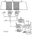
- a chassis 10 of printing apparatus has a recess 11 for the reception of an ink ribbon cassette 12.
- the cassette has a supply spool 13 filled with thermal transfer ink ribbon 19 and the ribbon extends to a take-up spool 14.
- the take spool drivingly engages with a shaft 15 of a take-up motor drive 16.
- the ribbon between the supply spool and the take-up spool is guided by ribbon guides 17 to follow a path past a thermal print head 18.
- the cassette is apertured in side walls thereof to permit the print head to enter the space between the spools when the cassette is inserted in the printing apparatus.
- the cassette When the end of the ribbon on the supply spool is reached the cassette is removed and may be replaced on the printing apparatus with reverse orientation so that the spool which was the take-up spool and on which the entire ribbon is now wound becomes the supply spool and the spool which was the supply spool and has become empty becomes the take-up spool.
- This removal, reversal and re-insertion of the cassette may be repeated a number of times until the ink layers of the multi-strike ribbon have been depleted.
- a user of the printing apparatus may in error replace the cassette in the printing apparatus with the same orientation as in its previous insertion or may continue to re-insert the cassette with reversed orientations after the ink layers have been depleted.
- this would merely be an inconvenience and would lead to poor quality printing which could be remedied by repeating the printing process with a new ribbon.
- postage franking apparatus this could result in mail items passing through the apparatus without receiving a clear and perceivable franking impression. Accordingly for such apparatus it is desirable to provide means which prevent or at least warn an operator that the cassette has an incorrect orientation or has been used to a predetermined limit.
- a magnetisable element 20 is provided in or on the cassette. Initially the element 20 is magnetised with a predetermined first polarity.
- the printing apparatus is provided with a sensor 21, which may be a Hall effect device, which responds to the magnetisation of the element of a cassette inserted in the printing apparatus.
- the Hall effect device 21 is powered by connections to 0V and +VCC lines and has an output connected to a voltage sense circuit 22.
- An output 23 of the circuit 22 is connected to a control circuit 24 which may be a microprocessor.
- the output of the device 21 causes the voltage sensor circuit to produce a first signal on output line 23 to the control circuit 24.
- the control circuit inhibits operation of the printing apparatus 26 for printing and preferably causes display of an error message to an operator of the apparatus.
- An electromagnet 25 is located on the chassis of the printing apparatus adjacent the magnetisable element 20 of an inserted cassette 12.
- the electromagnet is normally unenergised. Energisation of the electromagnet is controlled by the control circuit 24.
- an end of ribbon sensor 27 inputs a signal to the control circuit and the control circuit energises the electromagnet to remagnetise the element 20 with a polarity reversed compared with the previous polarity of magnetisation.
- the positions of the spools will be interchanged and the reversed polarity of magnetisation of element 20 will correspond, relative to the chassis of the printing apparatus, to its initial polarisation and be detected by the sensor device 21 to cause the circuit 22 to output the first signal to the control circuit. Accordingly the printing apparatus will be operative.
- the cassette were to be re-inserted without reversal of its orientation the polarity of magnetisation of the element 20 would be sensed as being reversed and the control circuit would inhibit operation of the printing apparatus 26.
- the control circuit 24 may include a counter which is reset to zero by a reset input 28 generated for example by manual operation of a key by the operator when a new unused ribbon cassette is inserted and the counter is incremented each time the sensor 21 detects that the cassette is re-inserted with reversed orientation.
- the control circuit will include means to check the count registered by the counter and when it reaches a value corresponding to a limit to re-use of the ribbon the control circuit inhibits further operation of the printing apparatus until a new cassette is inserted and the counter is reset.
- the electromagnet is energised when the end of ribbon is reached in order to reverse polarity of magnetisation of the element 20.
- the electromagnet is not energised and hence the element will remain magnetised with a polarity which prevents the printing apparatus accepting the cassette for further use.
- the end of ribbon detector is provided in the printing apparatus to determine when the end of the ribbon has been reached in unwinding from one of the spools and the end of ribbon detector provides an end of ribbon indication to the control circuit 24.
- both magnetisable elements 30, 31 are magnetised with a predetermined polarity.
- the polarity of magnetisation of both elements is sensed by sensors 32, 33 and upon sensing of the predetermined polarity of magnetisation of both elements the counter of the control circuit is reset to zero and one element, for example element 30, is magnetised by an electromagnet 34 to reverse its polarity of magnetisation.
- the polarity of magnetisation of both elements 30, 31 remains unchanged. It will be appreciated that two sensor devices 32, 33 are provided for sensing the two magnetisable elements 30, 31. On sensing the polarity of magnetisation of the elements, the sensed polarity is retained either by the voltage sense circuits 35, 36 or by the control circuit 24. When the cassette is removed and re-inserted the polarity of magnetisation of both elements is sensed and if the sensed polarity is reversed as compared with the sensed polarity retained from the previous insertion of the cassette an indication is provided that the cassette has been reversed. However if the sensed polarity is not reversed it indicates that the cassette has not been reversed and operation of the printing apparatus 26 is inhibited until the cassette has been re-inserted with reversed orientation.
- the magnetisable element 20 and elements 30, 31 are illustrated schematically as rod like elements. However they may be of other form and may comprise a length of magnetisable tape, such as magnetic recording tape utilised for recording signals, and may be secured to a surface of the cassette by adhesive. It will be appreciated that the sensor devices 21, 32, 33 are located at a position on the chassis of the printing apparatus such that each sensor is responsive to the polarity of magnetisation of the element adjacent thereto. Also the electromagnetic 25 or 34 is so located as to be able to reverse the polarity of magnetisation of the element adjacent thereto.
- the thermal transfer ink ribbon may carry a magnetisable element in the form of a magnetisable ribbon at each end of the thermal ink ribbon.
- the magnetisable ribbon is drawn from the spool it passes a sensor which is responsive to the magnetisation of the ribbon.
- the magnetisable element is magnetised such that the whole element is magnetised with a desired polarity of magnetisation.
- the element may be magnetised with a code representation which signifies the number of times the cassette has been reversed. Each time the cassette is reversed the code is incremented to signify the updated number of reversals of the cassette.
- the electromagnet 25 includes a number of sections which may be selectively energised to magnetise the element 20 with the code representation and the sensor 21 is responsive to the code representation.
Landscapes
- Impression-Transfer Materials And Handling Thereof (AREA)
Claims (8)
- Appareil d'impression comprenant une tête d'impression (18) ; une cassette à ruban encreur (12) montée de manière amovible par rapport à la tête d'impression ; cette cassette comprenant une première bobine et une seconde bobine (13, 14) ainsi qu'un ruban encreur à frappe multiple (19) enroulé initialement autour de l'une de la première et de la seconde bobine, ce ruban encreur étant tiré de l'une des bobines pour passer devant la tête d'impression et s'enrouler sur l'autre de la première et de la seconde bobine au cours des opérations d'impression ; un élément magnétisé (20) porté par la cassette ; des moyens de capteur (21) répondant, lorsque la cassette est montée par rapport à la tête d'impression, à la magnétisation de l'élément magnétisé pour générer un signal indiquant cette magnétisation, caractérisé en ce quela cassette (12) peut se monter dans une première orientation par rapport à la tête d'impression (18) pour permettre au ruban encreur (19) d'être tiré de la première bobine (13) et de s'enrouler sur la seconde bobine (14) et, dans une seconde orientation, inversée par rapport à la première orientation, pour permettre au ruban encreur (19) d'être tiré de la seconde bobine (14) et de s'enrouler sur la première bobine (13) ;initialement, l'élément magnétisé (20) a une première polarité de magnétisation et le capteur (21) génère un premier signal lorsque la cassette est montée dans la première orientation et un second signal lorsque la cassette est montée dans la seconde orientation ;des moyens de commande (24) permettent le fonctionnement de l'appareil d'impression en réponse au premier signal, et bloquent le fonctionnement de l'appareil d'impression en réponse au second signal ; etdes moyens de magnétisation (25) sont actionnés par les moyens de commande en réponse au fait que le ruban encreur est complètement dévidé de la première bobine, afin d'inverser la polarité de magnétisation de l'élément magnétisé pour que le capteur génère le second signal lorsque la cassette est montée dans la première orientation, et le premier signal lorsque la cassette est montée dans la seconde orientation.
- Appareil d'impression selon la revendication 1,
caractérisé en outre en ce que
les moyens de commande (24) comprennent un compteur incrémenté en réponse à la génération de chaque premier signal. - Appareil d'impression selon la revendication 2,
caractérisé en outre en ce que
les moyens de commande (24) servent à empêcher le fonctionnement de l'appareil d'impression (26) en réponse à une valeur prédéterminée du compte enregistré par le compteur. - Appareil d'impression selon la revendication 1,
caractérisé en outre en ce que
les moyens de commande comprennent un compteur incrémenté en réponse à la génération de chaque premier signal et servant à empêcher le fonctionnement des moyens de magnétisation (25 ; 34) en réponse à une valeur prédéterminée du compte enregistré par le compteur. - Appareil d'impression selon la revendication 1,
caractérisé en outre en ce que
les moyens de commande font fonctionner les moyens de magnétisation (25 ; 34) pour magnétiser l'élément magnétisé (20 ; 30, 31) avec une configuration de magnétisation représentant un code. - Appareil d'impression selon la revendication 5,
caractérisé en outre en ce que
les moyens de commande font fonctionner les moyens de magnétisation (25 ; 34) pour incrémenter le code à chaque fois que l'orientation de la cassette à ruban (12) est inversée par rapport à l'appareil d'impression (10, 26). - Appareil d'impression selon l'une quelconque des revendications précédentes,
dans lequel
l'élément magnétisé (20) consiste en un ruban magnétisable porté par le ruban encreur (19). - Appareil d'impression selon l'une quelconque des revendications précédentes,
caractérisé en outre en ce que
le capteur (21) consiste en un dispositif à effet Hall.
Applications Claiming Priority (2)
| Application Number | Priority Date | Filing Date | Title |
|---|---|---|---|
| GB919127478A GB9127478D0 (en) | 1991-12-30 | 1991-12-30 | Multi-strike ribbon feed control |
| GB9127478 | 1991-12-30 |
Publications (3)
| Publication Number | Publication Date |
|---|---|
| EP0550227A2 EP0550227A2 (fr) | 1993-07-07 |
| EP0550227A3 EP0550227A3 (en) | 1993-12-15 |
| EP0550227B1 true EP0550227B1 (fr) | 1998-10-21 |
Family
ID=10706889
Family Applications (1)
| Application Number | Title | Priority Date | Filing Date |
|---|---|---|---|
| EP92311604A Expired - Lifetime EP0550227B1 (fr) | 1991-12-30 | 1992-12-18 | Commande de l'alimentation d'un ruban encreur à frappe multiple |
Country Status (4)
| Country | Link |
|---|---|
| US (1) | US5340223A (fr) |
| EP (1) | EP0550227B1 (fr) |
| DE (1) | DE69227358T2 (fr) |
| GB (1) | GB9127478D0 (fr) |
Families Citing this family (6)
| Publication number | Priority date | Publication date | Assignee | Title |
|---|---|---|---|---|
| GB2297293A (en) * | 1995-01-30 | 1996-07-31 | Neopost Ltd | Controlling thermal printing parameters in postage meters in response to coded ink-ribbon cassettes |
| DE19549376A1 (de) * | 1995-03-07 | 1996-09-26 | Francotyp Postalia Gmbh | Anordnung zur Ermittlung einer Farbbandrestmenge für Thermotransferdruckverfahren |
| DE19509683C2 (de) * | 1995-03-07 | 2000-06-21 | Francotyp Postalia Gmbh | Thermotransferdruckverfahren und Anordnung zur Durchführung des Verfahrens mit Multi-Use-Farbbandkassette |
| FR2744391B1 (fr) * | 1996-02-01 | 1998-03-06 | Imaje Sa | Imprimante industrielle apte a recevoir au moins une cartouche de consommable |
| FR2782823B1 (fr) | 1998-09-01 | 2000-11-17 | Neopost Ind | Procede d'impression thermique |
| JP4463671B2 (ja) * | 2004-12-20 | 2010-05-19 | ニスカ株式会社 | インクリボンカセット及びプリンタ |
Family Cites Families (14)
| Publication number | Priority date | Publication date | Assignee | Title |
|---|---|---|---|---|
| JPS5747685A (en) * | 1980-09-03 | 1982-03-18 | Canon Inc | Printer |
| JPS59190884A (ja) * | 1983-04-14 | 1984-10-29 | Canon Inc | テープ残量検出装置 |
| JPS6071285A (ja) * | 1983-09-27 | 1985-04-23 | Fujitsu Ltd | 熱式プリンタ |
| JPS60190379A (ja) * | 1984-03-13 | 1985-09-27 | Hitachi Ltd | 熱転写プリンタ |
| JPS60219081A (ja) * | 1984-04-16 | 1985-11-01 | Hitachi Ltd | 熱転写プリンタ |
| JPH0630449Y2 (ja) * | 1986-09-08 | 1994-08-17 | ブラザー工業株式会社 | 印字装置 |
| JPS6389372A (ja) * | 1986-10-03 | 1988-04-20 | Yasuyoshi Sato | 往復二段の印字が可能なりボンカセツト |
| JPS6422972A (en) * | 1987-07-17 | 1989-01-25 | Kao Corp | Dyeing composition for keratin fiber |
| DE8713034U1 (de) * | 1987-09-28 | 1987-11-19 | Computer Gesellschaft Konstanz Mbh, 7750 Konstanz | Farbband-Kassette |
| JPH0162064U (fr) * | 1987-10-14 | 1989-04-20 | ||
| JPH01195088A (ja) * | 1988-01-30 | 1989-08-04 | Nec Home Electron Ltd | 熱写転プリンタ |
| JP2800184B2 (ja) * | 1988-06-10 | 1998-09-21 | 松下電器産業株式会社 | 感熱転写記録用受像体 |
| DE3819782A1 (de) * | 1988-06-10 | 1989-12-14 | Triumph Adler Ag | Schreibmaschine, drucker oder dergleichen und farbbandkassette hierfuer |
| JPH01314185A (ja) * | 1988-06-14 | 1989-12-19 | Sanyo Electric Co Ltd | プリンタ用リボンカセット |
-
1991
- 1991-12-30 GB GB919127478A patent/GB9127478D0/en active Pending
-
1992
- 1992-12-18 DE DE69227358T patent/DE69227358T2/de not_active Expired - Fee Related
- 1992-12-18 EP EP92311604A patent/EP0550227B1/fr not_active Expired - Lifetime
- 1992-12-21 US US07/994,525 patent/US5340223A/en not_active Expired - Lifetime
Also Published As
| Publication number | Publication date |
|---|---|
| DE69227358T2 (de) | 1999-04-29 |
| EP0550227A2 (fr) | 1993-07-07 |
| EP0550227A3 (en) | 1993-12-15 |
| DE69227358D1 (de) | 1998-11-26 |
| US5340223A (en) | 1994-08-23 |
| GB9127478D0 (en) | 1992-02-19 |
Similar Documents
| Publication | Publication Date | Title |
|---|---|---|
| EP0315384B1 (fr) | Dispositif d'avance pour ruban d'impression thermique | |
| US6082914A (en) | Thermal printer and drive system for controlling print ribbon velocity and tension | |
| US5821975A (en) | Method and apparatus for monitoring inking ribbon usage in a thermal printing process and for controlling printing dependent theron | |
| EP0376575B1 (fr) | Timbre poste et son système de distribution | |
| US4844629A (en) | Electronic labeler with printhead and web sensor combined for concurrent travel, and assemblies of identification devices therefor | |
| CN1753790B (zh) | 使用耗材的打印装置及其操作方法 | |
| US5513922A (en) | Printer having a removable control panel | |
| US4920882A (en) | Electronic labeler with printhead and web sensor combined for concurrent travel, and assemblies of identification devices therefor | |
| EP0988984B1 (fr) | Cassette contenant une bande d'impression à attacher de façon magnétique | |
| EP0550227B1 (fr) | Commande de l'alimentation d'un ruban encreur à frappe multiple | |
| EP0814960B1 (fr) | Procede pour regler le mecanisme d'enroulement d'un ruban dans un appareil d'impression | |
| EP0493944B1 (fr) | Alimentation avec un ruban encreur | |
| EP0800926B1 (fr) | Appareil et méthode pour exécuter une opération d'usinage prédéfinie sur un matériau en feuille comprenant une longueur de ruban consommable | |
| USRE42088E1 (en) | Printer | |
| US6338436B1 (en) | Variable ticket and ticket printer | |
| US5921689A (en) | Method of calibrating a ribbon winding mechanism for a printing apparatus | |
| CA1321322C (fr) | Methode et appareil de perforation d'un ruban a transfert thermique use | |
| US20050036817A1 (en) | Method and apparatus for reducing label length error in a label printer | |
| US4926193A (en) | Thermal transfer ribbon cartridge including ribbon perforating means | |
| US4767933A (en) | Optical ribbon edge sensor having means for adjusting the switch sensitivity to the selected ink color | |
| JPS5859096A (ja) | 無端帯状物体の寿命検出装置 | |
| JPH01145969A (ja) | ロール状原紙の終端検出装置 | |
| JPS6312441A (ja) | カセツト式ラベルプリンタ | |
| JPH0214426Y2 (fr) | ||
| HK1089133B (en) | A printing apparatus using consumable and operating method thereof |
Legal Events
| Date | Code | Title | Description |
|---|---|---|---|
| PUAI | Public reference made under article 153(3) epc to a published international application that has entered the european phase |
Free format text: ORIGINAL CODE: 0009012 |
|
| AK | Designated contracting states |
Kind code of ref document: A2 Designated state(s): CH DE FR GB LI |
|
| PUAL | Search report despatched |
Free format text: ORIGINAL CODE: 0009013 |
|
| AK | Designated contracting states |
Kind code of ref document: A3 Designated state(s): CH DE FR GB LI |
|
| 17P | Request for examination filed |
Effective date: 19940519 |
|
| 17Q | First examination report despatched |
Effective date: 19950608 |
|
| GRAG | Despatch of communication of intention to grant |
Free format text: ORIGINAL CODE: EPIDOS AGRA |
|
| GRAG | Despatch of communication of intention to grant |
Free format text: ORIGINAL CODE: EPIDOS AGRA |
|
| GRAH | Despatch of communication of intention to grant a patent |
Free format text: ORIGINAL CODE: EPIDOS IGRA |
|
| GRAH | Despatch of communication of intention to grant a patent |
Free format text: ORIGINAL CODE: EPIDOS IGRA |
|
| GRAA | (expected) grant |
Free format text: ORIGINAL CODE: 0009210 |
|
| AK | Designated contracting states |
Kind code of ref document: B1 Designated state(s): CH DE FR GB LI |
|
| REG | Reference to a national code |
Ref country code: CH Ref legal event code: NV Representative=s name: HEPP, WENGER & RYFFEL AG Ref country code: CH Ref legal event code: EP |
|
| REF | Corresponds to: |
Ref document number: 69227358 Country of ref document: DE Date of ref document: 19981126 |
|
| ET | Fr: translation filed | ||
| PLBE | No opposition filed within time limit |
Free format text: ORIGINAL CODE: 0009261 |
|
| STAA | Information on the status of an ep patent application or granted ep patent |
Free format text: STATUS: NO OPPOSITION FILED WITHIN TIME LIMIT |
|
| 26N | No opposition filed | ||
| REG | Reference to a national code |
Ref country code: GB Ref legal event code: IF02 |
|
| PGFP | Annual fee paid to national office [announced via postgrant information from national office to epo] |
Ref country code: CH Payment date: 20051215 Year of fee payment: 14 |
|
| PG25 | Lapsed in a contracting state [announced via postgrant information from national office to epo] |
Ref country code: LI Free format text: LAPSE BECAUSE OF NON-PAYMENT OF DUE FEES Effective date: 20061231 Ref country code: CH Free format text: LAPSE BECAUSE OF NON-PAYMENT OF DUE FEES Effective date: 20061231 |
|
| REG | Reference to a national code |
Ref country code: CH Ref legal event code: PL |
|
| PGFP | Annual fee paid to national office [announced via postgrant information from national office to epo] |
Ref country code: GB Payment date: 20071218 Year of fee payment: 16 |
|
| PGFP | Annual fee paid to national office [announced via postgrant information from national office to epo] |
Ref country code: DE Payment date: 20071221 Year of fee payment: 16 |
|
| PGFP | Annual fee paid to national office [announced via postgrant information from national office to epo] |
Ref country code: FR Payment date: 20071217 Year of fee payment: 16 |
|
| GBPC | Gb: european patent ceased through non-payment of renewal fee |
Effective date: 20081218 |
|
| REG | Reference to a national code |
Ref country code: FR Ref legal event code: ST Effective date: 20090831 |
|
| PG25 | Lapsed in a contracting state [announced via postgrant information from national office to epo] |
Ref country code: DE Free format text: LAPSE BECAUSE OF NON-PAYMENT OF DUE FEES Effective date: 20090701 |
|
| PG25 | Lapsed in a contracting state [announced via postgrant information from national office to epo] |
Ref country code: GB Free format text: LAPSE BECAUSE OF NON-PAYMENT OF DUE FEES Effective date: 20081218 |
|
| PG25 | Lapsed in a contracting state [announced via postgrant information from national office to epo] |
Ref country code: FR Free format text: LAPSE BECAUSE OF NON-PAYMENT OF DUE FEES Effective date: 20081231 |