EP0550794B1 - Codeur de rotation avec détection de valeur absolue de position - Google Patents
Codeur de rotation avec détection de valeur absolue de position Download PDFInfo
- Publication number
- EP0550794B1 EP0550794B1 EP92115147A EP92115147A EP0550794B1 EP 0550794 B1 EP0550794 B1 EP 0550794B1 EP 92115147 A EP92115147 A EP 92115147A EP 92115147 A EP92115147 A EP 92115147A EP 0550794 B1 EP0550794 B1 EP 0550794B1
- Authority
- EP
- European Patent Office
- Prior art keywords
- encoder
- rotation
- angle
- switching element
- rotation encoder
- Prior art date
- Legal status (The legal status is an assumption and is not a legal conclusion. Google has not performed a legal analysis and makes no representation as to the accuracy of the status listed.)
- Expired - Lifetime
Links
Images




Classifications
-
- H—ELECTRICITY
- H03—ELECTRONIC CIRCUITRY
- H03M—CODING; DECODING; CODE CONVERSION IN GENERAL
- H03M1/00—Analogue/digital conversion; Digital/analogue conversion
- H03M1/002—Provisions or arrangements for saving power, e.g. by allowing a sleep mode, using lower supply voltage for downstream stages, using multiple clock domains or by selectively turning on stages when needed
-
- G—PHYSICS
- G01—MEASURING; TESTING
- G01D—MEASURING NOT SPECIALLY ADAPTED FOR A SPECIFIC VARIABLE; ARRANGEMENTS FOR MEASURING TWO OR MORE VARIABLES NOT COVERED IN A SINGLE OTHER SUBCLASS; TARIFF METERING APPARATUS; MEASURING OR TESTING NOT OTHERWISE PROVIDED FOR
- G01D5/00—Mechanical means for transferring the output of a sensing member; Means for converting the output of a sensing member to another variable where the form or nature of the sensing member does not constrain the means for converting; Transducers not specially adapted for a specific variable
- G01D5/12—Mechanical means for transferring the output of a sensing member; Means for converting the output of a sensing member to another variable where the form or nature of the sensing member does not constrain the means for converting; Transducers not specially adapted for a specific variable using electric or magnetic means
- G01D5/14—Mechanical means for transferring the output of a sensing member; Means for converting the output of a sensing member to another variable where the form or nature of the sensing member does not constrain the means for converting; Transducers not specially adapted for a specific variable using electric or magnetic means influencing the magnitude of a current or voltage
-
- G—PHYSICS
- G01—MEASURING; TESTING
- G01D—MEASURING NOT SPECIALLY ADAPTED FOR A SPECIFIC VARIABLE; ARRANGEMENTS FOR MEASURING TWO OR MORE VARIABLES NOT COVERED IN A SINGLE OTHER SUBCLASS; TARIFF METERING APPARATUS; MEASURING OR TESTING NOT OTHERWISE PROVIDED FOR
- G01D5/00—Mechanical means for transferring the output of a sensing member; Means for converting the output of a sensing member to another variable where the form or nature of the sensing member does not constrain the means for converting; Transducers not specially adapted for a specific variable
- G01D5/12—Mechanical means for transferring the output of a sensing member; Means for converting the output of a sensing member to another variable where the form or nature of the sensing member does not constrain the means for converting; Transducers not specially adapted for a specific variable using electric or magnetic means
- G01D5/244—Mechanical means for transferring the output of a sensing member; Means for converting the output of a sensing member to another variable where the form or nature of the sensing member does not constrain the means for converting; Transducers not specially adapted for a specific variable using electric or magnetic means influencing characteristics of pulses or pulse trains; generating pulses or pulse trains
- G01D5/24404—Interpolation using high frequency signals
-
- G—PHYSICS
- G01—MEASURING; TESTING
- G01P—MEASURING LINEAR OR ANGULAR SPEED, ACCELERATION, DECELERATION, OR SHOCK; INDICATING PRESENCE, ABSENCE, OR DIRECTION, OF MOVEMENT
- G01P3/00—Measuring linear or angular speed; Measuring differences of linear or angular speeds
- G01P3/42—Devices characterised by the use of electric or magnetic means
- G01P3/44—Devices characterised by the use of electric or magnetic means for measuring angular speed
- G01P3/48—Devices characterised by the use of electric or magnetic means for measuring angular speed by measuring frequency of generated current or voltage
- G01P3/481—Devices characterised by the use of electric or magnetic means for measuring angular speed by measuring frequency of generated current or voltage of pulse signals
- G01P3/489—Digital circuits therefor
-
- H—ELECTRICITY
- H03—ELECTRONIC CIRCUITRY
- H03M—CODING; DECODING; CODE CONVERSION IN GENERAL
- H03M1/00—Analogue/digital conversion; Digital/analogue conversion
- H03M1/12—Analogue/digital converters
- H03M1/22—Analogue/digital converters pattern-reading type
- H03M1/24—Analogue/digital converters pattern-reading type using relatively movable reader and disc or strip
- H03M1/28—Analogue/digital converters pattern-reading type using relatively movable reader and disc or strip with non-weighted coding
- H03M1/30—Analogue/digital converters pattern-reading type using relatively movable reader and disc or strip with non-weighted coding incremental
- H03M1/308—Analogue/digital converters pattern-reading type using relatively movable reader and disc or strip with non-weighted coding incremental with additional pattern means for determining the absolute position, e.g. reference marks
Definitions
- the invention relates to an encoder for absolute value position detection according to the preamble of claim 1.
- Encoders with an absolute value position detection are usually manufactured with an angle encoder disk and corresponding optical scanning devices (with, for example, LEDs, photodiodes, etc.). With the aid of such a disk, the absolute angular position of an encoder shaft connected to this disk can be detected within an angular interval of 0 ° to 360 °. An angular range over several revolutions cannot be measured with a single disk, since its coding is naturally repeated after passing through one revolution.
- multi-turn encoders have been developed which, although they are only provided with an angle measuring device for detecting an angular range between 0 ° and 360 °, have a counting unit for detecting the completely completed revolutions.
- this combination enables the measuring range of the rotary encoder to be expanded to the maximum number of revolutions that can be detected by the counting unit, on the other hand it requires a constant power supply to the counting unit and the scanning device of the angle encoder disk. If the power supply to the counting unit is interrupted, the information it contains is lost. Switching off the power supply for the scanning device of the angular encoder also means that the counting unit can no longer register newly added or reversed revolutions. If the encoder shaft is rotated, the information about the absolute position is also lost in this case.
- the power supply of the encoder was buffered with the help of a battery or an accumulator.
- a multi-rotary encoder which has an angle coding disk with the corresponding optical detection device for detecting the absolute angle within one revolution and also comprises a separate magnetic signal transmitter and a counting unit for detecting completely completed revolutions.
- the named encoder is buffered by an external battery in the event of a power failure.
- Such a device has the disadvantage that it must always be connected at least to the auxiliary voltage supply in order not to lose the stored information.
- the encoder does not lose its information when external leads are disconnected and, furthermore, continues to record the movements of the encoder shaft. This is particularly necessary if a robot is set up for test purposes and then dismantled into individual components for delivery.
- multi-turn encoders are desirable which also record the movements and positions of the individual components after or during the disassembly of the robot, so that the individual parts of the system do not have to be readjusted after they have been reassembled.
- the invention is therefore based on the object of proposing an inexpensive multi-rotary encoder that receives its information reliably without an external power supply and detects the absolute position of the encoder shaft over a large number of revolutions.
- the buffering in the event of a suspended external power supply is intended here very generously, ie over a period of several years.
- a rotary encoder in connection with a rotatable actuating part which is fixedly connected to the encoder shaft.
- the current that flows through this switching element in the closed state is limited by a series connection with a very high resistance.
- the logic circuit for pulse shaping and pulse selection which generates a logic signal per revolution of the encoder shaft from the signal of the switching element when the actuating part rotates, and the counting unit is also designed to be very high-resistance with the aid of at least one integrated circuit. Because of the extremely reduced power consumption in this way, the buffer battery or the accumulator can be chosen to be so small that it, like the electronic circuits mentioned, can be integrated into the encoder unit.
- Such a rotary encoder provided with the components mentioned forms a compact structural unit and can function for years without an external power supply.
- a simple and robust embodiment of the invention is provided with a mechanically acting actuating part.
- Such an actuating part can be designed as a cam on the encoder shaft, which opens or closes two contact tongues with the revolutions of the encoder shaft.
- a magnetic ring which consists of a part of its circumference made of a permanent magnetic and the other part of non-magnetic material, the switching element being designed as a reed switch, which is opened or turned once when the ring is turned is closed.
- the current counter reading can be synchronized with the zero crossing of the angle measuring device.
- the counter which is coupled to the switching element which switches in the respective direction of rotation before the zero crossing of the angle measuring device, always contains the correct value at the time of the zero crossing. Depending on the direction of rotation, the data output must be switched back and forth between the two counters.
- the closing effective angular range of the actuating part should be larger than the angle ⁇ and ⁇ 'enclosed by the two switching elements.
- the switching state of one switching element can be used to suppress one pulse per revolution from the pulses associated with the other switching element. This gives exactly one signal per revolution at the output of the logic circuit for each switching element.
- a square-wave signal can be generated on an edge of a switching state of a switching element, for example with the aid of a time delay element and a logic antivalence gate.
- the time delay of the time delay element gives exactly the width of the pulse.
- Switching back and forth between the two counters is preferably carried out with the aid of a multiplexer which switches the current counter content to the data output of the encoder in time with the most significant bit of the binary number read by the angle measuring device.
- a multiplexer which switches the current counter content to the data output of the encoder in time with the most significant bit of the binary number read by the angle measuring device.
- ASIC application-specific integrated circuit
- the angle measuring device can comprise an optical, a capacitive or an inductive scanning device.
- An angular coding part which is adapted to the scanning device and which rotates with the rotary encoder shaft, for example an angular coding disk for an optical scanning device, is to be provided here.
- Fig. 1 shows a rotary encoder 1 with a rotary encoder housing 2, which consists of a stator 3 and a housing cover 4.
- a transmitter shaft 5, which is rotatably supported by ball bearings 6, passes through the stator 3 from below.
- the interior of the housing 2 is divided into an upper 8 and a lower part 9 by a shielding plate 7.
- the components are in the lower part 9 of the rotary encoder 1, which are provided for detecting the angular position within one revolution (single-turn encoder).
- these are an angle coding disk 10 which is illuminated from below by an optical transmitter unit 11.
- Above the angle encoder disk 10 is a receiver circuit board 12 which has optical sensors (not shown) and a receiver circuit.
- a magnet holder 13 which is plugged onto the encoder shaft 5.
- the part 14 of the magnet holder 13 inserted over the encoder shaft 5 passes through the shielding plate and projects into the lower part 9 of the rotary encoder 1.
- a magnetic ring 15 is attached to the magnet holder 13 at the top.
- a screw 16 fixes the magnet holder 13 on the encoder shaft 5.
- Above the magnetic ring there are two reed switches 17a, b within their shielding caps 18a, 18b.
- the two reed switches 17a, 17b are fastened on a printed circuit board 19 on which the circuits for signal shaping and selection, not shown, and the counters are constructed.
- a circuit board 20 At the top of the circuit board 19 there is a circuit board 20 with a DC voltage source and a battery 21.
- the components in the lower part 9 of the rotary encoder work in the manner known from conventional angular rotary encoders for angular resolution within one revolution of the encoder shaft 5.
- the arrangement of the two reed switches 17a, 17b in the upper part 8 of the rotary encoder is shown in the schematic plan view of FIG. 2. They are at an angle of ⁇ or ⁇ ' ⁇ 45 ° to line 22, which corresponds to the zero crossing of the angle coding disk 10.
- the magnetic ring 15 is composed of a magnetic 23a and a non-magnetic part 23b, so that the reed switches are open when the magnetic part 23a of the magnetic ring is below them and in the other case are closed.
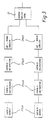
- the signals thus generated by the different switching states of the reed switches 17a, 17b are further processed in accordance with the block diagram shown in FIG. 3.
- the signals generated by the reed switches as pulse generators 17a, 17b enter an electronic circuit for pulse shaping 24, which forms a logic square pulse from each edge of its input signal. Subsequently, these square-wave pulses are selected in a circuit 25 for pulse selection in such a way that one square-wave pulse per revolution of the encoder shaft 5 is present at the output of this circuit.
- These impulses processed in this way are finally counted and stored in two counters. Since the two reed switches are at an angle .alpha. Or .alpha.
- the current counter reading of one counter precedes the actual value in a certain direction of rotation, while the counter reading of the other counter lags behind.
- the counter with the respectively correct data stock is selected and switched through synchronously with the zero crossing of the angle coding disk 10 to its output.
- FIG. 4 shows a possible circuit for signal processing according to FIG. 3.
- An external power supply 28 and a lithium battery 29 supply the operating voltage for the following circuit as required.
- the two reed switches 17a, 17b switch the two power lines 30a, 30b against the via two very high-impedance and thus current-limiting resistors 31a, 31b Circuit ground.
- the voltages Va, Vb which are present in the signal lines 32a, 32b vary.
- a time delay element 33a, 33b and an relevance gate 34a, 34b By using a time delay element 33a, 33b and an relevance gate 34a, 34b, a rectangular pulse A or B is generated at the output of the antivalence gates 34a, 34b.
- the time course of the various signals during the rotation of the encoder shaft is shown in FIG. 5.
- the top diagram shows the most significant bit MSB at the output of the single-turn encoder located in the lower part 9 of the encoder 1. This bit is set exactly with the zero crossing of the encoder shaft at time t o and switched to "Low” at 180 °.
- the two diagrams following below reflect the voltage curve Va, Vb in the signal lines 32a, 32b.
- the signal curve corresponds to that of the most significant bit MSB, but is offset by a time t ⁇ , t ⁇ ', in which the encoder shaft 5 rotates by the angles ⁇ and ⁇ '.
- the two following diagrams represent the pulses A, B at the output of the antivalence gates 34a, 34b.
- the width of the rectangular pulses A, B corresponds exactly to the time delay of the time delay elements 33a, 33b.
- the two diagrams below make it clear that only every second square-wave signal A ', B' is selected at the output of the AND gates 35. Accordingly, the lowest data bits, Da, Db of the two counters 26a, 26b are switched with the input of these square-wave signals A ', B'.
- the bottom one Based on the lowest data bit Da, Db, the diagram shows how the current counter reading in accordance with the direction of rotation, in this case Db, is output as data bit Dm synchronously with the most significant bit of the angle coding disk MSB at the output of the multiplexer 27.
- a rotary encoder according to the invention manages with buffer currents that are less than 10 ⁇ A due to the measures described. Using a small lithium battery with 0.95 Ah results in a reliable function in the event of an external power failure of approx. 10 years.
Landscapes
- Physics & Mathematics (AREA)
- General Physics & Mathematics (AREA)
- Engineering & Computer Science (AREA)
- Theoretical Computer Science (AREA)
- Transmission And Conversion Of Sensor Element Output (AREA)
Claims (10)
- Encodeur (1) pour la détection de position de valeur absolue, comportant un stator (3) et un arbre d'encodeur (5) monté de façon rotative dans le stator, l'encodeur (1) présentant un dispositif de mesure angulaire pour détecter la position précise de l'arbre d'encodeur (5) pendant un tour complet dans un intervalle angulaire de 0°-360° et une unité de sortie pour sortir la position détectée de l'arbre d'encodeur comme donnée angulaire sur une sortie de données, le dispositif de mesure angulaire et l'unité de sortie étant alimentés par une alimentation en courant externe, et l'encodeur présentant de plus un dispositif pour détecter le nombre des tours complètement parcourus présentant une première partie (17) agencée de façon résistant à la torsion et une seconde partie (15) fixée à l'arbre d'encodeur (5) et tournant avec celui-ci, et l'encodeur (1) étant muni d'un circuit logique pour former et sélectionner (24,25) une impulsion logique à partir du signal de sortie du dispositif pour détecter les tours de l'arbre d'encodeur (5) ainsi que pour détecter le sens de rotation et présentant une unité de comptage (26) dépendant du sens de rotation, qui additionne les impulsions logiques ainsi engendrées selon le sens de rotation à l'état du compteur respectif ou l'en soustrait et dont l'état du compteur actuel peut être lu sur la sortie de données, et une batterie (21) ou un accumulateur étant prévu pour maintenir l'alimentation en courant pour le dispositif pour détecter des tours entiers, le circuit logique (24,25), et l'unité de comptage (26) lors d'une interruption de l'alimentation en courant externe sinon fournie,
caractérisé en ce que le dispositif pour détecter des tours entiers présente un élément de commutation se fermant mécaniquement et une partie d'actionnement rotative liée à l'arbre d'encodeur (5) pour l'élément de commutation, en ce que, pour réduire la taille nécessaire de la batterie (21) ou de l'accumulateur pour tamponner l'encodeur (1) lors d'une panne de l'alimentation en courant externe (28), il existe un circuit (24) qui présente une résistance (31) à très haute impédance, au moins lorsque l'élément de commutation (17) est fermé, en série avec celui-ci, de sorte que le courant dans ce circuit est limité, en ce que le circuit logique (24,25) pour former les impulsions et pour sélectionner est réalisé avec au moins un circuit de commutation intégré et, de même que l'unité de comptage (26), présente une haute impédance, et en ce que le circuit logique (24, 25), l'unité de comptage (26), l'élément de commutation (15,17), ainsi que la batterie tampon (21) ou l'accumulateur sont intégrés totalement dans l'unité d'encodeur (2), de sorte que l'encodeur (1) forme, avec les composants cités, une unité constructive compacte. - Encodeur selon une des revendications précédentes,
caractérisé en ce qu'une partie d'actionnement agissant de façon mécanique est prévue pour l'actionnement de l'élément de commutation se fermant mécaniquement. - Encodeur selon la revendication 1 ou 2,
caractérisé en ce que, sur l'arbre d'encodeur (5), comme pièce d'actionnement, il est monté une bague magnétique (15) qui est constituée d'une partie agissant magnétiquement (23a) et d'une zone (23b) qui n'agit pas magnétiquement, et en ce que l'élément de commutation se fermant mécaniquement est un contact Reed (17), qui, lors de la rotation de la bague magnétique (15), de façon dépendant du fait qu'une partie agissant de façon magnétique (23a) ou une partie non agissante (23b) de la bague magnétique (15) se trouve à sa proximité, est alternativement ouvert ou fermé. - Encodeur selon une des revendications précédentes,
caractérisé en ce que la bague magnétique (15) est constituée d'une partie magnétique (23a) et d'une partie non magnétique (23b). - Encodeur selon une des revendications précédentes,
caractérisé en ce qu'il comporte deux éléments de commutation (17a,17b), qui sont agencés sous un angle de 45° par rapport au passage par zéro (22) de l'arbre d'encodeur (5), deux circuits logiques (24a,24b,25a,25b) pour engendrer des impulsions, et deux compteurs (26a,26b), et en ce que la partie agissant en fermant (23a) et la partie n'agissant pas en fermant (23b) de la pièce d'actionnement (15) sont réalisées de sorte que les éléments de commutation (17) sont commutés tous les 180° pendant la rotation de l'arbre d'encodeur (5). - Encodeur selon une des revendications précédentes,
caractérisé en ce que, à partir des différents états de commutation (Va,Vb) des éléments de commutation (17a,17b), il est engendré, au moyen d'un organe de temporisation (33) et d'une porte logique (34), une impulsion, en ce que le sens du flanc du signal (Va,Vb) sortant de l'élément de commutation (17a,17b) peut être utilisé pour commuter le mode de comptage du compteur entre l'addition et la soustraction, et en ce que la liaison de signaux (32a,32b) d'un élément de commutation (17a,17b) est commutée par une porte logique (35a,35b) et la liaison de signaux (32a,32b) de l'autre élément logique (17a,17b), de sorte que chaque seconde impulsion est supprimée et, pour un tour complet de l'arbre d'encodeur (5), uniquement une impulsion est engendrée. - Encodeur selon une des revendications précédentes,
caractérisé en ce qu'un multiplexeur (27) est prévu qui, selon le sens de rotation, connecte le contenu d'à chaque fois un compteur (26a,26b) de l'encodeur (1) en synchronisme avec le bit de valeur maximale (MSB) du code lu par le dispositif de mesure angulaire (10), sur la sortie de données de l'encodeur (1), de sorte que la valeur de donnée, se trouvant à la sortie, de l'encodeur (1) peut être synchronisée avec le passage par zéro (22) de la partie de codage angulaire (10) du dispositif de mesure angulaire sur l'arbre d'encodeur (5) pendant sa rotation. - Encodeur selon une des revendications précédentes,
caractérisé en ce que le dispositif de mesure angulaire est muni d'un dispositif de balayage optique et d'une partie de codage angulaire correspondante. - Encodeur selon une des revendications précédentes,
caractérisé en ce que le dispositif de mesure angulaire est muni d'un dispositif de balayage capacitif et d'une partie de codage angulaire correspondante. - Encodeur selon une des revendications précédentes,
caractérisé en ce que le dispositif de mesure angulaire est muni d'un dispositif de balayage inductif et d'une partie de codage angulaire correspondante.
Applications Claiming Priority (2)
| Application Number | Priority Date | Filing Date | Title |
|---|---|---|---|
| DE4139570 | 1991-11-30 | ||
| DE4139570 | 1991-11-30 |
Publications (3)
| Publication Number | Publication Date |
|---|---|
| EP0550794A2 EP0550794A2 (fr) | 1993-07-14 |
| EP0550794A3 EP0550794A3 (en) | 1994-05-25 |
| EP0550794B1 true EP0550794B1 (fr) | 1997-05-07 |
Family
ID=6446002
Family Applications (1)
| Application Number | Title | Priority Date | Filing Date |
|---|---|---|---|
| EP92115147A Expired - Lifetime EP0550794B1 (fr) | 1991-11-30 | 1992-09-04 | Codeur de rotation avec détection de valeur absolue de position |
Country Status (2)
| Country | Link |
|---|---|
| EP (1) | EP0550794B1 (fr) |
| DE (1) | DE59208457D1 (fr) |
Cited By (6)
| Publication number | Priority date | Publication date | Assignee | Title |
|---|---|---|---|---|
| DE19849108A1 (de) * | 1998-10-24 | 2000-06-08 | Fritz Kuebler Gmbh Zaehl Und S | Drehgeber |
| DE19902736A1 (de) * | 1999-01-19 | 2000-08-03 | Huebner Elektromasch Ag | Elektronischer Umdrehungszähler |
| DE10001676C1 (de) * | 2000-01-12 | 2001-08-02 | Huebner Elmasch Ag | Elektronischer Umdrehungszähler |
| DE10145884A1 (de) * | 2001-09-18 | 2003-04-30 | Hella Kg Hueck & Co | Elektronischer Winkelsensor |
| DE202008017515U1 (de) | 2008-10-27 | 2009-11-05 | Fritz Kübler GmbH Zähl- und Sensortechnik | Miniaturisierter batteriegeschützter Drehgeber |
| DE102014102564A1 (de) | 2014-02-27 | 2015-08-27 | Fritz Kübler GmbH Zähl- und Sensortechnik | Absolutwert-Singleturn-Drehgeber mit auswählbarer Multiturn-Funktion |
Families Citing this family (7)
| Publication number | Priority date | Publication date | Assignee | Title |
|---|---|---|---|---|
| DE19820014A1 (de) * | 1998-05-06 | 1999-11-11 | Heidenhain Gmbh Dr Johannes | Multiturn-Codedrehgeber |
| DE10311412B3 (de) * | 2003-03-13 | 2004-05-27 | Lenord, Bauer & Co. Gmbh | Verfahren zur Messung und Bestimmung der absoluten Position einer Geberwelle sowie einer Einrichtung zur Anwendung des Verfahrens |
| ATE373813T1 (de) * | 2004-07-12 | 2007-10-15 | Feig Electronic Gmbh | Positionsgeber sowie verfahren zur bestimmung einer position einer drehbaren welle |
| US7466125B2 (en) | 2004-07-12 | 2008-12-16 | Feig Electronic Gmbh | Position transmitter and method for determining a position of a rotating shaft |
| EP2486373B1 (fr) | 2009-10-09 | 2017-01-04 | Baumer IVO GmbH & Co. KG | Indicateur de position doté d'une détermination de position à rotation multiple |
| EP2309232B1 (fr) | 2009-10-09 | 2015-07-22 | Baumer IVO GmbH & Co. KG | Indicateur de position doté d'une détermination de position à rotation multiple |
| EP2312274A1 (fr) | 2009-10-09 | 2011-04-20 | Baumer Innotec AG | Indicateur de position doté d'une détermination de position à rotation multiple |
Family Cites Families (3)
| Publication number | Priority date | Publication date | Assignee | Title |
|---|---|---|---|---|
| DE3584256D1 (de) * | 1984-04-14 | 1991-10-31 | Fanuc Ltd | Schaltungsmittel zur auswertung der bewegung einer inkrementalcodespur. |
| JPH0641853B2 (ja) * | 1986-09-29 | 1994-06-01 | 株式会社安川電機 | 多回転式絶対値エンコ−ダ |
| US4849680A (en) * | 1986-11-07 | 1989-07-18 | Kabushiki Kaisha Empire Airport Service | Encoder |
-
1992
- 1992-09-04 DE DE59208457T patent/DE59208457D1/de not_active Expired - Lifetime
- 1992-09-04 EP EP92115147A patent/EP0550794B1/fr not_active Expired - Lifetime
Cited By (12)
| Publication number | Priority date | Publication date | Assignee | Title |
|---|---|---|---|---|
| DE19849108A1 (de) * | 1998-10-24 | 2000-06-08 | Fritz Kuebler Gmbh Zaehl Und S | Drehgeber |
| DE19849108C2 (de) * | 1998-10-24 | 2001-12-13 | Fritz Kuebler Gmbh Zaehl Und S | Drehgeber |
| DE19902736A1 (de) * | 1999-01-19 | 2000-08-03 | Huebner Elektromasch Ag | Elektronischer Umdrehungszähler |
| DE19902736C2 (de) * | 1999-01-19 | 2001-07-19 | Huebner Elmasch Ag | Elektronischer Umdrehungszähler |
| DE10001676C1 (de) * | 2000-01-12 | 2001-08-02 | Huebner Elmasch Ag | Elektronischer Umdrehungszähler |
| DE10145884A1 (de) * | 2001-09-18 | 2003-04-30 | Hella Kg Hueck & Co | Elektronischer Winkelsensor |
| DE10145884B4 (de) * | 2001-09-18 | 2005-04-14 | Hella Kgaa Hueck & Co. | Elektronischer Winkelsensor |
| DE202008017515U1 (de) | 2008-10-27 | 2009-11-05 | Fritz Kübler GmbH Zähl- und Sensortechnik | Miniaturisierter batteriegeschützter Drehgeber |
| DE102008055687A1 (de) | 2008-10-27 | 2010-05-06 | Fritz Kübler GmbH Zähl- und Sensortechnik | Miniaturisierter batteriegeschützter Drehgeber |
| DE102008055687B4 (de) * | 2008-10-27 | 2014-05-22 | Fritz Kübler GmbH Zähl- und Sensortechnik | Eingang Miniaturisierter batteriegestützter Drehgeber |
| DE102014102564A1 (de) | 2014-02-27 | 2015-08-27 | Fritz Kübler GmbH Zähl- und Sensortechnik | Absolutwert-Singleturn-Drehgeber mit auswählbarer Multiturn-Funktion |
| DE102014102564B4 (de) | 2014-02-27 | 2018-05-30 | Fritz Kübler GmbH Zähl- und Sensortechnik | Absolutwert-Singleturn-Drehgeber mit auswählbarer Multiturn-Funktion |
Also Published As
| Publication number | Publication date |
|---|---|
| EP0550794A2 (fr) | 1993-07-14 |
| EP0550794A3 (en) | 1994-05-25 |
| DE59208457D1 (de) | 1997-06-12 |
Similar Documents
| Publication | Publication Date | Title |
|---|---|---|
| DE4229610A1 (de) | Drehgeber mit absolutwert-positionserfassung | |
| DE4407474C1 (de) | Drehwinkelsensor | |
| EP0550794B1 (fr) | Codeur de rotation avec détection de valeur absolue de position | |
| EP1565755B1 (fr) | Detecteur de position | |
| EP0893668A1 (fr) | Capteur d'angle | |
| DE2246660A1 (de) | Analog-ditigal-umsetzer | |
| DE102009029431A1 (de) | Multiturn-Drehgeber | |
| DE10054470C2 (de) | Drehstellungsgeber zum Erfassen einer Drehstellung | |
| EP1676099B1 (fr) | Dispositif detecteur comprenant un capteur angulaire | |
| DE20311861U1 (de) | Vorrichtung zur Positions- und/oder Längenbestimmung | |
| EP0233618A2 (fr) | Détecteur de mouvement | |
| DE1275105B (de) | Einrichtung zum Ausgeben digitaler Winkelwerte mit einem Resolver | |
| DE3804786C2 (fr) | ||
| DE3801245C2 (fr) | ||
| DE3318351A1 (de) | Verfahren fuer eine drehzahl- und drehrichtungsabhaengige auswerteschaltung eines inkrementalen drehrichtungsimpulsgebers | |
| EP0836072B1 (fr) | Capteur de rotation | |
| DE19632656A1 (de) | Verfahren und Vorrichtung zum berührungslosen Erfassen der Lage oder der Drehstellung eines Gegenstandes | |
| DE2455440C3 (de) | Verifizierungsanordnung für ein bestimmtes Impulsmuster | |
| EP0566923B1 (fr) | Dispositif pour mesurer sans contact la position axiale d'un objet tournant | |
| DE3638569C2 (fr) | ||
| EP0855599A2 (fr) | Compas électronique | |
| DE4041491C2 (de) | Sensor zur Erzeugung von elektrischen Signalen, welche die Stellung eines Objekts wiedergeben | |
| WO1997027673A1 (fr) | Appareil de commutation electronique fonctionnant sans contact | |
| EP1391735B1 (fr) | Circuit d'évaluation pour des capteurs à circuit oscillant | |
| DE102005061347A1 (de) | Anordnung zur Messung des absoluten Drehwinkels einer Welle |
Legal Events
| Date | Code | Title | Description |
|---|---|---|---|
| PUAI | Public reference made under article 153(3) epc to a published international application that has entered the european phase |
Free format text: ORIGINAL CODE: 0009012 |
|
| AK | Designated contracting states |
Kind code of ref document: A2 Designated state(s): CH DE ES FR GB IT LI |
|
| PUAL | Search report despatched |
Free format text: ORIGINAL CODE: 0009013 |
|
| AK | Designated contracting states |
Kind code of ref document: A3 Designated state(s): CH DE ES FR GB IT LI |
|
| 17P | Request for examination filed |
Effective date: 19940903 |
|
| GRAG | Despatch of communication of intention to grant |
Free format text: ORIGINAL CODE: EPIDOS AGRA |
|
| 17Q | First examination report despatched |
Effective date: 19960806 |
|
| GRAH | Despatch of communication of intention to grant a patent |
Free format text: ORIGINAL CODE: EPIDOS IGRA |
|
| GRAH | Despatch of communication of intention to grant a patent |
Free format text: ORIGINAL CODE: EPIDOS IGRA |
|
| GRAA | (expected) grant |
Free format text: ORIGINAL CODE: 0009210 |
|
| AK | Designated contracting states |
Kind code of ref document: B1 Designated state(s): CH DE ES FR GB IT LI |
|
| PG25 | Lapsed in a contracting state [announced via postgrant information from national office to epo] |
Ref country code: ES Free format text: THE PATENT HAS BEEN ANNULLED BY A DECISION OF A NATIONAL AUTHORITY Effective date: 19970507 |
|
| REG | Reference to a national code |
Ref country code: CH Ref legal event code: EP |
|
| REF | Corresponds to: |
Ref document number: 59208457 Country of ref document: DE Date of ref document: 19970612 |
|
| REG | Reference to a national code |
Ref country code: CH Ref legal event code: NV Representative=s name: KELLER & PARTNER PATENTANWAELTE AG |
|
| GBT | Gb: translation of ep patent filed (gb section 77(6)(a)/1977) |
Effective date: 19970807 |
|
| ET | Fr: translation filed | ||
| PLBE | No opposition filed within time limit |
Free format text: ORIGINAL CODE: 0009261 |
|
| 26N | No opposition filed | ||
| REG | Reference to a national code |
Ref country code: GB Ref legal event code: IF02 |
|
| REG | Reference to a national code |
Ref country code: CH Ref legal event code: PFA Owner name: IVO GMBH & CO. Free format text: IVO IRION & VOSSELER GMBH & CO.#POSTFACH 3360, DAUCHINGER STRASSE 58-62#D-78022 VILLINGEN-SCHWENNINGEN (DE) -TRANSFER TO- IVO GMBH & CO.#POSTFACH 3360, DAUCHINGER STRASSE 58-62#78022 VILLINGEN-SCHWENNINGEN (DE) |
|
| REG | Reference to a national code |
Ref country code: FR Ref legal event code: CD |
|
| REG | Reference to a national code |
Ref country code: CH Ref legal event code: PFA Owner name: BAUMER IVO GMBH & CO. KG Free format text: IVO GMBH & CO.#POSTFACH 3360, DAUCHINGER STRASSE 58-62#78022 VILLINGEN-SCHWENNINGEN (DE) -TRANSFER TO- BAUMER IVO GMBH & CO. KG#POSTFACH 3360 DAUCHINGER STRASSE 58-62#78022 VILLINGEN-SCHWENNINGEN (DE) |
|
| REG | Reference to a national code |
Ref country code: FR Ref legal event code: CD |
|
| PGFP | Annual fee paid to national office [announced via postgrant information from national office to epo] |
Ref country code: IT Payment date: 20100915 Year of fee payment: 19 Ref country code: FR Payment date: 20101005 Year of fee payment: 19 |
|
| PGFP | Annual fee paid to national office [announced via postgrant information from national office to epo] |
Ref country code: GB Payment date: 20100929 Year of fee payment: 19 |
|
| PGFP | Annual fee paid to national office [announced via postgrant information from national office to epo] |
Ref country code: DE Payment date: 20101029 Year of fee payment: 19 |
|
| REG | Reference to a national code |
Ref country code: CH Ref legal event code: NV Representative=s name: BAUMER INNOTEC AG |
|
| PGFP | Annual fee paid to national office [announced via postgrant information from national office to epo] |
Ref country code: CH Payment date: 20110930 Year of fee payment: 20 |
|
| GBPC | Gb: european patent ceased through non-payment of renewal fee |
Effective date: 20110904 |
|
| PG25 | Lapsed in a contracting state [announced via postgrant information from national office to epo] |
Ref country code: IT Free format text: LAPSE BECAUSE OF NON-PAYMENT OF DUE FEES Effective date: 20110904 |
|
| REG | Reference to a national code |
Ref country code: FR Ref legal event code: ST Effective date: 20120531 |
|
| PG25 | Lapsed in a contracting state [announced via postgrant information from national office to epo] |
Ref country code: GB Free format text: LAPSE BECAUSE OF NON-PAYMENT OF DUE FEES Effective date: 20110904 Ref country code: FR Free format text: LAPSE BECAUSE OF NON-PAYMENT OF DUE FEES Effective date: 20110930 |
|
| REG | Reference to a national code |
Ref country code: DE Ref legal event code: R071 Ref document number: 59208457 Country of ref document: DE |
|
| REG | Reference to a national code |
Ref country code: DE Ref legal event code: R071 Ref document number: 59208457 Country of ref document: DE |
|
| REG | Reference to a national code |
Ref country code: CH Ref legal event code: PL |
|
| PG25 | Lapsed in a contracting state [announced via postgrant information from national office to epo] |
Ref country code: DE Free format text: LAPSE BECAUSE OF EXPIRATION OF PROTECTION Effective date: 20120905 |