EP0551542A1 - Ferngesteuertes Relais - Google Patents
Ferngesteuertes Relais Download PDFInfo
- Publication number
- EP0551542A1 EP0551542A1 EP92100602A EP92100602A EP0551542A1 EP 0551542 A1 EP0551542 A1 EP 0551542A1 EP 92100602 A EP92100602 A EP 92100602A EP 92100602 A EP92100602 A EP 92100602A EP 0551542 A1 EP0551542 A1 EP 0551542A1
- Authority
- EP
- European Patent Office
- Prior art keywords
- plunger
- remote controlled
- operation handle
- housing
- controlled relay
- Prior art date
- Legal status (The legal status is an assumption and is not a legal conclusion. Google has not performed a legal analysis and makes no representation as to the accuracy of the status listed.)
- Ceased
Links
Images


Classifications
-
- H—ELECTRICITY
- H01—ELECTRIC ELEMENTS
- H01H—ELECTRIC SWITCHES; RELAYS; SELECTORS; EMERGENCY PROTECTIVE DEVICES
- H01H89/00—Combinations of two or more different basic types of electric switches, relays, selectors and emergency protective devices, not covered by any single one of the other main groups of this subclass
- H01H89/06—Combination of a manual reset circuit with a contactor, i.e. the same circuit controlled by both a protective and a remote control device
- H01H89/08—Combination of a manual reset circuit with a contactor, i.e. the same circuit controlled by both a protective and a remote control device with both devices using the same contact pair
-
- H—ELECTRICITY
- H01—ELECTRIC ELEMENTS
- H01H—ELECTRIC SWITCHES; RELAYS; SELECTORS; EMERGENCY PROTECTIVE DEVICES
- H01H3/00—Mechanisms for operating contacts
- H01H3/32—Driving mechanisms, i.e. for transmitting driving force to the contacts
- H01H3/48—Driving mechanisms, i.e. for transmitting driving force to the contacts using lost-motion device
-
- H—ELECTRICITY
- H01—ELECTRIC ELEMENTS
- H01H—ELECTRIC SWITCHES; RELAYS; SELECTORS; EMERGENCY PROTECTIVE DEVICES
- H01H51/00—Electromagnetic relays
- H01H51/22—Polarised relays
- H01H51/2209—Polarised relays with rectilinearly movable armature
Definitions
- the present invention relates to an improvement of a remote controlled relay.
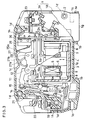
- FIG.3 is a cross-sectional side view showing a constitution of the related remote controlled relay when the relay is switched off (hereinafter abbreviated as OFF).
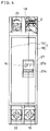
- FIG.4 is a plan view of the related remote controlled relay shown in FIG.3.
- FIG.5 is a cross-sectional side view of the related remote controlled relay when the relay is switched on (hereinafter abbreviated as ON).
- FIG.6 is a plan view of the related remote controlled relay shown in FIG.5.
- FIG.7 is a cross-sectional side view showing main parts of the related remote controlled relay in a condition shown in FIG.3.
- FIG.8 is a cross-sectional side view showing the main parts of the related remote controlled relay in the condition shown in FIG.5.
- FIG.9 is a circuit diagram showing a circuit of the typical remote controlled relay.
- a housing 1 consists of a base member 1A and a cover member 1B.
- the housing 1 has: a pair of grooves 1a formed on its both side walls 1e and 1f in the vicinity of a bottom face 1g, whereto fixing bands (not shown in the figure) are to be coupled; a pair of protrusions 1b in the vicinity of the center part of the bottom face 1g, whereby the housing 1 is to be fixed on a DIN standard rails (not shown in the figure); and an opening 1c on its top face 1h.
- the base member 1A and the cover member 1B respectively have four coupling holes 1d and four protrusions (not shown in the figure because of obviousness).
- the each hole 1d on the base member 1A are provided to face and to couple each hole formed on the protrusion of the cover member 1B.
- the base member 1A and the cover member 1B are connected and fixed by rivets 2 which are fit in the holes 1d.
- a driving magnet 3 is positioned on substantially the center of the housing 1, wherein the driving magnet 3 is provided in a manner that the moving direction of its plunger 4 is perpendicular to the bottom face 1g of the housing 1.
- the driving magnet 3 is a polarized-type one, and the plunger 4 is slidably provided on a center hole of a bobbin 6 as shown in FIGs.7 and 8, whereon an electromagnetic coil 5 is wound, and the plunger 4 has upper and lower armatures 4a, 4b on both ends.
- a first yoke 7 encloses the bobbin 6 and has an opening 7a wherefrom a rod part 4c of the plunger 4 projects upwards.
- Permanent magnets 8 are provided on inner walls of the first yoke 7, for example, at right and left hands in the figures, and both permanent magnets 8 are fixed on the first yoke 7 in a manner that one face of poles of the magnets 8 contact to the inner face of the first yoke 7.
- the other faces of the magnets 8 having the other polarity are fixed to second yokes 9 which have a channel-section.
- the second yokes 9 are provided in a manner that brim parts the bobbin 6 of the driving coil 3 are fit in the channel-section parts of the second yokes 9.
- a link 11 for transmitting the movement of the plunger 4 to a moving contact 10 is provided above the driving magnet 3.
- the link 11 is rotatively pivoted on the housing 1 by a pin 12, an end 11a of the link 11 is pin-joined to an end of the rod part 4c of the plunger 4 by a connecting pin 13.
- a moving unit 14 comprises: an insulative member 16 which is pin-jointed to an end thereof to the other end 11b of the link 11 by a pin 15; a moving base member 17 which is slidably fit in a guide groove 16a formed on the other end of the insulative member 16 and whereto the moving contact 10 is fixed; and a compression spring 18 provided in a manner to supply a pressure to the moving contact 10.
- the moving contact 10 is provided for facing to a fixed contact 20 which is fixed on a main terminal 19 whereto a main circuit is to be connected in a manner that the moving contact 10 is driven to approach to and to depart from the fixed contact 20 by movement of the moving unit 14.
- Rod-shaped protrusions 16b formed on both (forward and backward of FIG.5) of the insulative member 16 are slidably engaged in grooves (not shown) of the base member 1A and the cover member 1B, and thereby, the moving unit 14 is driven by the movement of the plunger 4 in a manner that the moving contact 10 approaches to and departs from the fixed contact 20.
- the moving base member 17 is electrically connected to another main terminal 22, whereto the main circuit is to be connected, by the shunt 21.
- a pair of remote control terminals 23 are provided on upper part of the side 1e of the housing 1 whereto wires of a remote controller are to be connected.
- One of the remote control terminals 23 is connected to a lead wire 5a of the electromagnetic coil 5 and the other remote control terminal 23 is connected to the other lead wire 5b of the coil 5 via diodes 24 and a switch 25 on a printed circuit substrate 26.
- the circuit diagram of the typical remote controlled relay is shown in FIG. 9.
- An operation handle 27 is rotatively pivoted on the housing 1 by a pin 28 on a point opposite to the link 11 against the plunger 4.
- the operation handle 27 is coupled to the rod part 4c of the plunger 4 by a coupling pin 13, wherein an end of the coupling pin 13 is press-fit in a coupling hole 29. Thereby, the operation handle 27 is rotated by reciprocative movement of the plunger 4 in directions opposite to the rotation directions of the link 11.
- the operation handle 27 has a knob 27a which is manually operated from the outside of the housing 1, and the knob 27a is positioned in the opening 1c of the housing 1 (consisting of the base member 1A and the cover member 1B).
- buttons 27b On parts of the surface of the operation handle 27 which are positioned symmetrical to the knob 27a, indications 27b (shown in FIGs.4 and 6)for indicating ON state and OFF state of the relay are provided.
- the indications 27b are observed through the opening 1c.
- the operation handle 27 has an operation part 27c which contacts an actuator 25a of the switch 25 for switching the switch 25.
- FIG.3 shows the OFF state that the remote controlled relay is switched off.
- the plunger 4 is held in a manner that the armature 4a is attracted on the bottom face of the first yoke 7 by magnetic flux of the permanent magnet 8, and the moving contact 10 and the fixed contact 20 are respectively at stable positions wherein the contacts 10 and 20 are apart from each other.
- the operation handle 27 is rotated in clockwise direction by the movement of the plunger 4 and the indication is changed from OFF to ON. In such a sequence of the operation, the operation handle 27 drives the actuator 25a of the switch 25 and thereby the switch 25 is turned on or off.
- the electromagnetic coil 5 is excited to produce magnetic flux for reducing the magnetic attraction force by the permanent magnets 8 on the armature 4b of the plunger 4 and increasing the magnetic attraction force by the coil 5 on the other armature 4a of the plunger 4.
- the plunger 4 is driven in a direction shown by arrow in FIG.8, the link 11 is rotated in clockwise direction, the moving contact 10 is moved to be departed from the fixed contact 20, and finally the main circuit is opened by departing of the moving contact 10 from the fixed contact 20.
- the armature 4a of the plunger 4 is attracted on the bottom face of the first yoke 7, that is the initial stable state.
- the operation handle 27 is rotated in counterclockwise direction by the movement of the plunger 4 and the indication is changed from ON to OFF.
- the operation handle 27 drives the actuator 25a of the switch 25, and thereby the switch 25 is turned off.
- the coupling pin 13 is tightly fit in the coupling hole 29 of the operation handle 27, and hence the operation handle 27 and the plunger 4 is uncooperatively pin-jointed by the coupling pin 13.
- the operation handle 27 is erroneously stopped at a neutral position (an intermediate position between the OFF position shown in FIG.7 and the ON position shown in FIG.8), both of the armatures 4a and 4b of the plunger 4 are not attracted to the first yoke 7. Namely, the plunger 4 is deadlocked at a neutral position of the driving magnet 3.
- Purpose of the present invention is to solve the above-mentioned problems and to provide an improved remote controlled relay wherein the plunger 4 is not deadlocked at a neutral position of the driving magnet 3 even when the operation handle 27 is stopped at a neutral position.
- a remote controlled relay in accordance with the present invention comprises: a fixed contact which is to be connected to a main circuit; a moving contact which is to be connected to the main circuit; a housing having a base member and a cover member; a polarized electromagnetic device fixed to a center part of the housing; a plunger which is to be reciprocally driven in a direction vertical to a fixing face of the electromagnetic device and the housing, by magnetic flux produced by the electromagnetic device; an operation handle pivoted on the housing, pin-jointed to the plunger at an end thereof by coupling of a coupling pin of the plunger in a coupling hole of the operation handle, and linked by contacting at the other end to a switch which is to be connected to a remote control circuit, the clearance between the coupling hole and the coupling pin is sufficiently larger in a manner to allow the movement of the plunger; and a link pivoted on the housing, pin-jointed to the plunger at an end thereof by the coupling pin and coupled to a moving part at the other end thereof.
- a sufficient clearance is provided between the connecting hole of the operation handle and the connecting pin which constitute a coupler of the operation handle and the plunger. Therefore, the plunger can be moved in the clearance without any interference except a friction force thereof and especially it can be moved from a deadlock point even when the operation handle is stopped at a deadlock point between the ON position and OFF position.
- FIG.1 is a cross-sectional side view showing a main driving unit of a remote controlled relay in accordance with the present invention.
- FIG.2 is a drawing showing a characteristic curve of a relation between a clearance of a coupler of an operation handle and a plunger and a stroke of the plunger.
- FIG.3 is a cross-sectional side view showing a constitution of the related remote controlled relay when the relay is switched off.
- FIG.4 is a plan view of the related remote controlled relay shown in FIG.3.
- FIG.5 is a cross-sectional side view of the related remote controlled relay when the relay is switched on.
- FIG.6 is a plan view of the related remote controlled relay shown in FIG.5.
- FIG.7 is a cross-sectional side view showing main parts of the related remote controlled relay in a condition shown in FIG.3.
- FIG.8 is a cross-sectional side view showing the main parts of the related remote controlled relay in a condition shown in FIG.5.
- FIG.9 is a circuit diagram showing a circuit of the typical remote controlled relay.
- FIG.1 is a cross-sectional side view showing a main driving unit of a remote controlled relay in accordance with the present invention.
- FIG.2 is a drawing of a characteristic curve showing a relation of a clearance between a coupler of an operation handle and a plunger and a stroke of the plunger.
- Another components constituting the remote controlled relay in accordance with the present invention are substantially the same as those of the afore-mentioned related art remote controlled relay, and hence the description of them are omitted.
- a coupling hole 29A is provided on an operation handle 27, and diameter of the coupling hole 29A is selected larger than that of a coupling pin 13.
- the remote controlled relay in accordance with the present invention is at ON state.
- the plunger 4 can be moved downward by coasting of the movement, and a lower armature 4a is attracted to and held on a lower face 7c of the first yoke 7.
- the remote controlled relay is at OFF state.
- FIG.2 A relation between a stroke of the plunger 4 and the clearance G is shown in FIG.2, wherein the ordinate is graduated by the electromagnetic force to drive the plunger 4 and the abscissa is graduated by stroke of the plunger 4.
- F1 and F2 designate the direction of the movement of the plunger 4 shown in FIG.1.
- the remote controlled relay in accordance with the present invention hardly produces a deadlock state.
Landscapes
- Breakers (AREA)
Priority Applications (2)
| Application Number | Priority Date | Filing Date | Title |
|---|---|---|---|
| US07/820,234 US5248951A (en) | 1992-01-15 | 1992-01-14 | Remote controlled relay |
| EP92100602A EP0551542A1 (de) | 1992-01-15 | 1992-01-15 | Ferngesteuertes Relais |
Applications Claiming Priority (1)
| Application Number | Priority Date | Filing Date | Title |
|---|---|---|---|
| EP92100602A EP0551542A1 (de) | 1992-01-15 | 1992-01-15 | Ferngesteuertes Relais |
Publications (1)
| Publication Number | Publication Date |
|---|---|
| EP0551542A1 true EP0551542A1 (de) | 1993-07-21 |
Family
ID=8209242
Family Applications (1)
| Application Number | Title | Priority Date | Filing Date |
|---|---|---|---|
| EP92100602A Ceased EP0551542A1 (de) | 1992-01-15 | 1992-01-15 | Ferngesteuertes Relais |
Country Status (2)
| Country | Link |
|---|---|
| US (1) | US5248951A (de) |
| EP (1) | EP0551542A1 (de) |
Families Citing this family (5)
| Publication number | Priority date | Publication date | Assignee | Title |
|---|---|---|---|---|
| JP4683950B2 (ja) * | 2004-05-11 | 2011-05-18 | 株式会社リコー | スイッチ装置及び電気機器 |
| JP6312021B2 (ja) | 2014-01-30 | 2018-04-18 | パナソニックIpマネジメント株式会社 | リモコンリレー |
| DE102019107222A1 (de) * | 2019-03-21 | 2020-09-24 | Johnson Electric Germany GmbH & Co. KG | Elektrischer Drucktastenschalter |
| DE102019107223A1 (de) * | 2019-03-21 | 2020-09-24 | Johnson Electric Germany GmbH & Co. KG | Elektrischer Schalter |
| CN114334549B (zh) * | 2022-03-11 | 2022-12-13 | 大唐苏州热电有限责任公司 | 一种滑动式触点自清洁继电器及触点自清洁方法 |
Citations (3)
| Publication number | Priority date | Publication date | Assignee | Title |
|---|---|---|---|---|
| GB2173642A (en) * | 1985-04-10 | 1986-10-15 | Westinghouse Electric Corp | Low-voltage circuit breaker with remote switching capability |
| US4725799A (en) * | 1986-09-30 | 1988-02-16 | Westinghouse Electric Corp. | Circuit breaker with remote control |
| EP0458294A2 (de) * | 1990-05-23 | 1991-11-27 | Mitsubishi Denki Kabushiki Kaisha | Ferngesteuertes Relais |
Family Cites Families (2)
| Publication number | Priority date | Publication date | Assignee | Title |
|---|---|---|---|---|
| USRE32882E (en) * | 1982-01-01 | 1989-03-07 | Matsushita Electric Works, Ltd. | Remote control system circuit breaker |
| DE3520773C1 (de) * | 1985-05-29 | 1989-07-20 | SDS-Relais AG, 8024 Deisenhofen | Elektromagnetisches Relais |
-
1992
- 1992-01-14 US US07/820,234 patent/US5248951A/en not_active Expired - Fee Related
- 1992-01-15 EP EP92100602A patent/EP0551542A1/de not_active Ceased
Patent Citations (3)
| Publication number | Priority date | Publication date | Assignee | Title |
|---|---|---|---|---|
| GB2173642A (en) * | 1985-04-10 | 1986-10-15 | Westinghouse Electric Corp | Low-voltage circuit breaker with remote switching capability |
| US4725799A (en) * | 1986-09-30 | 1988-02-16 | Westinghouse Electric Corp. | Circuit breaker with remote control |
| EP0458294A2 (de) * | 1990-05-23 | 1991-11-27 | Mitsubishi Denki Kabushiki Kaisha | Ferngesteuertes Relais |
Also Published As
| Publication number | Publication date |
|---|---|
| US5248951A (en) | 1993-09-28 |
Similar Documents
| Publication | Publication Date | Title |
|---|---|---|
| US5227750A (en) | Solenoid operated switching device | |
| US4644311A (en) | Polarized electromagnet with symmetrical arrangement | |
| US5160910A (en) | Electromagnetic relay | |
| US5844457A (en) | Electromagnetically operated electric switching apparatus | |
| WO1997044849A1 (en) | Electronically controlled switching device | |
| US4635016A (en) | Polarized electromagnet with bi or monostable operation | |
| EP0264619A3 (en) | Polarized magnetic drive for electromagnetic switching device | |
| EP0551542A1 (de) | Ferngesteuertes Relais | |
| US5250920A (en) | Remote controlled relay | |
| US5200723A (en) | Remotely-controlled relay | |
| EP0458302B1 (de) | Ferngesteuertes Relais | |
| US5181001A (en) | Remotely-controlled relay | |
| JP3937483B2 (ja) | 電磁継電器 | |
| KR940003718Y1 (ko) | 리모콘릴레이 | |
| JPH0112369Y2 (de) | ||
| US4673908A (en) | Polarized relay | |
| JP2530990Y2 (ja) | リモコンリレー | |
| JPH0515707Y2 (de) | ||
| JPH056637U (ja) | リモコンリレー | |
| JPH0332033Y2 (de) | ||
| JPH065185A (ja) | リモコンリレー | |
| WO2019203069A1 (ja) | ソレノイド | |
| CN113574625A (zh) | 电子开关 | |
| JPH0487232A (ja) | リモコンリレー | |
| JPH06162902A (ja) | リモコンリレー |
Legal Events
| Date | Code | Title | Description |
|---|---|---|---|
| PUAI | Public reference made under article 153(3) epc to a published international application that has entered the european phase |
Free format text: ORIGINAL CODE: 0009012 |
|
| AK | Designated contracting states |
Kind code of ref document: A1 Designated state(s): CH DE FR GB IT LI |
|
| 17P | Request for examination filed |
Effective date: 19931104 |
|
| 17Q | First examination report despatched |
Effective date: 19951127 |
|
| STAA | Information on the status of an ep patent application or granted ep patent |
Free format text: STATUS: THE APPLICATION HAS BEEN REFUSED |
|
| 18R | Application refused |
Effective date: 19960524 |