EP0554486B1 - Procédé pour la fabrication d'une antenne haute fréquence flexible - Google Patents
Procédé pour la fabrication d'une antenne haute fréquence flexible Download PDFInfo
- Publication number
- EP0554486B1 EP0554486B1 EP92101918A EP92101918A EP0554486B1 EP 0554486 B1 EP0554486 B1 EP 0554486B1 EP 92101918 A EP92101918 A EP 92101918A EP 92101918 A EP92101918 A EP 92101918A EP 0554486 B1 EP0554486 B1 EP 0554486B1
- Authority
- EP
- European Patent Office
- Prior art keywords
- printed wiring
- film
- magnetic core
- end points
- antenna
- Prior art date
- Legal status (The legal status is an assumption and is not a legal conclusion. Google has not performed a legal analysis and makes no representation as to the accuracy of the status listed.)
- Expired - Lifetime
Links
- 238000000034 method Methods 0.000 title claims description 33
- 230000005291 magnetic effect Effects 0.000 claims description 86
- 238000004804 winding Methods 0.000 claims description 44
- 239000000853 adhesive Substances 0.000 claims description 20
- 230000001070 adhesive effect Effects 0.000 claims description 20
- 239000000463 material Substances 0.000 claims description 17
- 229920001721 polyimide Polymers 0.000 claims description 8
- 239000005300 metallic glass Substances 0.000 claims description 7
- 229920000728 polyester Polymers 0.000 claims description 6
- 239000003302 ferromagnetic material Substances 0.000 claims description 5
- 238000005476 soldering Methods 0.000 claims description 4
- 238000003466 welding Methods 0.000 claims description 4
- 239000004642 Polyimide Substances 0.000 claims description 3
- 230000005540 biological transmission Effects 0.000 claims description 2
- 238000007639 printing Methods 0.000 claims description 2
- 229910000859 α-Fe Inorganic materials 0.000 claims description 2
- 238000006073 displacement reaction Methods 0.000 claims 1
- 239000010410 layer Substances 0.000 description 35
- 239000011888 foil Substances 0.000 description 12
- 239000012790 adhesive layer Substances 0.000 description 10
- 229910000808 amorphous metal alloy Inorganic materials 0.000 description 10
- RYGMFSIKBFXOCR-UHFFFAOYSA-N Copper Chemical compound [Cu] RYGMFSIKBFXOCR-UHFFFAOYSA-N 0.000 description 6
- 238000004519 manufacturing process Methods 0.000 description 6
- 239000004020 conductor Substances 0.000 description 5
- 229910052802 copper Inorganic materials 0.000 description 3
- 239000010949 copper Substances 0.000 description 3
- 229920003002 synthetic resin Polymers 0.000 description 3
- 239000000057 synthetic resin Substances 0.000 description 3
- 239000002390 adhesive tape Substances 0.000 description 2
- 239000003990 capacitor Substances 0.000 description 2
- 238000003780 insertion Methods 0.000 description 2
- 230000037431 insertion Effects 0.000 description 2
- 238000009413 insulation Methods 0.000 description 2
- 229920006267 polyester film Polymers 0.000 description 2
- 210000000707 wrist Anatomy 0.000 description 2
- AYWWZVJMILKXMO-UHFFFAOYSA-N Averythrin Natural products CCCCC=Cc1cc2C(=O)c3c(O)cc(O)cc3C(=O)c2cc1O AYWWZVJMILKXMO-UHFFFAOYSA-N 0.000 description 1
- 229910045601 alloy Inorganic materials 0.000 description 1
- 239000000956 alloy Substances 0.000 description 1
- 230000006399 behavior Effects 0.000 description 1
- 238000005452 bending Methods 0.000 description 1
- 239000012876 carrier material Substances 0.000 description 1
- 239000011248 coating agent Substances 0.000 description 1
- 238000000576 coating method Methods 0.000 description 1
- 239000011889 copper foil Substances 0.000 description 1
- 238000007598 dipping method Methods 0.000 description 1
- 230000000694 effects Effects 0.000 description 1
- 238000010292 electrical insulation Methods 0.000 description 1
- 230000005294 ferromagnetic effect Effects 0.000 description 1
- 238000002955 isolation Methods 0.000 description 1
- 239000003973 paint Substances 0.000 description 1
- 238000003825 pressing Methods 0.000 description 1
- 238000005096 rolling process Methods 0.000 description 1
- 239000002356 single layer Substances 0.000 description 1
- 238000005507 spraying Methods 0.000 description 1
- 230000003746 surface roughness Effects 0.000 description 1
- 230000001360 synchronised effect Effects 0.000 description 1
Images


Classifications
-
- H—ELECTRICITY
- H01—ELECTRIC ELEMENTS
- H01Q—ANTENNAS, i.e. RADIO AERIALS
- H01Q7/00—Loop antennas with a substantially uniform current distribution around the loop and having a directional radiation pattern in a plane perpendicular to the plane of the loop
- H01Q7/06—Loop antennas with a substantially uniform current distribution around the loop and having a directional radiation pattern in a plane perpendicular to the plane of the loop with core of ferromagnetic material
-
- Y—GENERAL TAGGING OF NEW TECHNOLOGICAL DEVELOPMENTS; GENERAL TAGGING OF CROSS-SECTIONAL TECHNOLOGIES SPANNING OVER SEVERAL SECTIONS OF THE IPC; TECHNICAL SUBJECTS COVERED BY FORMER USPC CROSS-REFERENCE ART COLLECTIONS [XRACs] AND DIGESTS
- Y10—TECHNICAL SUBJECTS COVERED BY FORMER USPC
- Y10T—TECHNICAL SUBJECTS COVERED BY FORMER US CLASSIFICATION
- Y10T29/00—Metal working
- Y10T29/49—Method of mechanical manufacture
- Y10T29/49002—Electrical device making
- Y10T29/49016—Antenna or wave energy "plumbing" making
Definitions
- the invention relates to methods of producing an HF antenna comprising a sheet-like, flexible multipart magnetic core which is surrounded by an antenna winding which is made up of a plurality of turns.
- One known HF antenna of the type initially mentioned is utilized in a wrist watch which has the particular feature that it is controlled by radio signals, which are synchronized by a precision atomic master clock.
- its magnetic core may be built up of a plurality of thin flexible layers of amorphous metallic glass.
- the antenna winding consists of thin copper wire, which is wrapped around the magnetic core in a plurality of layers.
- the magnetic core is not flexible so that it is not possible to greatly increase the number of turns of the coil.
- the winding has a great length in the direction of the magnetic core axis, the magnetic core will be stiff in a substantial part thereof so that it can not be bent without the risk of damage.
- the copper wire winding wrapped around the magnetic core is responsible for a substantial increase in the thickness of the core adjacent to said winding, so that such an antenna may not be utilized for applications where a particularly thin configuration is necessary.
- EP-A-0 348 636 an HF antenna is mentioned which is utilized in a wrist watch as described above.
- this HF antenna a sheet-like, flexible multipart magnetic core is utilized.
- an HF antenna which comprises a magnetic core manufactured of ferromagnetic material and an antenna winding which is made up of a plurality of turns and surrounds the magnetic core.
- the production of the described antenna includes the following steps:
- the insertion of the antenna core after the connection of the conductor ends on both sides of the film may cause difficulties in practise, especially when the antenna has a very small dimension. Further the connection of the conductor ends may be affected by the insertion of the magnetic core into the coil.
- the object of the invention is to provide an HF antenna of the type initially mentioned, which is flexible along the full length of its magnetic core, and together with the winding surrounding the magnetic core, has avery thin or sheet-like form.
- the HF antenna produced by the methods of the invention can be employed advantageously in a transponder system with a passive answering device which, as a reaction to an interrogating pulse transmitted by an interrogating device and received by an HF antenna, transmits, via the antenna, an answer signal able to be received by the interrogating device and the containing data stored in the answering device.
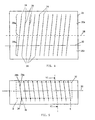
- Fig. 1a and 1b show two identical film members with printed wiring applied thereto in order to form a winding.
- Fig. 2 is a diagrammatic view of an HF antenna formed using the film members illustrated in Figures 1a and 1b with the inserted magnetic core in accordance with the invention.
- Fig. 3 shows a cross-section on a larger scale taken on the line III-III of Figure 2.
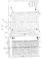
- Figure 4 shows a film with applied printed wiring in order to form one complete layer of winding.
- Figure 5 shows an HF antenna formed using the film in accordance with Figure 4 with an inserted magnetic core in accordance with the invention.
- Figure 6 is a cross-section on a larger scale taken on the line VI-VI of Figure 5.
- Figures 7 and 8 show cross-sections on a larger scale of the connection parts of the printed wiring in different possible designs.
- Figure 9 shows a film with printed wiring in order to form a two-layered winding.
- Figure 10 shows a second embodiment according to the invention, of yet another method of laying out the films to produce a twin-layer winding.
- Figure 11 is a cross-sectional view of an HF antenna with a two-layered winding, similar to that shown in Figure 6.
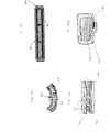
- Figure 12 shows three views of one method of forming an amorphous alloy flexible core.
- Figure 13 is a blown up cross-sectional view of several amorphous alloy strips of Figure 12, stacked, depicting the oxide layer surrounding the alloy strip and the adhesive layer which can be used to hold the strips together.
- Figure 14a is cross-sectional view of a second method of holding the amorphous alloy strips together.
- Figures 14b-14d are two dimensional views of Figure 14a showing different configurations of the foil 136.
- Figure 15 is a cross-sectional view of yet another mehtod of holding the amorphous strips together.
- Figure 16a is a cross-sectional view of the flexible core of an antenna formed of blocks of amorphous alloy.
- Figure 16b is the same core of Figure 16a bent.
- Figure 17 is a cross-sectional view of a possible resultant flexible antenna configuration.
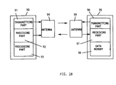
- Figure 18 is a diagrammatic representation of a transponder system in which the HF antenna in accordance with the invention may be used.
- a first embodiment of the HF antenna to be described herein comprises a winding which is composed of two identical film parts 10a and 10b as illustrated in Figures 1a and 1b. On one surface of the film parts 10a and 10b, printed wiring 12a and 12b is applied. The production of the said printed wiring 12a and 12b on the film members 10a and 10b may take place using state of the art printed circuit board manufacturing methods.
- the printed wiring 12a and 12b is arranged at such an angle to the longitudinal axis 14 of a magnetic core 16, which is to be employed together with the film parts 10a and 10b as shown in Figure 2, such that the end points 18a and 18b on the one edge of the film members 10a and 10b from the starting points 20a and 20b, placed on the other edge of the film parts 10a and 10b, of the printed wiring 12a and 12b, are offset by half the distance between the sections of printed wiring 12a and 12b as measured along the longitudinal axis 14 of the magnetic core 16.
- the distance of the end points 18a is indicated as d and furthermore the offset by d/2 will be seen.
- the magnetic core 16 consists of thin flexible layers of amorphous metallic glass as will be explained below.
- the printed wiring 12a on the film member 10a forms half a winding layer of the complete winding layer surrounding magnetic core 16 in the finished HF antenna.
- the second half of the winding layer is constituted by the printed wiring 12b on the film member 10b.
- the film parts 10a and 10b have respective elongated windows 22a, 22b, and respectively, 24a and 24b formed in them adjacent to the starting points 20a and 20b and the end points 18 and 18b, such windows being spanned by the printed wiring 12a and 12b.
- these windows are necessary in order to connect the printed wiring sections together and hence to complete the winding layer surrounding the magnetic core 16.
- the printed wiring 12a and 12b in the Figures 1a and 1b is applied to the surface of the film parts 10a and 10b which is turned away from the reader.
- the magnetic core 16 is so positioned on the film part 10a that it assumes the position illustrated in Figure 2.
- the printed wiring 12a is on the surface of the film part 10a which is facing away from the magnetic core 16.
- the film part 10b is so positioned on the magnetic core 16 that the printed wiring 12b is on the surface, which is facing away from the magnetic core 16, of the film part 10b; this arrangement is to be seen in Figure 2.
- the windows 22b and 24a and furthermore 22a and 24b are arranged over each other, and the parts of the printed wiring respectively spanning these windows are directly opposite to each other without there being any film material between them.
- the starting and end points of the directly opposite printed wiring may be connected together by various different methods so that after connection a complete winding layer extends around the magnetic core 16, which runs from the starting point A as far as the end point E. It is to be noted that the distances between the individual windings are of course substantially smaller in practice than in the figures so that a large number of turns may be wound around the magnetic core 16.
- FIG 4 shows a film 26, which consists of two integrally joined film parts 26a and 26b.
- the surface turned away from the reader of the film 26 bears printed wiring 28, which constitutes a complete winding layer.
- the printed wiring 28 consisting of connected printed wiring sections 28a and 28b, which in this case run at such an angle to the longitudinal axis 20 of the magnetic core 32 illustrated in Figure 5 that the end points 34 of the printed wiring sections 28a assume a position exactly over the starting point 36 of the printed wiring sections 28b, when the film 26 is bent along the line 38 through 180°.
- the end points 34 are offset by the full spacing (as measured in the direction of the longitudinal axis 30 of the magnetic core 32) between the printed wiring 28 (as measured in the direction of the longitudinal axis 30 of the magnetic core 32) in relation to the starting points 36.
- the magnetic core 32 is so positioned on the film 26 that its longitudinal axis 30 assumes the position shown in broken lines in Figure 4, whereafter the film 26 is bent around the line 38 through 180°, so that it surrounds the magnetic core 32 like a loop. Owing to the oblique setting of the printed wiring the end points 34 are exactly over the starting points 36 so that the same are able to be electrically connected with each other.
- the printed wiring 28 then constitutes a complete winding layer surrounding the magnetic core 32, such layer extending from the starting point A to the end point E.
- connection area As shown in Figure 7, which is a cross-sectional view of the connection area, a specific method of connection may be utilized if the film material is polyimide.
- a particular feature of the HF antenna made using this film in this connection method is that the printed wiring 40 is positioned on the surface, that is facing the magnetic core 42, of the polyimide film 44.
- windows as disclosed in Figures 1 and 2, would be required.
- projections 46 and 48 are produced at these positions when the printed wiring is produced.
- an adhesive layer 50 is provided on the printed wiring side of the film 44, which in addition to the insulating effect also ensures adhesion of the film to the magnetic core 42.
- the adhesive layer 50 originally also extended over the projections 46 and 48 of the printed wiring, but however, for the production of the connections at the start and end points, pressure is applied in these zones on the film so that the projections 46 and 48 pierce the adhesive layer 50 and come into contact with each other. Owing to the use of the adhesive layer 50, the electrically conducting connection produced persists even when no pressure is applied to the connecting zones.
- Figure 8 shows, on a larger scale, a cross-section of the connecting region of the printed wiring 54 and 56 of film 52, in order to indicate another way of producing the electrical connection for the printed wiring 54 and 56.
- the film 52 consists of polyimide as in the working embodiment of Figure 7, and the printed wiring 54 and 56 is positioned on the surface that faces the magnetic core 58, of the film 52.
- an adhesive layer 60 is utilized in order to provide electrical insulation between the printed wiring 54 and 56 and the magnetic core 58.
- openings are formed in the adhesive layer 60 and in the openings the exposed printed wiring material is tinned.
- heat and pressure are applied through the polyimide film to the connecting zone so that a soldered joint 62 is produced between the sections 54 and 56 of the printed wiring.
- a film 64 bears a printed wiring section 66 in order to constitute a first winding layer and printed wiring section 68 to form a second one.
- the magnetic core 70 is so positioned on the section 72 of the film 64 as is illustrated in broken lines in Figure 9.
- the film section 74 is then folded along the line 76 through 180° onto the magnetic core 70.
- the mutually opposite start and end points of the printed wiring 66 are electrically connected with each other using one of the above described methods.
- the film 64 with the film sections 78 and 80 is folded to the left (in terms of Figure 9) through 180° along the line 82 so that the film section 78 takes up a position over the film section 72 and the magnetic core 70.
- the film section 80 is so folded along the line 84 through 180° that it is underneath the film section 74 and the magnetic core 70.
- the start and end points, which in this condition are superposed, of the printed wiring 68 are electrically connected with each other using one of the above methods.
- the lowermost section of the printed wiring 66 is connected with the lowermost section of the printed wiring 68 directly on the film so that after the described folding or bending and connecting operations a continuous winding extends through the first winding layer with the printed wiring 66 and the second winding layer extends with the printed wiring 68 from the start point A to the end point E.
- a second method of forming a multi-layer winding is shown in Figure 10 .
- Two films 100 and 102 are shown bearing printed wiring sections 106 and 104 respectively. It will be noted, that the first and the last printed wires extend beyond the rest of the printed wiring section 104 , to form extensions 108 and 126 .
- the film 102 will be the inside film and the film 100 will be the outside film. The surface turned away from the reader of both films 100 and 102 bears printed wiring 106 and 104 .
- the magnetic core 70 is positioned underneath section 110 of the film 104 as is illustrated in Figure 10 by the dashed lines in film 102 .
- the film section 112 is then folded back into the page along the center line 114 through 180°, sliding underneath the magnetic core 70 such that the magnetic core 70 is lying between the film sections 110 and 112 .
- the mutually opposite start and end points of the printed wiring 102 are electrically connected with each other using one of the above described methods.
- the folded film 102 is layed upon the printed wire section 122 of film 100 , such that printed wiring section 112 of film 102 is lying directly over printed wiring section 122 of film 100 . Therefore, the center lines 114 and 118 coincide and the folded film 102 connection points a2 are lined up with the start points a1 of printed wiring section 122 .
- the folded film 102 when film 100 is folded along the center line 118 towards the reader, through 180°, the folded film 102 also folds through 180° such that the mutually opposite start and end points of the printed wiring 106 are electrically connected with each other and extension 108 will simultaneously be connected to the start point 124 of printed film 106 .
- printed wiring 104 and printed wiring 106 are connected to form one continuous coil. As can be seen from Figure 10 , the necessary number of coil layers can be easily facilitated.
- Figure 11 shows an HF antenna with a twin-layer winding in a cross-sectional view similar to that of Figures 3 and 6. As shown in Figure 11, it would be readily possible to produce a triple-layer winding by the addition of a further layer. The film 64 would then have to have two further film sections, which would be provided with corresponding printed wiring and connections.
- Figure 11 indicates the particular feature that the magnetic core is not, as in the previous embodiments, made up of thin layers of amorphous metallic glass, but rather of individual plates 86 of ferromagnetic material, which are embedded in a base or carrier material so that the magnetic core still has the desired flexibility like a flexible chain.
- Figure 12 shows an alternative method of forming the magnetic core still using individual plates of insulated ferromagnetic material or amorphous alloy 130 .
- the insulation could be, for example, an oxide layer coating the strips.
- a stack of insulated strips of amorphous alloy 130 is formed wherein the strips are, for example, 50mm long, 20 ⁇ m thick and 12mm wide, such that the stack is still 50 mm long and 12mm wide but greater than 20 ⁇ m thick.
- this resultant core displays a rather low Q performance. If, however, the width of the strip 130 is cut from 12mm to 2 or 3mm, thereby yielding a stack 50mm long, 3 mm wide and for example .6mm thick, the Q performance of the core is enhanced greatly. Furthermore, the more narrow the strips, the higher the Q performance.
- FIG. 13 There are many different ways to connect these stacks or blocks of amorphous alloy such that they are attached to one another while still maintaining flexibility of movement.
- One method shown in Figure 13 is to adhere the layer of strips together by using a tacky adhesive layer 134 between the strips.
- the adhesive would fill in the surface roughness that may exist on the surface of the strips.
- a very thin layer of adhesive can be achieved by spraying, rolling or dipping the strips into a bath.
- Adhesive is also available in a tape version.
- the adhesive can be applied judiciously such that flexibility of movement is not restricted.
- the adhesive can be cured in many ways including heat, pressure, ultra-violet source, and light source. The amount of time required for curing would depend upon the type of adhesive.
- a second method of forming a stacked amorphous core is to stack, for example, 30 layers of 50mm long, 3 mm wide and 20 ⁇ m thick strips of amorphous alloy 130 on top of one another, and then wrap an adhesive coated piece of foil 136 around the stack such that the adhesive is contacting the top and bottom strip as well as the edges of all the strips as shown in Figure 14a .
- the foil 136 can be wrapped around the block of strips 130 , either along the full length as shown in Figure 14b , in two strips on either end like a clamp as shown in Figure 14c , or one strip in the middle to facilitate flexibility on the ends as shown in Figure 14d .
- a third method of forming a stacked amorphous core is to again stack 30 layers of 50mm long, 3mm wide and 20 ⁇ m thick strips of amorphous alloy on top of one another, and then wrap a non-coated foil 138 around the stack such that one end of the foil covers the other end as shown in Figure 15 .
- laminate the region of overlap of the foil 140 by applying heat or pressure and/or use an adhesive to adhere the overlapping foil to itself.
- the foil 138 can be wrapped around the blocks or single strips either along the full length, in two strips on either end like a clamp, or one strip in the middle to facilitate flexibility on the ends.
- a method for forming an antenna from several blocks of strips or several single strips is shown in Figure 16 .
- the blocks or single strips of amorphous alloy 130 are placed beside one another, leaving space in between for isolation and orientation purposes, on an adhesive coated foil 136 in Figure 16a .
- the antenna core can be bent to any desired radius or shape as shown in figure 16b .
- a second adhesive foil 136 can then be adhered to the topside of the blocks or single strips 130 , maintaining the antenna core in the desired shape.
- the adhesive tape may be one piece that just gets wrapped around the blocks or single strips, either along the full length of the blocks or single strips, in two strips on either end like a clamp, or one strip in the middle to facilitate flexibility on the ends.
- double sided-adhesive tape one layer of blocks or single strips can be mounted on both sides of the tape.
- the above described HF antenna may be advantageously employed in a transponder system as in the illustrated working embodiment of the diagrammatic Figure 18.
- This transponder system comprises an interrogating device 90 with a transmitting part 91, a receiving part 92 and a processing part 93.
- the transmitting part 91 and the receiving part 92 are coupled with an antenna 94, which is able to transmit and receive HF signals.
- the transponder system comprises an answering device 95 with a transmitting part 96, a receiving part 97 and a data memory 98.
- the transmitting part 96 and the receiving part 97 are coupled with an antenna 99 which is able to transmit and receive the HF signals.
- the answering device 95 may be arranged on some object which is denoted by an identification number and this identification number is stored in the data memory 98.
- the content of the data memory 98 may be transmitted to the interrogating device 90 and it may be process by the processing part 93. It is in this manner that it is possible to identify the object which bears the answering device 95.
- the complete answering device may be housed in a synthetic resin card or board, which for instance is in the form of a credit card. In the case of this application, it is necessary for the antenna 99 together with its antenna winding to be very thin and furthermore so flexible that when the synthetic resin card is bent, in which it is accommodated, it is not damaged.
- the interrogating device 90 transmits continuously or only after actuating a push button, not shown, an HF interrogating pulse (which is produced in the transmitting part 91) via the antenna 94.
- the frequency of the HF pulse will for instance be at approximately 130 kHz.
- the emitted HF interrogating pulse is received by the antenna 99 of the answering device 95.
- the HF interrogating pulse received by the antenna 99 is rectified in the receiving part 97 and used to charge a capacitor functioning as an energy storing means and from which the power supply energy for the answering device 95 is taken after the end of the HF interrogating pulse.
- the answering device 95 When the voltage present in the energy storing capacitor has a sufficient value after the end of the HF interrogating pulse, in the answering device 95 the transmission of a HF signal via the antenna 99 is caused to take place and from the transmitting part 96, such signal containing the content of the data memory 26 in an encoded form.
- This encoding action may for instance be by modulation of the HF signal.
- the HF signal which is transmitted from the antenna 99, is received by the antenna 94 of the interrogating device 90 and it is fed from the receiving part 91 thereof to the processing part 93, in which the HF signal is then decoded.
- the interrogating device 90 it is possible to use the interrogating device 90 to read the content of the data memory 98 so that with reference to the decoded information it is possible to positively identify the object, on which the answering device 95 is arranged or to identify a person carrying the answering device 95.
- the detailed design of the interrogating device 90 and of the answering device 95 is only of subordinate importance for the HF antenna described herein and may be as is described in the European patent publication 0 301 127 A.
- HF antenna described herein is particularly suitable for application in an answering device in the form of synthetic resin card owing to its thin and flexible structure.
- a piece of film polyester with a thickness of 12 to 50 microns is employed, on which the printed wiring of copper is applied with a thickness of 35 microns. Adjacent to the start and end points of the printed wiring windows are formed as shown in Figure 1, over which the printed wiring is spanned. The width of the printed wiring is equal to 100 microns and furthermore, the distance from one piece of printed wiring to the next is equal to 100 microns.
- thin layers of amorphous metallic glass are used as, for instance, as described in A.I.P. Cosf. Vol. 24, 1974, pages 745 and 746, "Ferromagnetic Behavior of Metallic Glasses" by Sherwood, R. C., et al.
- a material which may be utilized for the layers of the magnetic core is as described in the paper "Weichmagnetician Kristalline und Amorphe Metale” by Boll, R. and Hilzinger, H. R., in “Elektronik”, 1987.
- the connection of the start and end points, which are exposed in the window zones, is performed by welding or soldering.
- the printed wiring is on the surface of the polyester film which is turned away from the magnetic core.
- Example 2 The same materials are employed for the film, the printed wiring and the magnetic core as in Example 1. At the start and end points of the printed wiring, no windows are formed in the film however.
- the film with the printed wiring is so wrapped around the magnetic core that the printed wiring is on the side of the film facing away form the magnetic core.
- the production of the electrically conducting connections between the start and end points of the printed wiring is performed by a welding process in which two dies are employed on the two sides to apply pressure and heat in the connection zone so that the polyester film present in the connection zone is heated and displaced by pressure.
- the same materials are utilized for the film, the printed wiring and the magnetic core as in the working embodiment 1.
- the printed wiring is however coated with an adhesive and the film is so wrapped around the magnetic core that the film is on the outside and the adhesive comes into contact with the magnetic core and also holds the connection zones together. Adjacent to the start and end points of the printed wiring section projections are formed, which are joined together by pressure until an electrical contact is formed. The adhesive maintains the electrical connection.
- a 12 micron thick polyimide film is used, on which the copper printed wiring is applied with a thickness of 18 or 35 microns.
- the copper material is tinned with a thickness of 4 to 5 microns and furthermore the breadth and the distance apart between the sections of printed wiring amounts to 100 microns.
- For the magnetic core the same material is utilized as in Example 1.
- an adhesive layer and the film with the printed wiring and the adhesive layer is so wrapped around the magnetic core that the adhesive becomes united with the magnetic core. Adjacent to the start and end points of the printed wiring, heat is transmitted to the printed wiring through the polyimide film so that the tinned printed wiring is soldered together at a joint.
- the magnetic core is made up of individual plates of ferromagnetic material and not of individual layers of amorphous metallic glass, such individual plates being connected with the aid of a carrier or base material to take the form of a chain.
- any flexible core will work with the described embodiments above.
Landscapes
- Details Of Aerials (AREA)
Claims (10)
- Procédé de production d'une antenne HF comprenant un noyau magnétique (16) en forme de feuille, souple et à éléments multiples, qui est entouré par un bobinage d'antenne constitué d'une pluralité de spires, et comportant les étapes suivantes :a) un câblage imprimé (12a et 12b) est formé sur un film souple (10a et 10b) de polyester qui consiste en deux parties séparées (10a et 10b), de telle sorte que le câblage imprimé (12a et 12b) est disposé sur chaque partie du film (10a et 10b) afin de constituer une moitié de couche de bobinage et de telle sorte que sur chaque partie de film (10a et 10b), le câblage imprimé (12a et 12b) s'étend en parallèle, à une même distance de séparation et suivant un angle avec l'axe longitudinal (14) du noyau magnétique (16) tel que les points de fin (18a et 18b) sur un bord d'une partie de film (10a et 10b), du câblage imprimé (12a et 12b), sont décalés par rapport aux points de début (20a et 20b) sur l'autre bord d'une partie de film (10a et 10b) de la moitié de la distance entre les sections du câblage imprimé (12a et 12b), mesurée dans la direction longitudinale du noyau magnétique,b) dans le film (10a et 10b), dans une position adjacente aux points de début et de fin (20a, 20b, 18a et 18b) du câblage imprimé (12a et 12b), des fenêtres (22a, 22b, 24a et 24b) sont produites, dans lesquelles le câblage imprimé (12a et 12b) est exposé dans une position adjacente aux points de début et de fin (20a, 20b, 18a et 18b),c) le noyau magnétique (16) est disposé sur la face d'une partie de film (10b) qui est tournée à l'opposé du câblage imprimé, de telle sorte que l'axe longitudinal (14) du noyau magnétique (16) est sur la ligne centrale qui partage en deux la longueur du câblage imprimé de la première partie de film,d) l'autre partie (10b) de film est disposée sur l'autre face du noyau magnétique ; les parties (10a et 10b) de film sont agencées l'une par rapport à l'autre de telle sorte que les points de début et de fin (20a, 20b, 18a et 18b) exposés dans les fenêtres (22a, 22b, 24a et 24b) des parties de film (10a et 10b) du câblage imprimé (12a et 12b), sont superposés,e) les points superposés de début et de fin (20a, 20b, 18a et 18b) sont reliés les uns aux autres électriquement, de telle sorte que les moitiés de couches de bobinage sont reliées sous la forme d'une couche de bobinage entière entourant le noyau magnétique (16).
- Procédé selon la revendication 1, caractérisé en ce que la connexion conductrice électriquement du câblage imprimé (12a et 12b) est produite par soudage.
- Procédé selon la revendication 1, caractérisé par les étapes suivantes :a) le câblage imprimé (12a et 12b) est étamé dans une position adjacente aux points de début et de fin (20a, 20b, 18a et 18b) exposés dans les fenêtres (22a, 22b, 24a et 24b),b) les points de début et de fin étamés (22a, 22b, 24a et 24b) qui, après la disposition de la partie de film (10a et 10b) sur les deux faces du noyau magnétique, sont superposés, du câblage imprimé (12a et 12b), sont reliés les uns aux autres par soudage.
- Procédé de production d'une antenne HF comprenant un noyau magnétique (32) en forme de feuille, souple et à éléments multiples, qui est entouré par un bobinage d'antenne constitué d'une pluralité de spires, et comportant les étapes suivantes :a) un câblage imprimé (28) est formé sur un film souple (26) de polyester qui consiste en deux parties (26a et 26b), qui sont intégrées l'une à l'autre de telle sorte que des sections (28a) du câblage imprimé s'étendant parallèlement les unes aux autres et avec un espacement constant entre elles sur une partie (26a) de film sont reliées par contact électrique à des sections (28b) de câblage imprimé qui s'étendent parallèlement les unes aux autres et avec un espacement constant sur l'autre partie (26b) de film pour former respectivement une section continue (28) de câblage imprimé, les sections (28) de câblage imprimé sur le film (36) s'étendant suivant un angle avec l'axe longitudinal (30) du noyau magnétique (32) tel que les points de fin (34) au niveau d'un bord du film (26), du câblage imprimé (28), sont décalés par rapport aux points de début (36), placés sur l'autre bord du film (26), de la distance complète entre les sections (28) de câblage imprimé, mesurée le long de l'axe longitudinal (30) du noyau magnétique (32),b) le noyau magnétique (32) est disposé sur la face du film (26) opposée au câblage imprimé (38) de telle sorte qu'un bord longitudinal du noyau magnétique (32) est sur la ligne qui partage en deux la longueur du câblage imprimé,c) le film (26) avec le câblage imprimé (28) est replié de 180° autour de la ligne centrale (38) de telle sorte qu'il entoure le noyau magnétique (32),d) les points de début et de fin (36 et 34) du câblage imprimé (12a et 12b) qui, après un tel pliage, sont superposés, sont soudés en utilisant des étampes à façonnage à chaud et une application de pression, ce qui conduit à un déplacement par compression du matériau de polyester portant le câblage imprimé (29) dans une position adjacente aux connexions à produire.
- Procédé de production d'une antenne HF comprenant un noyau magnétique (42) en forme de feuille, souple et à éléments multiples qui est entouré par un bobinage d'antenne constitué d'une pluralité de spires, et comportant les étapes suivantes :a) le câblage imprimé (40 et 41) est formé sur un film souple (44) de polyester conformément à l'étape a) de la revendication 4 et des saillies (46 et 48) sont produites aux points de début et de fin du câblage imprimé (40 et 41),b) dans une position adjacente aux points de début et de fin du câblage imprimé (40 et 41), la surface qui porte le câblage imprimé (40 et 41) du film (44) comporte une couche (50) d'un adhésif isolant appliquée sur celle-ci,c) le noyau magnétique (42) est disposé sur la face du film (44) portant le câblage imprimé (40 et 41) de telle sorte qu'un bord longitudinal du noyau magnétique (42) est approximativement sur la ligne de partage en deux de la longueur du câblage imprimé,d) le film (44) avec le câblage imprimé (40 et 41) est replié de 180° autour de la ligne centrale, de telle sorte qu'il est entraíné autour du noyau magnétique (42),e) les saillies (46 et 48) qui, après un tel pliage du film (44), sont superposées aux points de début et de fin du câblage imprimé (40 et 41), sont comprimées ensemble au niveau de la zone recouverte par un adhésif jusqu'à ce qu'il y ait un contact électrique entre elles.
- Procédé de production d'une antenne HF comprenant un noyau magnétique (58) en forme de feuille, souple et à éléments multiples constitué d'une pluralité de spires, et comportant les étapes suivantes :a) le câblage imprimé (54 et 56) est formé conformément à l'étape a) de la revendication 4 sur un film souple (52) de polyimide, la soudage se faisant en ses points de début et de fin,b) la surface du film portant le câblage imprimé (54 et 56) est pourvue d'une couche isolante (60) d'un adhésif,c) le noyau magnétique est disposé sur la surface du film (52) recouverte de l'adhésif, de telle sorte qu'un bord longitudinal du noyau magnétique est approximativement sur la ligne de partage en deux de la longueur du câblage imprimé,d) le film (52) avec le câblage imprimé (54 et 56) est replié de 180° autour de la ligne centrale de telle sorte qu'il entoure le noyau magnétique (58),e) les points de début et de fin du câblage imprimé (54 et 56) qui, après un tel pliage, sont superposés, sont connectés ensemble par soudage par une transmission de chaleur par l'intermédiaire du film (52), sur les points de début et de fin.
- Procédé selon l'une quelconque des revendications précédentes, caractérisé en ce qu'une pluralité de parties (10a, 10b ; 26a et 26b) de film, constituant chacune une couche de bobinage, est disposée autour du noyau magnétique (16 et 32) et en ce que, afin de former un bobinage à couches multiples, la fin du bobinage d'une couche est connectée respectivement avec le début du bobinage de la couche suivante de bobinage.
- Procédé selon l'une quelconque des revendications précédentes 1 à 7, caractérisé en ce que le noyau magnétique en forme de feuille, souple et à éléments multiples, est fabriqué en un matériau ferromagnétique.
- Procédé selon la revendication 8, caractérisé en ce que le noyau magnétique (16 32; 42 ; 58 et 70) est composé de couches minces de verre métallique amorphe.
- Procédé selon la revendication 9, caractérisé en ce que le noyau magnétique est composé de plaques de ferrite alignées et assemblées (86), qui sont maintenues ensemble par un film souple porteur.
Priority Applications (4)
| Application Number | Priority Date | Filing Date | Title |
|---|---|---|---|
| DE1992626348 DE69226348T2 (de) | 1992-02-05 | 1992-02-05 | Verfahren zur Herstellung einer flexibelen HF-Antenne |
| EP92101918A EP0554486B1 (fr) | 1992-02-05 | 1992-02-05 | Procédé pour la fabrication d'une antenne haute fréquence flexible |
| JP5018976A JPH06216628A (ja) | 1992-02-05 | 1993-02-05 | アンテナおよびその製造方法 |
| US08/239,261 US5396698A (en) | 1992-02-05 | 1994-05-06 | Manufacture of a flexible antenna |
Applications Claiming Priority (2)
| Application Number | Priority Date | Filing Date | Title |
|---|---|---|---|
| EP92101918A EP0554486B1 (fr) | 1992-02-05 | 1992-02-05 | Procédé pour la fabrication d'une antenne haute fréquence flexible |
| US08/239,261 US5396698A (en) | 1992-02-05 | 1994-05-06 | Manufacture of a flexible antenna |
Publications (2)
| Publication Number | Publication Date |
|---|---|
| EP0554486A1 EP0554486A1 (fr) | 1993-08-11 |
| EP0554486B1 true EP0554486B1 (fr) | 1998-07-22 |
Family
ID=26130793
Family Applications (1)
| Application Number | Title | Priority Date | Filing Date |
|---|---|---|---|
| EP92101918A Expired - Lifetime EP0554486B1 (fr) | 1992-02-05 | 1992-02-05 | Procédé pour la fabrication d'une antenne haute fréquence flexible |
Country Status (3)
| Country | Link |
|---|---|
| US (1) | US5396698A (fr) |
| EP (1) | EP0554486B1 (fr) |
| JP (1) | JPH06216628A (fr) |
Cited By (1)
| Publication number | Priority date | Publication date | Assignee | Title |
|---|---|---|---|---|
| WO2004030148A1 (fr) * | 2002-09-30 | 2004-04-08 | The Furukawa Electric Co., Ltd. | Etiquette rfid et son procede de production |
Families Citing this family (34)
| Publication number | Priority date | Publication date | Assignee | Title |
|---|---|---|---|---|
| US5485170A (en) * | 1993-05-10 | 1996-01-16 | Amsc Subsidiary Corporation | MSAT mast antenna with reduced frequency scanning |
| WO1995027928A1 (fr) * | 1994-04-08 | 1995-10-19 | Citizen Watch Co., Ltd. | Antenne pour appareil electronique portable |
| US5521609A (en) * | 1995-01-13 | 1996-05-28 | The United States Of America As Represented By The Administrator Of The National Aeronautics And Space Administration | Magnetic antenna using metallic glass |
| CH686696B5 (fr) * | 1995-03-07 | 2000-09-15 | Isa France Sa | Montre munie d'une antenne,notamment du type montre-bracelet. |
| US5764197A (en) * | 1995-06-20 | 1998-06-09 | Murata Manufacturing Co., Ltd. | Chip antenna |
| KR100459839B1 (ko) * | 1995-08-22 | 2005-02-07 | 미쓰비시 마테리알 가부시키가이샤 | 트랜스폰더용안테나및트랜스폰더 |
| US5917791A (en) | 1995-11-30 | 1999-06-29 | Sanyo Electric Co., Ltd. | Apparatus for discriminating optical recording media of different thicknesses from each other and reproducing information therefrom |
| JP3147756B2 (ja) * | 1995-12-08 | 2001-03-19 | 株式会社村田製作所 | チップアンテナ |
| JPH09275316A (ja) * | 1996-04-05 | 1997-10-21 | Murata Mfg Co Ltd | チップアンテナ |
| JP2003045731A (ja) * | 2001-07-30 | 2003-02-14 | Nec Tokin Corp | 非接触電力伝送装置 |
| US7978078B2 (en) | 2001-12-21 | 2011-07-12 | Sensormatic Electronics, LLC | Magnetic core transceiver for electronic article surveillance marker detection |
| JP2003283231A (ja) * | 2002-03-26 | 2003-10-03 | Aisin Seiki Co Ltd | アンテナおよびその製造方法 |
| JP2003318633A (ja) * | 2002-04-25 | 2003-11-07 | Mitsubishi Materials Corp | リーダライタ装置、リーダ装置又はライタ装置用アンテナコイル及びその製造方法 |
| DE10302646B4 (de) * | 2003-01-23 | 2010-05-20 | Vacuumschmelze Gmbh & Co. Kg | Antennenkern und Verfahren zum Herstellen eines Antennenkerns |
| US7167140B2 (en) * | 2003-07-02 | 2007-01-23 | Nec Tokin Corporation | Coil antenna |
| JP4152845B2 (ja) * | 2003-09-22 | 2008-09-17 | 株式会社アルファ | アンテナ装置および該アンテナ装置を装着した自動車のドアアウトサイドハンドル装置 |
| JP4619953B2 (ja) * | 2003-10-23 | 2011-01-26 | 株式会社東芝 | インダクタンス素子 |
| US7795863B2 (en) * | 2004-02-23 | 2010-09-14 | Iowa State University Research Foundation, Inc. | Method and apparatus for forming coil for use in eddy current sensing probe |
| FR2884650B1 (fr) * | 2005-04-18 | 2007-10-12 | Valeo Electronique Sys Liaison | Antenne |
| DE102005026410B4 (de) * | 2005-06-08 | 2007-06-21 | Vacuumschmelze Gmbh & Co. Kg | Anordnung mit einem induktiven Bauelement |
| JP2007041666A (ja) * | 2005-08-01 | 2007-02-15 | Ricoh Co Ltd | Rfidタグ及びその製造方法 |
| JP4974621B2 (ja) * | 2005-09-15 | 2012-07-11 | 株式会社半導体エネルギー研究所 | 半導体装置及びその作製方法 |
| DE102005050204A1 (de) * | 2005-10-20 | 2007-04-26 | Eads Deutschland Gmbh | Verfahren zur Herstellung einer strukturintegrierten Antenne |
| JP2008042387A (ja) * | 2006-08-03 | 2008-02-21 | Aisin Seiki Co Ltd | アンテナ用磁心 |
| EP2051329A4 (fr) * | 2006-08-09 | 2010-11-03 | Murata Manufacturing Co | Bobine d'antenne et dispositif d'antenne |
| TW200826366A (en) * | 2006-11-02 | 2008-06-16 | Murata Manufacturing Co | Antenna coil and antenna unit |
| DE202007001542U1 (de) * | 2007-02-02 | 2008-06-19 | Neosid Pemetzrieder Gmbh & Co. Kg | Induktives Bauelement, insbesondere Antenne |
| TWM390532U (en) * | 2010-05-19 | 2010-10-11 | Advanced Connection Technology Inc | Iron core coil assembly |
| CN102544730A (zh) * | 2011-12-27 | 2012-07-04 | 深圳市江波龙电子有限公司 | 一种磁芯天线、sim卡及移动通信终端 |
| JP5713148B2 (ja) * | 2013-01-24 | 2015-05-07 | 株式会社村田製作所 | 磁性体コア内蔵樹脂多層基板の製造方法 |
| AT514661A1 (de) * | 2013-07-25 | 2015-02-15 | Seibersdorf Labor Gmbh | Behälter |
| CN105789837A (zh) * | 2014-12-26 | 2016-07-20 | 环旭电子股份有限公司 | 用于无线通信的天线 |
| SK289113B6 (sk) * | 2016-09-19 | 2023-09-13 | Logomotion, S.R.O | Anténa sjadrom, najmä miniatúrna RFID a/alebo NFC anténa, a spôsob jej výroby |
| KR20190009936A (ko) * | 2017-07-20 | 2019-01-30 | 삼성전기주식회사 | 안테나 모듈 및 이를 구비하는 전자 기기 |
Family Cites Families (7)
| Publication number | Priority date | Publication date | Assignee | Title |
|---|---|---|---|---|
| DE348636C (de) * | 1920-07-30 | 1922-02-13 | Adolph Lionel Burlin | Verfahren zur Herstellung von Papierzeug aus frisch gestochenem Torf |
| JPS54154245A (en) * | 1978-05-26 | 1979-12-05 | Matsushita Electric Ind Co Ltd | Ferrite antenna |
| JPS56150807A (en) * | 1980-04-22 | 1981-11-21 | Tdk Corp | Coil device |
| US4814782A (en) * | 1986-12-11 | 1989-03-21 | Motorola, Inc. | Single turn ferrite rod antenna and method |
| US4862184A (en) * | 1987-02-06 | 1989-08-29 | George Ploussios | Method and construction of helical antenna |
| DE8815967U1 (de) * | 1988-05-27 | 1989-09-21 | Junghans Uhren GmbH, 7230 Schramberg | Antenne für eine kleine Funkuhr |
| FR2640822B1 (fr) * | 1988-12-21 | 1991-03-29 | Aerospatiale | Reflecteur d'ondes electromagnetiques pour antenne et son procede de fabrication |
-
1992
- 1992-02-05 EP EP92101918A patent/EP0554486B1/fr not_active Expired - Lifetime
-
1993
- 1993-02-05 JP JP5018976A patent/JPH06216628A/ja active Pending
-
1994
- 1994-05-06 US US08/239,261 patent/US5396698A/en not_active Expired - Lifetime
Cited By (2)
| Publication number | Priority date | Publication date | Assignee | Title |
|---|---|---|---|---|
| WO2004030148A1 (fr) * | 2002-09-30 | 2004-04-08 | The Furukawa Electric Co., Ltd. | Etiquette rfid et son procede de production |
| US7126482B2 (en) | 2002-09-30 | 2006-10-24 | The Furukawa Electric Co., Ltd. | RFID tag and its manufacturing method |
Also Published As
| Publication number | Publication date |
|---|---|
| US5396698A (en) | 1995-03-14 |
| JPH06216628A (ja) | 1994-08-05 |
| EP0554486A1 (fr) | 1993-08-11 |
Similar Documents
| Publication | Publication Date | Title |
|---|---|---|
| EP0554486B1 (fr) | Procédé pour la fabrication d'une antenne haute fréquence flexible | |
| US5638080A (en) | Manufacture of a flexible antenna, with or without an inner permeable magnetic layer | |
| US7694886B2 (en) | RFID tag and manufacturing process thereof | |
| EP1755069A1 (fr) | Mince etiquette ci et procede de fabrication de celle-ci | |
| US5867100A (en) | Air Coil a security badge and a transponder | |
| JP3956172B2 (ja) | データキャリア及びデータキャリア用アンテナ | |
| TWI267788B (en) | Radio frequency identification (RFID) tag and manufacturing method thereof | |
| US20130134227A1 (en) | Multi-Layered Flexible Printed Circuit and Method of Manufacture | |
| US5285191A (en) | LC marker construction useful as an electromagnetically interrogatable transponder means | |
| HK1000220B (en) | Electronic module with an integrated circuit for a portable object of small dimensions, such as a card or a key, and process for manufacturing such a module | |
| HK1042574A1 (en) | Contactless access ticket and method for making same | |
| HK1000220A1 (en) | Electronic module with an integrated circuit for a portable object of small dimensions, such as a card or a key, and process for manufacturing such a module | |
| RU2127933C1 (ru) | Антенная катушка (варианты) | |
| JPH11149536A (ja) | 複合icカード | |
| EP0886239B1 (fr) | Module sans fil et carte sans fil | |
| WO1998026939A1 (fr) | Dispositif semi-conducteur et son procede de fabrication | |
| KR19990076679A (ko) | 비접촉식 기술에서 사용하기 위한 칩카드의 제조방법 | |
| JP4236971B2 (ja) | 非接触型情報記録媒体の製造方法 | |
| CN1350680A (zh) | 制造无接触式卡的方法 | |
| JPH1013313A (ja) | 無線用識別シート | |
| KR20050017670A (ko) | 스마트 라벨 및, 그것의 제조 방법 | |
| JPH08227447A (ja) | 通信icカード | |
| JPH11144018A (ja) | 非接触式icカードのアンテナコイルの作製方法 | |
| JPH11115360A5 (fr) | ||
| JPH11115360A (ja) | 非接触icカード及びその製造方法 |
Legal Events
| Date | Code | Title | Description |
|---|---|---|---|
| PUAI | Public reference made under article 153(3) epc to a published international application that has entered the european phase |
Free format text: ORIGINAL CODE: 0009012 |
|
| AK | Designated contracting states |
Kind code of ref document: A1 Designated state(s): DE FR GB IT NL |
|
| 17P | Request for examination filed |
Effective date: 19931228 |
|
| 17Q | First examination report despatched |
Effective date: 19951115 |
|
| GRAG | Despatch of communication of intention to grant |
Free format text: ORIGINAL CODE: EPIDOS AGRA |
|
| GRAG | Despatch of communication of intention to grant |
Free format text: ORIGINAL CODE: EPIDOS AGRA |
|
| GRAH | Despatch of communication of intention to grant a patent |
Free format text: ORIGINAL CODE: EPIDOS IGRA |
|
| GRAH | Despatch of communication of intention to grant a patent |
Free format text: ORIGINAL CODE: EPIDOS IGRA |
|
| GRAA | (expected) grant |
Free format text: ORIGINAL CODE: 0009210 |
|
| AK | Designated contracting states |
Kind code of ref document: B1 Designated state(s): DE FR GB IT NL |
|
| PG25 | Lapsed in a contracting state [announced via postgrant information from national office to epo] |
Ref country code: IT Free format text: LAPSE BECAUSE OF FAILURE TO SUBMIT A TRANSLATION OF THE DESCRIPTION OR TO PAY THE FEE WITHIN THE PRE;WARNING: LAPSES OF ITALIAN PATENTS WITH EFFECTIVE DATE BEFORE 2007 MAY HAVE OCCURRED AT ANY TIME BEFORE 2007. THE CORRECT EFFECTIVE DATE MAY BE DIFFERENT FROM THE ONE RECORDED.SCRIBED TIME-LIMIT Effective date: 19980722 Ref country code: FR Free format text: LAPSE BECAUSE OF FAILURE TO SUBMIT A TRANSLATION OF THE DESCRIPTION OR TO PAY THE FEE WITHIN THE PRESCRIBED TIME-LIMIT Effective date: 19980722 |
|
| REF | Corresponds to: |
Ref document number: 69226348 Country of ref document: DE Date of ref document: 19980827 |
|
| EN | Fr: translation not filed | ||
| PLBE | No opposition filed within time limit |
Free format text: ORIGINAL CODE: 0009261 |
|
| STAA | Information on the status of an ep patent application or granted ep patent |
Free format text: STATUS: NO OPPOSITION FILED WITHIN TIME LIMIT |
|
| 26N | No opposition filed | ||
| REG | Reference to a national code |
Ref country code: GB Ref legal event code: IF02 |
|
| PGFP | Annual fee paid to national office [announced via postgrant information from national office to epo] |
Ref country code: GB Payment date: 20040107 Year of fee payment: 13 |
|
| PGFP | Annual fee paid to national office [announced via postgrant information from national office to epo] |
Ref country code: NL Payment date: 20040112 Year of fee payment: 13 |
|
| PGFP | Annual fee paid to national office [announced via postgrant information from national office to epo] |
Ref country code: DE Payment date: 20040227 Year of fee payment: 13 |
|
| PG25 | Lapsed in a contracting state [announced via postgrant information from national office to epo] |
Ref country code: GB Free format text: LAPSE BECAUSE OF NON-PAYMENT OF DUE FEES Effective date: 20050205 |
|
| PG25 | Lapsed in a contracting state [announced via postgrant information from national office to epo] |
Ref country code: DE Free format text: LAPSE BECAUSE OF NON-PAYMENT OF DUE FEES Effective date: 20050901 Ref country code: NL Free format text: LAPSE BECAUSE OF NON-PAYMENT OF DUE FEES Effective date: 20050901 |
|
| GBPC | Gb: european patent ceased through non-payment of renewal fee |
Effective date: 20050210 |
|
| NLV4 | Nl: lapsed or anulled due to non-payment of the annual fee |
Effective date: 20050901 |