EP0555193B1 - Beleuchtungsvorrichtung - Google Patents
Beleuchtungsvorrichtung Download PDFInfo
- Publication number
- EP0555193B1 EP0555193B1 EP93850020A EP93850020A EP0555193B1 EP 0555193 B1 EP0555193 B1 EP 0555193B1 EP 93850020 A EP93850020 A EP 93850020A EP 93850020 A EP93850020 A EP 93850020A EP 0555193 B1 EP0555193 B1 EP 0555193B1
- Authority
- EP
- European Patent Office
- Prior art keywords
- channel
- mounting units
- section
- light
- disposed
- Prior art date
- Legal status (The legal status is an assumption and is not a legal conclusion. Google has not performed a legal analysis and makes no representation as to the accuracy of the status listed.)
- Expired - Lifetime
Links
- 230000007704 transition Effects 0.000 claims abstract description 9
- 230000000694 effects Effects 0.000 claims abstract description 3
- 238000005286 illumination Methods 0.000 claims description 2
- 230000000063 preceeding effect Effects 0.000 claims 1
- 238000009434 installation Methods 0.000 description 1
- 230000010354 integration Effects 0.000 description 1
- 238000004519 manufacturing process Methods 0.000 description 1
- 238000000034 method Methods 0.000 description 1
- 230000000087 stabilizing effect Effects 0.000 description 1
Images

Classifications
-
- F—MECHANICAL ENGINEERING; LIGHTING; HEATING; WEAPONS; BLASTING
- F21—LIGHTING
- F21S—NON-PORTABLE LIGHTING DEVICES; SYSTEMS THEREOF; VEHICLE LIGHTING DEVICES SPECIALLY ADAPTED FOR VEHICLE EXTERIORS
- F21S2/00—Systems of lighting devices, not provided for in main groups F21S4/00 - F21S10/00 or F21S19/00, e.g. of modular construction
-
- E—FIXED CONSTRUCTIONS
- E04—BUILDING
- E04B—GENERAL BUILDING CONSTRUCTIONS; WALLS, e.g. PARTITIONS; ROOFS; FLOORS; CEILINGS; INSULATION OR OTHER PROTECTION OF BUILDINGS
- E04B9/00—Ceilings; Construction of ceilings, e.g. false ceilings; Ceiling construction with regard to insulation
- E04B9/006—Ceilings; Construction of ceilings, e.g. false ceilings; Ceiling construction with regard to insulation with means for hanging lighting fixtures or other appliances to the framework of the ceiling
-
- F—MECHANICAL ENGINEERING; LIGHTING; HEATING; WEAPONS; BLASTING
- F21—LIGHTING
- F21V—FUNCTIONAL FEATURES OR DETAILS OF LIGHTING DEVICES OR SYSTEMS THEREOF; STRUCTURAL COMBINATIONS OF LIGHTING DEVICES WITH OTHER ARTICLES, NOT OTHERWISE PROVIDED FOR
- F21V21/00—Supporting, suspending, or attaching arrangements for lighting devices; Hand grips
- F21V21/02—Wall, ceiling, or floor bases; Fixing pendants or arms to the bases
-
- F—MECHANICAL ENGINEERING; LIGHTING; HEATING; WEAPONS; BLASTING
- F21—LIGHTING
- F21Y—INDEXING SCHEME ASSOCIATED WITH SUBCLASSES F21K, F21L, F21S and F21V, RELATING TO THE FORM OR THE KIND OF THE LIGHT SOURCES OR OF THE COLOUR OF THE LIGHT EMITTED
- F21Y2103/00—Elongate light sources, e.g. fluorescent tubes
-
- F—MECHANICAL ENGINEERING; LIGHTING; HEATING; WEAPONS; BLASTING
- F21—LIGHTING
- F21Y—INDEXING SCHEME ASSOCIATED WITH SUBCLASSES F21K, F21L, F21S and F21V, RELATING TO THE FORM OR THE KIND OF THE LIGHT SOURCES OR OF THE COLOUR OF THE LIGHT EMITTED
- F21Y2113/00—Combination of light sources
Definitions
- the present invention relates to a device for indirect lighting in conjunction with a suspended ceiling structure which includes suspended sections as a support and panels supported thereon, the device comprising channel means disposed such that an out-of-sight or shielded, longitudinally extending channel is formed which is open in one direction for the emission of light, and in which longitudinally extending light fittings are disposed for the emission of light through the opening in said channel towards adjacent roof or wall portions to provide indirect lighting.
- the suspended ceiling structure has a transition in levels where said channel means is provided.
- prior art lighting devices of the abovementioned type have separate channel members attached to a portion of the wall some distance from the suspended ceiling which occasionally causes installation problems.
- Fittings typically fluorescent light fittings, are mounted in line in the longitudinal direction of the channel using various types of special attachments. The respective ends of the lights thus end up being separated from each other by not insubstantial distances which has been found to give rise to shadow effects and/or uneven light distribution which, in many cases, can be regarded as disturbing.
- US-A-4,569,004 discloses a device for indirect lighting in conjunction with a suspended ceiling structure.
- the device comprises a channel means having a channel with longitudinally extending light fittings and with an upwardly directed channel opening for the emission of light.
- the channel means comprises a frame structure carrying ceiling material and forms an integrated transition between two ceiling levels.
- the object of the invention is to provide an improved lighting device of the type described in the introduction whereby indirect lighting adjacent the transition between levels in a suspended ceiling can be provided in a simple and effective manner, even in light wells, and whereby the above drawbacks can be avoided. At the same time additional benefits can be attained, in the form of integration of the lighting into the suspended ceiling structure itself, increased flexibility and better capacity for variation when it comes to setting up the light distribution.
- the lighting device of the invention is essentially distinguished in that said channel means comprises a section integrated into the suspended ceiling structure and employed for connecting the component ceiling panels in the transition between levels of the suspended ceiling. Furthermore, the light fittings are disposed overlapping each other in the longitudinal direction of the channel such that their fields of illumination overlap each other. It thereby becomes possible to control and vary the overall distribution of light in a simple and effective manner, in that varying degrees of overlap between fittings, varying relative positions of the channel and fittings etc can be provided, as will be further illustrated below.
- the light fittings can be permanently mounted in the channel, it is advantageous in the practise of the invention if the light fittings are individually translatably adjustable in the longitudinal direction of the channel. It will be appreciated that the mutual positions and degree of overlap of the fittings can thus be simply adjusted or altered and at the same time the task of wiring up and connecting is facilitated in many cases. Fittings which are to sit at an end of the channel, a position which in many cases is not within easy reach for mounting work, can be simply moved on to their final position after being initially placed in the channel and wired up at a place where this can be done without obstruction or other difficulties.
- Arranging the light fittings in at least two rows parallel to the longitudinal direction of the channel has been found to be advantageous.
- the light fittings in a first row are disposed on mounting units which are secured to, or supported by, a first "side” wall (in the broad sense) or the “bottom” (in the broad sense) of the channel, while a second row of light fittings are disposed on mounting units which are secured to, or supported by a second, opposed “wall” of the channel, broadly speaking, and the channel bottom.
- a first "side” wall (in the broad sense) or the “bottom” (in the broad sense) of the channel while a second row of light fittings are disposed on mounting units which are secured to, or supported by a second, opposed “wall” of the channel, broadly speaking, and the channel bottom.
- An advantageous embodiment has mounting units of an angled strip configuration with a first part extending generally crosswise relative to the channel and a second part extending generally depthwise in the channel.
- the terminating edge portion of said second part of the mounting unit can be guided in a longitudinally extending groove adjacent the channel bottom while the terminating edge portion of said first part of the mounting unit can be secured by a securing means which, at a desired position, engages a longitudinally extending groove in the respective side wall of the channel, said second parts of the mounting units preferably bearing against each other where they overlap and preferably being guided in the same groove in the channel bottom.
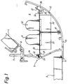
- Fig. 1 is a schematic, side view of an embodiment of a device according to the invention.
- Fig.2 is a schematic, perspective view, partly in section, of the device of Fig.1 in which certain parts have been omitted for the sake of clarity.
- Figs. 1 and 2 illustrate, by way of example, a device in accordance with the invention for the indirect suspended ceiling lighting of a transition in ceiling levels, in the form of a sloping ceiling panel 1 which forms a continuation of a lower lying horizontal ceiling panel 3.
- Panels 1 and 3 are only schematically indicated as they can be of conventional design.
- Ceiling panels 1 and 3 are supported by a section 5 which is of unitary fabrication and is integrated into the suspended ceiling structure.
- the section 5 is suspended in a conventional fashion with an inverted, capital T-shaped suspending element 7 which is only schematically indicated because it is of no significance to the invention, either.
- the section 5 Towards its bottom, the section 5 has a horizontal flange 6 for supporting the horizontal ceiling panel 3 and towards its top has a projecting receiving portion 8 for the sloping ceiling panel 1, which in the illustrated embodiment forms an angle of about 45° with the horizontal.
- the flange 6 and receiving portion 8 project outwardly in generally opposite directions.
- the section 5 defines a channel 9 having an upwardly directed opening which provides the desired release profile from the, in this case fluorescent, light fittings 11, 12, mounted in the channel 9.
- the section 5 has a generally concave configuration and can be said to have two opposed channel side walls 13, 14 and a channel bottom 15.
- Side wall 13 is essentially a freely projecting, upwardly curving section portion while side wall 14 is essentially a vertical downward continuation of the suspending element 7.
- a number of fluorescent light fittings 11, 12 are mounted in two parallel rows within the channel 9 of the section 5 in such a fashion that successive fittings lie in alternate rows and that adjacent fittings overlap each other, as illustrated in Fig. 2.
- An overlap of the order of 10 - 20 cm, typically around 15 cm has been found suitable.
- Each fitting is mounted on a separate mounting unit 21 and includes two fluorescent light holders 23, 24 secured at respective ends on the upper side of the corresponding mounting unit.
- the fluorescent lights themselves have been omitted in Fig. 2.
- other light fitting components can be mounted on the underside of the mounting unit 21.
- the mounting units 21 are similar for all the fittings, although the mounting units are opposedly arranged in either row.
- the mounting units 21 are formed from a right-angled strip having a first (in this case horizontal) plane 25 and a second (in this case vertical) plane 26.
- the holders 23, 24 are secured to the first part 25 adjacent the transition to the second part 26.
- the free edge portion 27 of the first part 25 is angled upward in the opposite direction from the second part 26 and functions as a support and securing portion as does the adjoining border portion of said first part 25.
- the portions in question are equipped with holes 29, 30 for screw fasteners 31 and 32 respectively which can be screwed securely into respective cooperating longitudinally extending grooves 33 and 35 disposed adjacent the respective side walls 14, 13 of the channel.
- the hole 29 in the upwardly angled portion 27 is used for the securing of the mounting unit 21.
- the hole 30 in said bordering region of part 25 is used for the securing of the mounting unit.
- the groove 35 runs in a projection 39 which provides a similar sort of support as the flange 37. Additional support can be provided by the cooperation of the angled up portion 27 with wall 13 directly or with a projection therefrom.
- the second parts 26 of the mounting units bear against each other where they overlap. It should be appreciated that this in itself provides a stabilizing effect. Additionally, the lower free edge regions of the second parts 26 are guided and supported in a groove 41 in the bottom part 15 of the section 5.
- the mounting units 21 can easily be given another form within the context of the selected mounting technique.
- the height of the second part 26 can be altered and thus the location of the fitting in the channel 9 will be changed.
- the mounting units 21 with fitting components mounted and electrically ready-connected can be simply placed in the channel 9 and electrically connected together, preferably in rows.
- wiring up etc is facilitated by the access to the spaces under or within the mounting units in that the fittings in their respective rows end up being separated by considerable open spaces and by the general mobility of the mounting units.
- the mounting units with fittings connected can be adjusted to the desired position and desired light distribution and securely screwed.
Landscapes
- Engineering & Computer Science (AREA)
- General Engineering & Computer Science (AREA)
- Architecture (AREA)
- Physics & Mathematics (AREA)
- Electromagnetism (AREA)
- Civil Engineering (AREA)
- Structural Engineering (AREA)
- Non-Portable Lighting Devices Or Systems Thereof (AREA)
- Vehicle Body Suspensions (AREA)
- Polarising Elements (AREA)
- Seal Device For Vehicle (AREA)
Claims (8)
- Vorrichtung zur indirekten Beleuchtung in Verbindung mit einer aufgehängten Deckenstruktur, die aufgehängte Abschnitte und Plattenmittel (1, 3) umfaßt, die hieran getragen sind, wobei die Vorrichtung Kanalmittel aufweist, die so angeordnet sind, daß ein außer Sicht liegender, sich in Längsrichtung erstreckender Kanal (9) gebildet ist, der eine nach oben gerichtete Kanalöffnung für das Emittieren von Licht aufweist und in dem sich in Längsrichtung erstreckende Licht-Ausstattungsgegenstände (11, 12) zum Emittieren von Licht durch die genannte Öffnung zur benachbarten Wand oder zu benachbarten Wandabschnitten angeordnet sind, um hierdurch für eine indirekte Beleuchtung zu sorgen, wobei die genannten Kanalmittel in die aufgehängte Dachstruktur so intregriert sind, daß ein Übergang in dem Niveau der aufgehängten Decke gebildet ist, dadurch gekennzeichnet, daß die genannten Kanalmittel einen Abschnitt (5) aufweisen, der Abschnitt so angeordnet ist, daß er ein Ende einer horizontalen Deckenplatteneinrichtung (3) an seinem Fuß abstützt und ein unteres Ende einer geneigten Deckenplatteneinrichtung (1) über Kopf abstützt, wodurch er den genannten Übergang herstellt, der Abschnitt (5) in einem Aufhängeelement (7) der aufgehängten Deckenstruktur aufgehängt ist, und daß Licht-Ausstattungsgegenstände (11, 12) einander überdeckend in Längsrichtung des Kanals (9) des Abschnitts (5) so angeordnet sind, daß die Beleuchtungsfelder aus den Licht-Ausstattungsgegenständen einander überdecken, wodurch Schattenwirkungen und/oder eine ungleichmäßige Lichtverteilung in der indirekten Beleuchtung vermieden ist.
- Vorrichtung nach Anspruch 1, dadurch gekennzeichnet, daß die Licht-Ausstattungsgegenstände (11, 12) in Längsrichtung des Kanals (9) versetzbar einstellbar sind.
- Vorrichtung nach Anspruch 1 oder 2, dadurch gekennzeichnet, daß die Licht-Ausstattungsgegenstände (11, 12) in mindestens zwei Reihen parallel zur Längsrichtung des Kanals (9) angeordnet sind.
- Vorrichtung nach Anspruch 3, dadurch gekennzeichnet, daß die Licht-Ausstattungsgegenstände (11, 12) in den jeweiligen Reihen an jeweiligen, zugeordneten Montageeinheiten (21) angeordnet sind.
- Vorrichtung nach Anspruch 4, dadurch gekennzeichnet, daß die Licht-Ausstattungsgegenstände (11) in einer ersten Reihe an Montageeinheiten (21) angeordnet sind, die von einer ersten Seitenwand (14) des Kanals und einem Kanalboden (15) festgehalten oder abgestützt sind, und daß die Licht-Ausstattungsgegenstände (12) in einer zweiten Reihe an Montageeinheiten (22) angeordnet sind, die von einer zweiten, gegenüberliegenden Seitenwand (13) des Kanals und vom Kanalboden (15) festgehalten oder abgestützt sind.
- Vorrichtung nach Anspruch 5, dadurch gekennzeichnet, daß die Montageeinheiten (22) eine Ausbildung eines abgewinkelten Streifens aufweisen, mit einem ersten Teil (25), der sich insgesamt in Querrichtung relativ zum Kanal (9) erstreckt, und einem zweiten Teil (26), der sich insgesamt in Tiefenrichtung im Kanal (9) erstreckt.
- Vorrichtung nach Anspruch 6, dadurch gekennzeichnet, daß die endenden Kantenabschnitte der zweiten Teile (26) der Montageeinheiten (22) in einer sich in Längsrichtung erstreckenden Nut (41) nahe dem Kanalboden (15) geführt sind, und daß die endenden Kantenabschnitte der genannten ersten Teile (25) der Montageeinheiten (22) über Befestigungsmittel (31 bzw. 32) befestigt sind, die sich in eine sich in Längsrichtung erstreckende Nut (33 bzw. 35) nahe der jeweiligen Seitenwand (14 bzw. 13) des Kanals erstrecken, wobei die genannten zweiten Teile (26) der Montageeinheiten bevorzugt gegeneinander dort anliegen, wo sie einander überdecken, und bevorzugt in derselben Nut (41) nahe dem Kanalboden geführt sind.
- Vorrichtung nach jedem vorangehenden Anspruch, dadurch gekennzeichnet, daß der Abschnitt (5) eine erste Kanalseitenwand (14) aufweist, die im wesentlichen eine vertikal nach unten gerichtete Fortsetzung eines Aufhängeelements (7) für den Abschnitt bildet, sowie eine zweite Kanalseitenwand (13) in Form eines im wesentlichen frei vorstehenden Abschnitts mit nach oben gekrümmtem Schnitt.
Applications Claiming Priority (2)
| Application Number | Priority Date | Filing Date | Title |
|---|---|---|---|
| SE9200292A SE505449C2 (sv) | 1992-02-03 | 1992-02-03 | Anordning för indirekt belysning i samband med en undertaksnivåövergång |
| SE9200292 | 1992-02-03 |
Publications (2)
| Publication Number | Publication Date |
|---|---|
| EP0555193A1 EP0555193A1 (de) | 1993-08-11 |
| EP0555193B1 true EP0555193B1 (de) | 1996-06-12 |
Family
ID=20385185
Family Applications (1)
| Application Number | Title | Priority Date | Filing Date |
|---|---|---|---|
| EP93850020A Expired - Lifetime EP0555193B1 (de) | 1992-02-03 | 1993-02-02 | Beleuchtungsvorrichtung |
Country Status (4)
| Country | Link |
|---|---|
| EP (1) | EP0555193B1 (de) |
| AT (1) | ATE139321T1 (de) |
| DE (1) | DE69303045T2 (de) |
| SE (1) | SE505449C2 (de) |
Cited By (4)
| Publication number | Priority date | Publication date | Assignee | Title |
|---|---|---|---|---|
| USD601006S1 (en) | 2008-09-15 | 2009-09-29 | Certainteed Corporation | Modified ceiling tile edge support clip |
| USD603692S1 (en) | 2008-09-15 | 2009-11-10 | Certainteed Corporation | Ceiling tile edge support clip |
| USD616735S1 (en) | 2009-02-19 | 2010-06-01 | Certainteed Corporation | Installation clip for a siding panel |
| USD663047S1 (en) | 2009-02-19 | 2012-07-03 | Certainteed Corporation | Siding panel having grooved ends |
Families Citing this family (1)
| Publication number | Priority date | Publication date | Assignee | Title |
|---|---|---|---|---|
| DE102016112773A1 (de) * | 2016-07-12 | 2018-01-18 | Slv Gmbh | Deckenprofil |
Family Cites Families (5)
| Publication number | Priority date | Publication date | Assignee | Title |
|---|---|---|---|---|
| US3064121A (en) * | 1958-10-16 | 1962-11-13 | Superior Electric Co | Lighting unit |
| US3202814A (en) * | 1962-07-19 | 1965-08-24 | Michael J Ceglia | Lighting device for dispelling shadows |
| US4569004A (en) * | 1984-09-17 | 1986-02-04 | Peterson William A | Cove light fixture |
| US4725931A (en) * | 1986-12-01 | 1988-02-16 | Monitronik Ltee. | Cove fixture |
| SE463977B (sv) * | 1987-09-04 | 1991-02-18 | Ecophon Ab | Undertakskonstruktion |
-
1992
- 1992-02-03 SE SE9200292A patent/SE505449C2/sv not_active IP Right Cessation
-
1993
- 1993-02-02 EP EP93850020A patent/EP0555193B1/de not_active Expired - Lifetime
- 1993-02-02 DE DE69303045T patent/DE69303045T2/de not_active Expired - Fee Related
- 1993-02-02 AT AT93850020T patent/ATE139321T1/de not_active IP Right Cessation
Cited By (7)
| Publication number | Priority date | Publication date | Assignee | Title |
|---|---|---|---|---|
| USD601006S1 (en) | 2008-09-15 | 2009-09-29 | Certainteed Corporation | Modified ceiling tile edge support clip |
| USD603692S1 (en) | 2008-09-15 | 2009-11-10 | Certainteed Corporation | Ceiling tile edge support clip |
| USD606852S1 (en) | 2008-09-15 | 2009-12-29 | CertainTeed Ceiling Corp. | Ceiling tile edge support clip |
| USD606850S1 (en) | 2008-09-15 | 2009-12-29 | CertainTeed Ceiling Corp | Modified ceiling tile edge support clip |
| USD606851S1 (en) | 2008-09-15 | 2009-12-29 | CertainTeed Ceiling Corp. | Modified ceiling tile edge support clip |
| USD616735S1 (en) | 2009-02-19 | 2010-06-01 | Certainteed Corporation | Installation clip for a siding panel |
| USD663047S1 (en) | 2009-02-19 | 2012-07-03 | Certainteed Corporation | Siding panel having grooved ends |
Also Published As
| Publication number | Publication date |
|---|---|
| DE69303045T2 (de) | 1996-10-10 |
| DE69303045D1 (de) | 1996-07-18 |
| ATE139321T1 (de) | 1996-06-15 |
| SE505449C2 (sv) | 1997-09-01 |
| SE9200292L (sv) | 1993-08-04 |
| SE9200292D0 (sv) | 1992-02-03 |
| EP0555193A1 (de) | 1993-08-11 |
Similar Documents
| Publication | Publication Date | Title |
|---|---|---|
| EP0006707B1 (de) | System zur Unterteilung eines Stockwerkraumes in mehrere Arbeitzonen | |
| US6021613A (en) | Hybrid office panel construction for a modular office furniture system | |
| US2926237A (en) | Ceiling lighting system | |
| US4475322A (en) | Medical see-through columns | |
| US6220721B1 (en) | Multi-lyte channel lighting system | |
| US4932170A (en) | Valuted sub-ceiling illumination system | |
| US20030123251A1 (en) | Panel frame to draw air around light fixtures | |
| US2376715A (en) | Ceiling | |
| WO1991012461A1 (en) | Electrical junction box mounting bracket device and method | |
| US3354301A (en) | Room utility and service system | |
| EP0555193B1 (de) | Beleuchtungsvorrichtung | |
| US3415018A (en) | Grid supported ceiling lighting fixture | |
| GB2246801A (en) | Space divider system, e.g. for offices | |
| US2713631A (en) | Direct fluorescent lighting equipment | |
| WO2005124290A2 (en) | Indirect illumination system and method | |
| US20060156667A1 (en) | Mixed suspended ceiling comprising a stretched canvas | |
| US6315428B1 (en) | Light fixture mounting for suspended ceiling | |
| US2879380A (en) | Direct lighting equipment | |
| JP3304070B2 (ja) | 配線装置 | |
| US3336471A (en) | Ceiling light diffuser system | |
| JPH09228523A (ja) | 可変間仕切壁用支柱と間仕切壁取付構造 | |
| JPH0589630U (ja) | システム天井 | |
| JPH04161639A (ja) | 天井枠の構造 | |
| JP2553288Y2 (ja) | 厨房設備の照明用スイッチボックスの取付け構造 | |
| JP3038253B2 (ja) | システム天井 |
Legal Events
| Date | Code | Title | Description |
|---|---|---|---|
| PUAI | Public reference made under article 153(3) epc to a published international application that has entered the european phase |
Free format text: ORIGINAL CODE: 0009012 |
|
| AK | Designated contracting states |
Kind code of ref document: A1 Designated state(s): AT BE CH DE DK ES FR GB GR IE IT LI LU MC NL PT SE |
|
| 17P | Request for examination filed |
Effective date: 19930923 |
|
| K1C1 | Correction of patent application (title page) published |
Effective date: 19930811 |
|
| 17Q | First examination report despatched |
Effective date: 19941222 |
|
| GRAH | Despatch of communication of intention to grant a patent |
Free format text: ORIGINAL CODE: EPIDOS IGRA |
|
| GRAH | Despatch of communication of intention to grant a patent |
Free format text: ORIGINAL CODE: EPIDOS IGRA |
|
| GRAA | (expected) grant |
Free format text: ORIGINAL CODE: 0009210 |
|
| AK | Designated contracting states |
Kind code of ref document: B1 Designated state(s): AT BE CH DE DK ES FR GB GR IE IT LI LU MC NL PT SE |
|
| PG25 | Lapsed in a contracting state [announced via postgrant information from national office to epo] |
Ref country code: LI Effective date: 19960612 Ref country code: IT Free format text: LAPSE BECAUSE OF FAILURE TO SUBMIT A TRANSLATION OF THE DESCRIPTION OR TO PAY THE FEE WITHIN THE PRESCRIBED TIME-LIMIT;WARNING: LAPSES OF ITALIAN PATENTS WITH EFFECTIVE DATE BEFORE 2007 MAY HAVE OCCURRED AT ANY TIME BEFORE 2007. THE CORRECT EFFECTIVE DATE MAY BE DIFFERENT FROM THE ONE RECORDED. Effective date: 19960612 Ref country code: GR Free format text: LAPSE BECAUSE OF FAILURE TO SUBMIT A TRANSLATION OF THE DESCRIPTION OR TO PAY THE FEE WITHIN THE PRESCRIBED TIME-LIMIT Effective date: 19960612 Ref country code: ES Free format text: THE PATENT HAS BEEN ANNULLED BY A DECISION OF A NATIONAL AUTHORITY Effective date: 19960612 Ref country code: DK Effective date: 19960612 Ref country code: CH Effective date: 19960612 Ref country code: BE Effective date: 19960612 Ref country code: AT Effective date: 19960612 |
|
| REF | Corresponds to: |
Ref document number: 139321 Country of ref document: AT Date of ref document: 19960615 Kind code of ref document: T |
|
| REG | Reference to a national code |
Ref country code: IE Ref legal event code: FG4D Free format text: 68719 |
|
| REF | Corresponds to: |
Ref document number: 69303045 Country of ref document: DE Date of ref document: 19960718 |
|
| PG25 | Lapsed in a contracting state [announced via postgrant information from national office to epo] |
Ref country code: PT Effective date: 19960912 |
|
| ET | Fr: translation filed | ||
| REG | Reference to a national code |
Ref country code: CH Ref legal event code: PL |
|
| PG25 | Lapsed in a contracting state [announced via postgrant information from national office to epo] |
Ref country code: IE Free format text: LAPSE BECAUSE OF NON-PAYMENT OF DUE FEES Effective date: 19970202 |
|
| PG25 | Lapsed in a contracting state [announced via postgrant information from national office to epo] |
Ref country code: LU Free format text: LAPSE BECAUSE OF NON-PAYMENT OF DUE FEES Effective date: 19970228 |
|
| PLBE | No opposition filed within time limit |
Free format text: ORIGINAL CODE: 0009261 |
|
| STAA | Information on the status of an ep patent application or granted ep patent |
Free format text: STATUS: NO OPPOSITION FILED WITHIN TIME LIMIT |
|
| 26N | No opposition filed | ||
| PG25 | Lapsed in a contracting state [announced via postgrant information from national office to epo] |
Ref country code: MC Effective date: 19970831 |
|
| REG | Reference to a national code |
Ref country code: GB Ref legal event code: IF02 |
|
| PGFP | Annual fee paid to national office [announced via postgrant information from national office to epo] |
Ref country code: GB Payment date: 20020204 Year of fee payment: 10 |
|
| PGFP | Annual fee paid to national office [announced via postgrant information from national office to epo] |
Ref country code: DE Payment date: 20020206 Year of fee payment: 10 |
|
| PGFP | Annual fee paid to national office [announced via postgrant information from national office to epo] |
Ref country code: FR Payment date: 20020214 Year of fee payment: 10 |
|
| PGFP | Annual fee paid to national office [announced via postgrant information from national office to epo] |
Ref country code: SE Payment date: 20020215 Year of fee payment: 10 |
|
| PGFP | Annual fee paid to national office [announced via postgrant information from national office to epo] |
Ref country code: NL Payment date: 20020228 Year of fee payment: 10 |
|
| PG25 | Lapsed in a contracting state [announced via postgrant information from national office to epo] |
Ref country code: GB Free format text: LAPSE BECAUSE OF NON-PAYMENT OF DUE FEES Effective date: 20030202 |
|
| PG25 | Lapsed in a contracting state [announced via postgrant information from national office to epo] |
Ref country code: SE Free format text: LAPSE BECAUSE OF NON-PAYMENT OF DUE FEES Effective date: 20030203 |
|
| PG25 | Lapsed in a contracting state [announced via postgrant information from national office to epo] |
Ref country code: NL Free format text: LAPSE BECAUSE OF NON-PAYMENT OF DUE FEES Effective date: 20030901 |
|
| PG25 | Lapsed in a contracting state [announced via postgrant information from national office to epo] |
Ref country code: DE Free format text: LAPSE BECAUSE OF NON-PAYMENT OF DUE FEES Effective date: 20030902 |
|
| GBPC | Gb: european patent ceased through non-payment of renewal fee | ||
| EUG | Se: european patent has lapsed | ||
| PG25 | Lapsed in a contracting state [announced via postgrant information from national office to epo] |
Ref country code: FR Free format text: LAPSE BECAUSE OF NON-PAYMENT OF DUE FEES Effective date: 20031031 |
|
| NLV4 | Nl: lapsed or anulled due to non-payment of the annual fee |
Effective date: 20030901 |
|
| REG | Reference to a national code |
Ref country code: FR Ref legal event code: ST |