EP0557589B1 - Lichtstrahldetektor für Türöffner unter Verwendung optischer Fasern - Google Patents
Lichtstrahldetektor für Türöffner unter Verwendung optischer Fasern Download PDFInfo
- Publication number
- EP0557589B1 EP0557589B1 EP92120219A EP92120219A EP0557589B1 EP 0557589 B1 EP0557589 B1 EP 0557589B1 EP 92120219 A EP92120219 A EP 92120219A EP 92120219 A EP92120219 A EP 92120219A EP 0557589 B1 EP0557589 B1 EP 0557589B1
- Authority
- EP
- European Patent Office
- Prior art keywords
- garage door
- transmitter
- receiver
- control circuit
- power
- Prior art date
- Legal status (The legal status is an assumption and is not a legal conclusion. Google has not performed a legal analysis and makes no representation as to the accuracy of the status listed.)
- Expired - Lifetime
Links
Images


Classifications
-
- G—PHYSICS
- G08—SIGNALLING
- G08B—SIGNALLING SYSTEMS, e.g. PERSONAL CALLING SYSTEMS; ORDER TELEGRAPHS; ALARM SYSTEMS
- G08B13/00—Burglar, theft or intruder alarms
- G08B13/18—Actuation by interference with heat, light, or radiation of shorter wavelength; Actuation by intruding sources of heat, light, or radiation of shorter wavelength
- G08B13/181—Actuation by interference with heat, light, or radiation of shorter wavelength; Actuation by intruding sources of heat, light, or radiation of shorter wavelength using active radiation detection systems
- G08B13/183—Actuation by interference with heat, light, or radiation of shorter wavelength; Actuation by intruding sources of heat, light, or radiation of shorter wavelength using active radiation detection systems by interruption of a radiation beam or barrier
- G08B13/186—Actuation by interference with heat, light, or radiation of shorter wavelength; Actuation by intruding sources of heat, light, or radiation of shorter wavelength using active radiation detection systems by interruption of a radiation beam or barrier using light guides, e.g. optical fibres
-
- E—FIXED CONSTRUCTIONS
- E05—LOCKS; KEYS; WINDOW OR DOOR FITTINGS; SAFES
- E05F—DEVICES FOR MOVING WINGS INTO OPEN OR CLOSED POSITION; CHECKS FOR WINGS; WING FITTINGS NOT OTHERWISE PROVIDED FOR, CONCERNED WITH THE FUNCTIONING OF THE WING
- E05F15/00—Power-operated mechanisms for wings
- E05F15/40—Safety devices, e.g. detection of obstructions or end positions
- E05F15/42—Detection using safety edges
- E05F15/43—Detection using safety edges responsive to disruption of energy beams, e.g. light or sound
-
- G—PHYSICS
- G01—MEASURING; TESTING
- G01V—GEOPHYSICS; GRAVITATIONAL MEASUREMENTS; DETECTING MASSES OR OBJECTS; TAGS
- G01V8/00—Prospecting or detecting by optical means
- G01V8/10—Detecting, e.g. by using light barriers
- G01V8/20—Detecting, e.g. by using light barriers using multiple transmitters or receivers
- G01V8/24—Detecting, e.g. by using light barriers using multiple transmitters or receivers using optical fibres
-
- E—FIXED CONSTRUCTIONS
- E05—LOCKS; KEYS; WINDOW OR DOOR FITTINGS; SAFES
- E05F—DEVICES FOR MOVING WINGS INTO OPEN OR CLOSED POSITION; CHECKS FOR WINGS; WING FITTINGS NOT OTHERWISE PROVIDED FOR, CONCERNED WITH THE FUNCTIONING OF THE WING
- E05F15/00—Power-operated mechanisms for wings
- E05F15/40—Safety devices, e.g. detection of obstructions or end positions
- E05F15/42—Detection using safety edges
- E05F15/43—Detection using safety edges responsive to disruption of energy beams, e.g. light or sound
- E05F2015/434—Detection using safety edges responsive to disruption of energy beams, e.g. light or sound with cameras or optical sensors
- E05F2015/435—Detection using safety edges responsive to disruption of energy beams, e.g. light or sound with cameras or optical sensors by interruption of the beam
- E05F2015/436—Detection using safety edges responsive to disruption of energy beams, e.g. light or sound with cameras or optical sensors by interruption of the beam the beam being parallel to the wing edge
-
- E—FIXED CONSTRUCTIONS
- E05—LOCKS; KEYS; WINDOW OR DOOR FITTINGS; SAFES
- E05Y—INDEXING SCHEME ASSOCIATED WITH SUBCLASSES E05D AND E05F, RELATING TO CONSTRUCTION ELEMENTS, ELECTRIC CONTROL, POWER SUPPLY, POWER SIGNAL OR TRANSMISSION, USER INTERFACES, MOUNTING OR COUPLING, DETAILS, ACCESSORIES, AUXILIARY OPERATIONS NOT OTHERWISE PROVIDED FOR, APPLICATION THEREOF
- E05Y2201/00—Constructional elements; Accessories therefor
- E05Y2201/40—Motors; Magnets; Springs; Weights; Accessories therefor
- E05Y2201/47—Springs
-
- E—FIXED CONSTRUCTIONS
- E05—LOCKS; KEYS; WINDOW OR DOOR FITTINGS; SAFES
- E05Y—INDEXING SCHEME ASSOCIATED WITH SUBCLASSES E05D AND E05F, RELATING TO CONSTRUCTION ELEMENTS, ELECTRIC CONTROL, POWER SUPPLY, POWER SIGNAL OR TRANSMISSION, USER INTERFACES, MOUNTING OR COUPLING, DETAILS, ACCESSORIES, AUXILIARY OPERATIONS NOT OTHERWISE PROVIDED FOR, APPLICATION THEREOF
- E05Y2400/00—Electronic control; Electrical power; Power supply; Power or signal transmission; User interfaces
- E05Y2400/65—Power or signal transmission
- E05Y2400/66—Wireless transmission
- E05Y2400/664—Wireless transmission by radio waves
-
- E—FIXED CONSTRUCTIONS
- E05—LOCKS; KEYS; WINDOW OR DOOR FITTINGS; SAFES
- E05Y—INDEXING SCHEME ASSOCIATED WITH SUBCLASSES E05D AND E05F, RELATING TO CONSTRUCTION ELEMENTS, ELECTRIC CONTROL, POWER SUPPLY, POWER SIGNAL OR TRANSMISSION, USER INTERFACES, MOUNTING OR COUPLING, DETAILS, ACCESSORIES, AUXILIARY OPERATIONS NOT OTHERWISE PROVIDED FOR, APPLICATION THEREOF
- E05Y2600/00—Mounting or coupling arrangements for elements provided for in this subclass
- E05Y2600/10—Adjustable
- E05Y2600/13—Adjustable by motors, magnets, springs or weights
-
- E—FIXED CONSTRUCTIONS
- E05—LOCKS; KEYS; WINDOW OR DOOR FITTINGS; SAFES
- E05Y—INDEXING SCHEME ASSOCIATED WITH SUBCLASSES E05D AND E05F, RELATING TO CONSTRUCTION ELEMENTS, ELECTRIC CONTROL, POWER SUPPLY, POWER SIGNAL OR TRANSMISSION, USER INTERFACES, MOUNTING OR COUPLING, DETAILS, ACCESSORIES, AUXILIARY OPERATIONS NOT OTHERWISE PROVIDED FOR, APPLICATION THEREOF
- E05Y2600/00—Mounting or coupling arrangements for elements provided for in this subclass
- E05Y2600/40—Mounting location; Visibility of the elements
- E05Y2600/45—Mounting location; Visibility of the elements in or on the fixed frame
-
- E—FIXED CONSTRUCTIONS
- E05—LOCKS; KEYS; WINDOW OR DOOR FITTINGS; SAFES
- E05Y—INDEXING SCHEME ASSOCIATED WITH SUBCLASSES E05D AND E05F, RELATING TO CONSTRUCTION ELEMENTS, ELECTRIC CONTROL, POWER SUPPLY, POWER SIGNAL OR TRANSMISSION, USER INTERFACES, MOUNTING OR COUPLING, DETAILS, ACCESSORIES, AUXILIARY OPERATIONS NOT OTHERWISE PROVIDED FOR, APPLICATION THEREOF
- E05Y2600/00—Mounting or coupling arrangements for elements provided for in this subclass
- E05Y2600/40—Mounting location; Visibility of the elements
- E05Y2600/46—Mounting location; Visibility of the elements in or on the wing
Definitions
- the invention relates generally to a safety system for garage door openers and particularly to a light beam obstruction detection system for garage door openers.
- Safety systems for garage door openers which detect the presence of an obstruction to door movement are known in the art. Typically the garage door moves on curved tracks. An electric motor opens and closes the door by means of a driving mechanism. Safety systems are intended to control door movement in response to certain sensed conditions.
- One such system disclosed in U.S. Patent No. 4,922,168 upon which the preamble of claim 1 is based, uses a light transmitter and a light receiver which are laterally opposed near the edges of the door opening. The light transmitted is generally infrared. The transmitter and receiver cooperate to detect an obstruction in the path of the transmitted signal. When the obstruction interrupts the signal from the transmitter to the receiver, the controller prevents the door from closing.
- the transmitter and receiver are located near the ground at the door opening which exposes them to rain, snow and physical contact from people and objects passing through the door. Such physical abuse can cause the components to malfunction or degrade; thus, more frequent repair and replacement are required.
- the transmitter and receiver must be in electrical communication with the door operator which is generally located near the ceiling of the garage some distance from the transmitter and receiver. Multiple enclosures must be used which are costly and more difficult to install than a single enclosure. Often, the space for installing the transmitter and receiver near the door is limited making installation difficult if not impossible. Proper alignment of the relatively large enclosures can also be difficult. Costly power and signal conductors must run from the door operator to the transmitter and receiver. Worn insulation on the conductors is a potential safety hazard which can cause system failure resulting from a short circuit.
- This invention overcomes the problems of the prior art by locating the transmitter and receiver for the obstruction detector in the enclosure with the garage door controller.
- One end of a fiber optic cable is coupled with the transmitter and the other end has a lens arrangement which is installed near the bottom of one side of the garage door opening where the transmitter of the prior art system would have been located.
- the transmitter transmits a light beam through the cable and across the garage door opening to the end of a second fiber optic cable.
- the second cable is installed similarly to the first cable on the opposite side of the door opening and is coupled to the receiver so that the receiver receives the signal transmitted by the transmitter through the first cable, across the garage door opening and through the second cable.
- An object in the doorway will obstruct the beam. When the beam is interrupted the controller prevents closing of the garage door as in the prior art system.
- an object of the present invention is to protect the transmitter and receiver from physical abuse without compromising the performance of the prior art obstruction detection system. This is accomplished by locating the transmitter and receiver in or near the door operator enclosure and providing fiber optic means for communication between the transmitter/receiver and the door opening. All garage door control components can be contained within a single enclosure to reduce the volume of space required by the garage door control system components and, in particular, to reduce the space occupied adjacent the doorway.
- This invention provides simpler installation of the system components and eliminates the need for running power lines near the doorway to increase safety and reduce cost.
- a power-operated garage door for closing a garage door opening including an obstruction detection safety device and having a motor-driven opener connected to the garage door for opening and closing the garage door, a control circuit, a light transmitter for transmitting a light beam, and a light receiver for receiving the light beam.
- the opener has a motor mounted remote from the garage door.
- the control circuit is mounted adjacent to the motor and operatively connected to the opener for controlling opening and closing of the garage door.
- the receiver is in communication with the control circuit and indicates to the control circuit whether it is receiving the light beam such that, when it is not receiving the light beam, the control circuit will inhibit closing of the garage door.
- the obstruction detection safety device comprises in addition a pair of light transmission lines each having a termination at the garage door opening.
- the light transmitter is mounted with the control circuit adjacent to the motor
- the light receiver is mounted with the control circuit adjacent to the motor.
- the light transmission lines connect the transmitter and receiver to the garage door opening, so that the light beam from the transmitter can travel through the transmission lines and across the garage door opening to the light receiver.
- FIG. 7 is a partially schematic, partially perspective view showing a single optic cable installed on one side of the door and a reflector on the opposite side.
- FIG. 1 shows a typical sectional garage door 11 and electro-mechanical opener 12. Generally, the door travels on a curved track 15.
- the opener has an enclosure 13, a main control circuit 14, a motor 16 and a reversible drive train 17.
- a driven member 18 is connectable to and releasable from the drive train by a handle 19.
- the control circuit 14 operates the motor 16 in response to commands from an operator.
- the motor moves the driven member 18 via the drive train 17.
- the driven member 18 moves toward the motor 16, it pulls the door 11 up and back along the track 15 until the door is completely open; then the control circuit 14 stops the motor 16 and the door 11.
- the driven member 18 moves away from the motor 16, it pushes the door forward and down along the track 15 until the door is closed; then the control circuit 14 stops the motor 16 and the door 11.
- FIG. 1 shows a prior art safety control system 21 which has monitor means responsive to an obstruction 24 to door closing movement.
- the monitor means has a light transmitter 25 which directs a beam of light across the door opening and a light receiver 26 which detects the beam.
- the light beam is preferably infrared, but can be visible light or other frequencies.
- the control circuit 14 supplies power to the receiver and transmitter through conductors 30 and 32.
- the receiver 26 sends a signal to the control circuit 14 through a conductor 31 to indicate whether it is receiving the light beam from the transmitter 25. If an object 24 obstructs the beam, the receiver 26 will not receive the beam and will signal the control circuit 14 to take appropriate action.
- the action taken by the control circuit 14 in response to detection of an obstruction depends on the mode of operation of the garage door at the time the obstruction is detected. If the door 11 is open, the door is prevented from closing. If the door 11 is closing, the door is stopped and reversed so that it will open. If the door 11 is opening, the door will continue to open.
- the control circuit 14 performs these functions by controlling the operation of the motor 16.
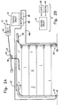
- Fig. 2A shows the components of the present invention which replace the prior art safety system.
- a light transmitter 45 and light receiver 46 which are substantially similar to the transmitter 25 and receiver 26 of the prior art are located in the opener enclosure 13 with the control circuit 16 which enclosure is typically mounted on the ceiling of the garage.
- the transmitter 45 is connected to an optical cable 47.
- the distal end of the cable has a lens arrangement 49 of a type known in the art.
- the lens arrangement 49 is mounted near the bottom of one side of the door opening 51 so that a light beam generated by the transmitter 45 is sent through the cable 47 and the lens arrangement 49 across the door opening.
- the receiver 46 is connected to an optical cable 48.
- the distal end of the cable has a lens arrangement 50 similar to the transmitter lens arrangement 49.
- the receiver lens arrangement 50 is mounted near the bottom of the garage door opening 52 on the side opposite the transmitter lens arrangement 49 so that the light beam is transmitted across the door opening through the lens arrangement 50 and optical cable 48 to the receiver 46.
- Plastic optical cables 47 and 48 are preferred as they are relatively inexpensive and durable, but glass or other types are suitable.
- the transmitter 45 sends a signal through the optical cable 47, through the lens arrangement 49, across the door opening, through the lens arrangement 50, through the optical cable 48, to the receiver 46.
- the preferred signal is infrared, but other frequencies are contemplated. Further, the signals can be pulsed or coded to prevent stray signals such as sunlight or reflections from giving erroneous indications.
- the receiver 46 is in communication with the control circuit 14 so that when the receiver 46 is receiving the signal, it provides an indication to the control circuit that there is no obstruction to closing of the garage door 11. This is the normal operating condition. When an obstruction 24 interrupts the signal, the signal does not reach the receiver 46. The receiver then indicates to the control circuit 14 that an obstruction is present.
- the control circuit 14 can prevent closing of the door 11 by preventing or stopping operation of the motor 16. If the door 11 is closing when an obstruction is detected, the motor 16 can be reversed to open the door.
- the transmitter 45 and receiver 46 can be located separately from the enclosure 13, but it is preferred that they remain in close proximity to the control circuit 14.
- FIG. 3 A typical lens and cable mounting configuration employing a bracket 53 mounted on the track 15 is shown in FIG. 3, but other configurations are contemplated.
- the lens could be mounted on or near the door frame or, as another example, FIG. 4 shows the lens 49 mounted on a retractable spring device 55 attached to the bottom of the door 11 so that when the door is closed the lens 49 and mount 55 are forced into the retracted position by the ground or garage floor.
- the configuration of FIG. 4 has the advantage that the light beam is always adjacent the leading edge of the door which is where obstacles will obstruct the door.
- the FIG. 4 configuration has the disadvantage that wear on the cable will increase and an unsecured loop can be created if the cable is not retracted when the door is open. Also, the mount may be knocked out of alignment or become stuck.
- FIG. 5 shows one case where the door mounting of FIG. 4 is superior to the frame mounting of FIG. 3.
- the trunk 60 of a car extends into the path of the garage door 11, but because it is elevated, it does not obstruct the beam 61a near the ground.
- a door mounted lens, FIG. 4 would detect the trunk 60 immediately before the door 11 reached the trunk 60.
- FIG. 6 shows how several beams 61a, 61b, and 61c can be directed across the door opening at different levels by installing several transmitter lenses 49a, 49b, and 49c and cables 47a, 47b, and 47c and several receiver lenses 50a, 50b, and 50c and cables 48a, 48b, and 48c. With multiple beams, obstacles which are not near the bottom of the door opening can be detected.
- FIG. 7 shows another alternative detection system in which the system uses only a single cable 70 which is connected to a combined transmitter/receiver 44.
- the cable has, at its end, a lens arrangement 71 of the type known in the art which is mounted as described above.
- a reflecting device 72 is mounted so that the transmitter part of the transmitter/receiver 44 sends a signal through the cable 70 and lens arrangement 71 across the door opening to the reflector 72 which reflects the signal back across the door opening through the lens arrangement 71 and cable 70 to the receiver part transmitter/receiver 44.
- the cable 70 can have multiple fiber optic elements or the signal can be multiplexed and transmitted and received through a single element.
- Similar configurations could include separate lenses, cables, reflectors and/or transmitter/receivers. Such a system is simpler and less costly because it has fewer components. Potential drawbacks include the need to clean the reflector periodically and possible inadvertent reflections, for example, from a reflective obstruction.
Landscapes
- Physics & Mathematics (AREA)
- General Physics & Mathematics (AREA)
- Life Sciences & Earth Sciences (AREA)
- General Life Sciences & Earth Sciences (AREA)
- Geophysics (AREA)
- Power-Operated Mechanisms For Wings (AREA)
- Burglar Alarm Systems (AREA)
- Geophysics And Detection Of Objects (AREA)
Claims (12)
- Motorbetriebenes Garagentor (11) zum Schließen einer Garagentoröffnung mit einer Hindernisfeststellsicherheitseinrichtung und mit einem motorbetriebenen Öffner (12), der mit dem Garagentor (11) zum Öffnen und Schließen des Garagentores (11) verbunden ist, einem Steuerschaltkreis (14), einem Lichtsender (45) zum Aussenden eines Lichtstrahls, und einem Lichtempfänger (46) zum Empfangen des Lichtstrahls, wobei der Öffner (12) einen Motor (16) aufweist, der entfernt von dem Garagentor (11) befestigt ist, wobei der Steuerschaltkreis (14) angrenzend an den Motor (16) angebracht ist und operativ mit dem Öffner (12) verbunden ist, um das Öffnen und Schließen des Garagentores (11) zu steuern, wobei der Empfänger (46) in Verbindung mit dem Steuerschaltkreis (14) steht und dem Steuerschaltkreis (14) anzeigt, ob er den Lichtstrahl empfängt, so daß, wenn er den Lichtstrahl nicht empfängt, der Steuerschaltkreis (14) das Schließen des Garagentores (11) aufhält, dadurch gekennzeichnet, daß der Lichtsender (45) mit dem Steuerschaltkreis (14) angrenzend an den Motor (16) angebracht ist; daß der Lichtempfänger (46) mit dem Steuerschaltkreis (14) angrenzend an den Motor (16) angebracht ist; daß ein Paar von Lichtübertragungsleitungen (47, 48) jeweils mit einem Ende (49, 50) an der Garagentoröffnung vorgesehen ist, wobei die Lichtübertragungsleitungen (47, 48) den Sender (45) und den Empfänger (46) mit der Garagentoröffnung verbinden, so daß der Lichtstrahl die Strecke von dem Sender (45) durch die Übertragungsleitungen und über die Garagentoröffnung zu dem Lichtempfänger (46) zurücklegen kann.
- Motorbetriebenes Garagentor nach Anspruch 1, wobei das Ende jeder der Übertragungsleitungen (47, 48) in der Nähe des Bodens einer Seite der Garagentoröffnung liegt.
- Motorbetriebenes Garagentor nach Anspruch 1, wobei ein Reflektor (72) gegenüber dem Ende einer der Übertragungsleitungen (70) angeordnet ist.
- Motorbetriebenes Garagentor nach Anspruch 1, wobei die Übertragungsleitung (47, 48) eine Faseroptik aufweist.
- Motorbetriebenes Garagentor nach Anspruch 1, wobei der Sender (45) einen Infrarotstrahl aussendet.
- Motorbetriebenes Garagentor nach Anspruch 1, wobei der Sender (45) einen gepulsten Strahl aussendet.
- Motorbetriebenes Garagentor nach Anspruch 1, wobei der Sender (45) einen kodierten Strahl aussendet.
- Motorbetriebenes Garagentor nach Anspruch 1, außerdem mit einem Gehäuse (13), in dem der Steuerschaltkreis (14) angeordnet ist, wobei der Sender (45) und der Empfänger (46) innerhalb des Gehäuses (13) angeordnet sind.
- Motorbetriebenes Garagentor nach Anspruch 1, wobei der Sender (45) den Strahl als einen über die Toröffnung gerichteten Strahl aussendet.
- Motorbetriebenes Garagentor nach Anspruch 1, wobei das Ende der Übertragungsleitungen (70) eine Linsenanordnung (71) zum Sammeln oder Ausrichten des Strahles umfaßt.
- Motorbetriebenes Garagentor nach Anspruch 1, wobei das Ende (49) der Übertragungsleitung (47) in der Nähe des Bodens an dem Garagentor angebracht ist.
- Motorbetriebenes Garagentor nach Anspruch 1, wobei wenigstens eines der Enden (49) von der Garagentoröffnung weg zurückschiebbar ist.
Applications Claiming Priority (3)
| Application Number | Priority Date | Filing Date | Title |
|---|---|---|---|
| US07/843,264 US5233185A (en) | 1992-02-28 | 1992-02-28 | Light beam detector for door openers using fiber optics |
| US843264 | 1992-02-28 | ||
| CA002091843A CA2091843C (en) | 1992-02-28 | 1993-03-17 | Light beam detector for door operators using fiber optics |
Publications (2)
| Publication Number | Publication Date |
|---|---|
| EP0557589A1 EP0557589A1 (de) | 1993-09-01 |
| EP0557589B1 true EP0557589B1 (de) | 1997-03-12 |
Family
ID=25676002
Family Applications (1)
| Application Number | Title | Priority Date | Filing Date |
|---|---|---|---|
| EP92120219A Expired - Lifetime EP0557589B1 (de) | 1992-02-28 | 1992-11-26 | Lichtstrahldetektor für Türöffner unter Verwendung optischer Fasern |
Country Status (3)
| Country | Link |
|---|---|
| US (1) | US5233185A (de) |
| EP (1) | EP0557589B1 (de) |
| CA (1) | CA2091843C (de) |
Families Citing this family (52)
| Publication number | Priority date | Publication date | Assignee | Title |
|---|---|---|---|---|
| US5633778A (en) * | 1994-01-28 | 1997-05-27 | The Chamberlain Group, Inc. | Infrared signal interface for use with barrier door operator |
| US5552767A (en) * | 1994-02-14 | 1996-09-03 | Toman; John R. | Assembly for, and method of, detecting and signalling when an object enters a work zone |
| US5465033A (en) * | 1994-05-27 | 1995-11-07 | Texas Optoelectronics, Inc. | Universal safety system for automatic doors |
| DE19515365C2 (de) * | 1995-05-02 | 1997-11-20 | Deutsche Forsch Luft Raumfahrt | Faseroptische Lichtschranke |
| EP1478085A3 (de) * | 1995-06-06 | 2005-07-13 | The Chamberlain Group, Inc. | Bewegliche Barrierenbedienvorrichtung mit Lernfähigkeit für Kraft und Position |
| US5661804A (en) * | 1995-06-27 | 1997-08-26 | Prince Corporation | Trainable transceiver capable of learning variable codes |
| US5798681A (en) * | 1995-09-06 | 1998-08-25 | Chang; Nai-Wen | Garage door position indicator |
| IT237463Y1 (it) * | 1997-04-30 | 2000-09-13 | Campisa Srl | Serranda ad azionamento rapido in particolare per aperture di edificiindustriali |
| US6020703A (en) * | 1997-06-30 | 2000-02-01 | Telmet; Juhan | Garage door opener |
| US5929580A (en) * | 1997-08-05 | 1999-07-27 | Wayne-Dalton Corp. | System and related methods for detecting an obstruction in the path of a garage door controlled by an open-loop operator |
| DE19739543A1 (de) * | 1997-09-09 | 1999-03-11 | Efaflex Inzeniring D O O Ljubl | Sicherheitseinrichtung für motorisch angetriebene Tore |
| DE19739544A1 (de) * | 1997-09-09 | 1999-03-11 | Efaflex Inzeniring D O O Ljubl | Sicherheitseinrichtung für motorisch angetriebene Systeme |
| US6082046A (en) * | 1998-02-25 | 2000-07-04 | Simmons; Kevin A. | Overhead door sensor mounting bracket |
| US6133703A (en) | 1998-03-12 | 2000-10-17 | The Chamberlain Group, Inc. | Bi-directional pass-point system for controlling the operation of movable barriers |
| US6051947A (en) * | 1998-03-12 | 2000-04-18 | The Chamberlain Group, Inc. | Pass point system for controlling the operation of movable barriers |
| DE19826287A1 (de) * | 1998-06-12 | 1999-12-16 | Volkswagen Ag | Verfahren und Vorrichtung zur Sitzbelegungserkennung eines Fahrzeugsitzes |
| US6172475B1 (en) | 1998-09-28 | 2001-01-09 | The Chamberlain Group, Inc. | Movable barrier operator |
| GB2342989A (en) * | 1998-10-23 | 2000-04-26 | Integrated Design Limited | Detection system |
| US6388573B1 (en) | 1999-03-17 | 2002-05-14 | Jerry R. Smith | Motion detection system and methodology for accomplishing the same |
| GB2361308B (en) * | 1999-03-17 | 2002-04-10 | British Telecomm | Detection system |
| US6563278B2 (en) | 1999-07-22 | 2003-05-13 | Noostuff, Inc. | Automated garage door closer |
| US6326751B1 (en) | 1999-08-25 | 2001-12-04 | Wayne-Dalton Corp. | System and related methods for detecting and measuring the operational parameters of a garage door utilizing a lift cable system |
| US20010042820A1 (en) * | 2000-01-04 | 2001-11-22 | Wilson Robert H. | Optoelectronic system for an automatic vehicle door closure |
| DE10033077A1 (de) * | 2000-07-07 | 2002-01-17 | Sick Ag | Lichtgitter |
| US6936984B2 (en) | 2000-08-28 | 2005-08-30 | Lear Corporation | Method and system for detecting the position of a power window of a vehicle |
| US6651385B2 (en) * | 2000-10-02 | 2003-11-25 | Miller Edge, Inc. | Retractable non-contact sensor system |
| US6920717B2 (en) | 2000-10-02 | 2005-07-26 | Miller Edge, Inc. | Non-contact sensor system and mounting barrier |
| JP2003218679A (ja) * | 2002-01-25 | 2003-07-31 | Keyence Corp | 多光軸光電式安全装置 |
| US7057519B2 (en) * | 2002-04-30 | 2006-06-06 | The Chamberlain Group, Inc. | Automatic sensing of safe-operation sensor apparatus and method |
| US20050001573A1 (en) * | 2002-07-01 | 2005-01-06 | Bearge Miller | Non-contact safety system |
| US7755223B2 (en) * | 2002-08-23 | 2010-07-13 | The Chamberlain Group, Inc. | Movable barrier operator with energy management control and corresponding method |
| FR2851341B1 (fr) * | 2003-02-14 | 2005-04-22 | Etude Et Realisation Electroni | Systeme de detection optique d'objets ou de personnes |
| US6906307B2 (en) * | 2003-03-03 | 2005-06-14 | Mechanical Ingenuity Corp | Fail safe one wire interface for optical emitter-detector photo-eye systems with diagnostics |
| US7157689B1 (en) | 2003-10-28 | 2007-01-02 | Fraba Inc. | Optical edge sensing system with signal authentication |
| DE102004014182B4 (de) * | 2004-03-23 | 2007-04-12 | Hörmann KG Brockhagen | Tor |
| US7221288B2 (en) * | 2004-10-25 | 2007-05-22 | The Chamberlain Group, Inc. | Method and apparatus for using optical signal time-of-flight information to facilitate obstacle detection |
| FR2883584B1 (fr) * | 2005-03-25 | 2007-06-08 | Maviflex Sa Sa | Dispositif de detection d'un obstacle et de limitation d'effort d'un tablier d'une porte de manutention |
| US20070277943A1 (en) * | 2006-06-05 | 2007-12-06 | Rite-Hite Holding Corporation | Track and guide system for a door |
| US8037921B2 (en) * | 2006-06-05 | 2011-10-18 | Rite-Hite Holding Corporation | Track and guide system for a door |
| US7748431B2 (en) * | 2006-06-05 | 2010-07-06 | Rite-Hite Holding Corporation | Track and guide system for a door |
| ES2285953B1 (es) * | 2007-02-01 | 2008-09-01 | Jcm Technologies, S.A. | "sistema de puerta automatica con banda de seguridad y procedimiento que ejecuta dicho sistema". |
| EP2387924B1 (de) * | 2007-06-18 | 2024-09-04 | Gotohti.com Inc. | Verfahren zur Steuerung des Betriebs eines Ausgabemechanismus |
| US8375635B2 (en) | 2009-08-26 | 2013-02-19 | Richard Hellinga | Apparatus for opening and closing overhead sectional doors |
| DE102010000234B3 (de) * | 2010-01-27 | 2011-03-17 | Alpha Deuren International Bv | Sektionaltor |
| US8665065B2 (en) | 2011-04-06 | 2014-03-04 | The Chamberlain Group, Inc. | Barrier operator with power management features |
| US20130086841A1 (en) * | 2011-10-10 | 2013-04-11 | William M. Luper | Overhead Door Object Detection Apparatus |
| US8988213B2 (en) * | 2011-10-28 | 2015-03-24 | Cedes Ag | Safety device, closing device and evaluation unit |
| DE202012012514U1 (de) | 2012-02-22 | 2013-04-15 | Alpha Deuren International Bv | Spiraltor |
| DE102016014202B4 (de) * | 2016-11-17 | 2024-03-07 | Hörmann KG Brockhagen | Tor |
| DE102018104314A1 (de) * | 2018-02-26 | 2019-08-29 | Marantec Antriebs- Und Steuerungstechnik Gmbh & Co. Kg | Toranlage |
| DE102021134132A1 (de) * | 2021-12-21 | 2023-06-22 | Cedes Ag | Voreilende Schließkantensicherungsanordnung für eine Toreinrichtung sowie Toreinrichtung |
| US20250136002A1 (en) * | 2023-10-25 | 2025-05-01 | Fca Us Llc | System and method for operating a front trunk of an electric vehicle |
Family Cites Families (17)
| Publication number | Priority date | Publication date | Assignee | Title |
|---|---|---|---|---|
| US2994572A (en) * | 1957-05-29 | 1961-08-01 | Union Stock Yard & Transit Co Chicago | Refrigerated display counter with automatic door opening |
| US3430052A (en) * | 1967-08-23 | 1969-02-25 | Robert E Stephan | Photoelectric garage door closer serving to close door only after light beam has been broken and reestablished |
| US3805061A (en) * | 1973-04-23 | 1974-04-16 | Tyco Laboratories Inc | Object detecting apparatus |
| US4015122A (en) * | 1974-07-12 | 1977-03-29 | Rubinstein Walter M | Photo-electric object detection system |
| US4379289A (en) * | 1979-03-08 | 1983-04-05 | Gte Laboratories Incorporated | Fiber optics security system |
| GB2135292B (en) * | 1981-02-05 | 1985-04-17 | Minibar Ltd | Dispensing apparatus |
| US4501963A (en) * | 1981-11-03 | 1985-02-26 | Automatic Roller Doors, Australia, Pty., Ltd. | Reversing device for roller doors |
| US4539474A (en) * | 1982-06-21 | 1985-09-03 | Hondadenshigiken Co., Ltd. | Optical switch for an automatic door |
| US4698937A (en) * | 1983-11-28 | 1987-10-13 | The Stanley Works | Traffic responsive control system for automatic swinging door |
| US4701751A (en) * | 1984-11-09 | 1987-10-20 | Sackett Robert L | Pool alarm system |
| US4620181A (en) * | 1984-11-09 | 1986-10-28 | Sackett Robert L | Pool alarm system |
| JPH0325220Y2 (de) * | 1985-02-15 | 1991-05-31 | ||
| US4652205A (en) * | 1985-05-02 | 1987-03-24 | Robotic Vision Systems, Inc. | Robot cell safety system |
| FR2599532A1 (fr) * | 1986-05-30 | 1987-12-04 | Commissariat Energie Atomique | Dispositif de surveillance a fibres optiques |
| FR2626096B1 (fr) * | 1988-01-19 | 1992-02-14 | Breuil Sa | Appareil de comptage d'objets defilant |
| US4812810A (en) * | 1988-01-25 | 1989-03-14 | Whirlpool Corporation | Fiber optic door sensor for a domestic appliance |
| US4922168A (en) * | 1989-05-01 | 1990-05-01 | Genie Manufacturing, Inc. | Universal door safety system |
-
1992
- 1992-02-28 US US07/843,264 patent/US5233185A/en not_active Expired - Lifetime
- 1992-11-26 EP EP92120219A patent/EP0557589B1/de not_active Expired - Lifetime
-
1993
- 1993-03-17 CA CA002091843A patent/CA2091843C/en not_active Expired - Fee Related
Also Published As
| Publication number | Publication date |
|---|---|
| CA2091843C (en) | 1999-08-03 |
| EP0557589A1 (de) | 1993-09-01 |
| CA2091843A1 (en) | 1994-09-18 |
| US5233185A (en) | 1993-08-03 |
Similar Documents
| Publication | Publication Date | Title |
|---|---|---|
| EP0557589B1 (de) | Lichtstrahldetektor für Türöffner unter Verwendung optischer Fasern | |
| US7161319B2 (en) | Movable barrier operator having serial data communication | |
| US4922168A (en) | Universal door safety system | |
| US5191268A (en) | Continuously monitored supplemental obstruction detector for garage door operator | |
| EP0826095B1 (de) | Motorisch angetriebene lüftung eines fahrzeuges | |
| US7034682B2 (en) | Door with a safety antenna | |
| EP1091062B1 (de) | Antiklemmvorrichtung eines Türschlosses | |
| WO1995002108A1 (en) | Electrical link and sensor system for automatic sliding doors | |
| US20010042820A1 (en) | Optoelectronic system for an automatic vehicle door closure | |
| US7228883B1 (en) | Motorized barrier operator system utilizing multiple photo-eye safety system and methods for installing and using the same | |
| US20040095250A1 (en) | Apparatus and method for detecting an object | |
| US20020109078A1 (en) | Rotating light source system for detecting an obstruction in a space, for use in a mobile storage system | |
| EP1096093B1 (de) | Hinderniserkennung für ein Fenster | |
| CN216291512U (zh) | 一种ip66防护等级的铁路隧道应急照明控制装置 | |
| US6704471B1 (en) | System and method for detecting an obstruction in a power window | |
| EP1181429B1 (de) | Antriebsvorrichtung für bewegliche verschlussvorrichtung mit passivem infrarotdetektor | |
| KR100562529B1 (ko) | 광전 센서를 이용한 승강장 스크린도어 제어시스템 | |
| EP0501858A2 (de) | Betriebssicherer Behinderungsdetektor für Türöffner | |
| EP1096091A2 (de) | Hinderniserkenning für ein Fenster | |
| EP2146034A1 (de) | Sicherheitssystem für ein motorbetriebenes Tor oder Schiebetür | |
| KR950009483Y1 (ko) | 엘리베이터의 방범창 안전감지장치 | |
| EP1096092A1 (de) | Widerstandsdetektor für ein Fenster | |
| WO1993006327A1 (en) | A device in electrically operated sliding doors and the like | |
| EP1096090A1 (de) | Hindernisdetektor für ein Fenster | |
| EP1719866A2 (de) | Sicherheitssystem für automatisches Tor |
Legal Events
| Date | Code | Title | Description |
|---|---|---|---|
| PUAI | Public reference made under article 153(3) epc to a published international application that has entered the european phase |
Free format text: ORIGINAL CODE: 0009012 |
|
| AK | Designated contracting states |
Kind code of ref document: A1 Designated state(s): AT DE FR GB IT |
|
| 17P | Request for examination filed |
Effective date: 19940224 |
|
| 17Q | First examination report despatched |
Effective date: 19950222 |
|
| GRAG | Despatch of communication of intention to grant |
Free format text: ORIGINAL CODE: EPIDOS AGRA |
|
| GRAH | Despatch of communication of intention to grant a patent |
Free format text: ORIGINAL CODE: EPIDOS IGRA |
|
| GRAH | Despatch of communication of intention to grant a patent |
Free format text: ORIGINAL CODE: EPIDOS IGRA |
|
| GRAA | (expected) grant |
Free format text: ORIGINAL CODE: 0009210 |
|
| AK | Designated contracting states |
Kind code of ref document: B1 Designated state(s): AT DE FR GB IT |
|
| REF | Corresponds to: |
Ref document number: 150127 Country of ref document: AT Date of ref document: 19970315 Kind code of ref document: T |
|
| REF | Corresponds to: |
Ref document number: 69218172 Country of ref document: DE Date of ref document: 19970417 |
|
| ITF | It: translation for a ep patent filed | ||
| ET | Fr: translation filed | ||
| PLBE | No opposition filed within time limit |
Free format text: ORIGINAL CODE: 0009261 |
|
| STAA | Information on the status of an ep patent application or granted ep patent |
Free format text: STATUS: NO OPPOSITION FILED WITHIN TIME LIMIT |
|
| 26N | No opposition filed | ||
| REG | Reference to a national code |
Ref country code: GB Ref legal event code: IF02 |
|
| PGFP | Annual fee paid to national office [announced via postgrant information from national office to epo] |
Ref country code: AT Payment date: 20030508 Year of fee payment: 11 |
|
| PGFP | Annual fee paid to national office [announced via postgrant information from national office to epo] |
Ref country code: FR Payment date: 20030512 Year of fee payment: 11 |
|
| PGFP | Annual fee paid to national office [announced via postgrant information from national office to epo] |
Ref country code: GB Payment date: 20030516 Year of fee payment: 11 |
|
| PGFP | Annual fee paid to national office [announced via postgrant information from national office to epo] |
Ref country code: DE Payment date: 20030527 Year of fee payment: 11 |
|
| PG25 | Lapsed in a contracting state [announced via postgrant information from national office to epo] |
Ref country code: GB Free format text: LAPSE BECAUSE OF NON-PAYMENT OF DUE FEES Effective date: 20031126 Ref country code: AT Free format text: LAPSE BECAUSE OF NON-PAYMENT OF DUE FEES Effective date: 20031126 |
|
| PG25 | Lapsed in a contracting state [announced via postgrant information from national office to epo] |
Ref country code: DE Free format text: LAPSE BECAUSE OF NON-PAYMENT OF DUE FEES Effective date: 20040602 |
|
| GBPC | Gb: european patent ceased through non-payment of renewal fee |
Effective date: 20031126 |
|
| PG25 | Lapsed in a contracting state [announced via postgrant information from national office to epo] |
Ref country code: FR Free format text: LAPSE BECAUSE OF NON-PAYMENT OF DUE FEES Effective date: 20040730 |
|
| REG | Reference to a national code |
Ref country code: FR Ref legal event code: ST |
|
| PG25 | Lapsed in a contracting state [announced via postgrant information from national office to epo] |
Ref country code: IT Free format text: LAPSE BECAUSE OF NON-PAYMENT OF DUE FEES;WARNING: LAPSES OF ITALIAN PATENTS WITH EFFECTIVE DATE BEFORE 2007 MAY HAVE OCCURRED AT ANY TIME BEFORE 2007. THE CORRECT EFFECTIVE DATE MAY BE DIFFERENT FROM THE ONE RECORDED. Effective date: 20051126 |