EP0563464A1 - Tent frame binding device - Google Patents
Tent frame binding device Download PDFInfo
- Publication number
- EP0563464A1 EP0563464A1 EP92203552A EP92203552A EP0563464A1 EP 0563464 A1 EP0563464 A1 EP 0563464A1 EP 92203552 A EP92203552 A EP 92203552A EP 92203552 A EP92203552 A EP 92203552A EP 0563464 A1 EP0563464 A1 EP 0563464A1
- Authority
- EP
- European Patent Office
- Prior art keywords
- frame member
- slots
- binding body
- frame
- recesses
- Prior art date
- Legal status (The legal status is an assumption and is not a legal conclusion. Google has not performed a legal analysis and makes no representation as to the accuracy of the status listed.)
- Granted
Links
Images

Classifications
-
- E—FIXED CONSTRUCTIONS
- E04—BUILDING
- E04H—BUILDINGS OR LIKE STRUCTURES FOR PARTICULAR PURPOSES; SWIMMING OR SPLASH BATHS OR POOLS; MASTS; FENCING; TENTS OR CANOPIES, IN GENERAL
- E04H15/00—Tents or canopies, in general
- E04H15/32—Parts, components, construction details, accessories, interior equipment, specially adapted for tents, e.g. guy-line equipment, skirts, thresholds
- E04H15/34—Supporting means, e.g. frames
- E04H15/44—Supporting means, e.g. frames collapsible, e.g. breakdown type
- E04H15/48—Supporting means, e.g. frames collapsible, e.g. breakdown type foldable, i.e. having pivoted or hinged means
-
- Y—GENERAL TAGGING OF NEW TECHNOLOGICAL DEVELOPMENTS; GENERAL TAGGING OF CROSS-SECTIONAL TECHNOLOGIES SPANNING OVER SEVERAL SECTIONS OF THE IPC; TECHNICAL SUBJECTS COVERED BY FORMER USPC CROSS-REFERENCE ART COLLECTIONS [XRACs] AND DIGESTS
- Y10—TECHNICAL SUBJECTS COVERED BY FORMER USPC
- Y10T—TECHNICAL SUBJECTS COVERED BY FORMER US CLASSIFICATION
- Y10T403/00—Joints and connections
- Y10T403/32—Articulated members
- Y10T403/32254—Lockable at fixed position
- Y10T403/32262—At selected angle
- Y10T403/32319—At selected angle including pivot stud
- Y10T403/32409—Members locked in axial alignment
-
- Y—GENERAL TAGGING OF NEW TECHNOLOGICAL DEVELOPMENTS; GENERAL TAGGING OF CROSS-SECTIONAL TECHNOLOGIES SPANNING OVER SEVERAL SECTIONS OF THE IPC; TECHNICAL SUBJECTS COVERED BY FORMER USPC CROSS-REFERENCE ART COLLECTIONS [XRACs] AND DIGESTS
- Y10—TECHNICAL SUBJECTS COVERED BY FORMER USPC
- Y10T—TECHNICAL SUBJECTS COVERED BY FORMER US CLASSIFICATION
- Y10T403/00—Joints and connections
- Y10T403/34—Branched
- Y10T403/341—Three or more radiating members
-
- Y—GENERAL TAGGING OF NEW TECHNOLOGICAL DEVELOPMENTS; GENERAL TAGGING OF CROSS-SECTIONAL TECHNOLOGIES SPANNING OVER SEVERAL SECTIONS OF THE IPC; TECHNICAL SUBJECTS COVERED BY FORMER USPC CROSS-REFERENCE ART COLLECTIONS [XRACs] AND DIGESTS
- Y10—TECHNICAL SUBJECTS COVERED BY FORMER USPC
- Y10T—TECHNICAL SUBJECTS COVERED BY FORMER US CLASSIFICATION
- Y10T403/00—Joints and connections
- Y10T403/44—Three or more members connected at single locus
- Y10T403/443—All encompassed
Definitions
- the present invention relates to a tent frame binding device in which the frame members of a tent can be assembled and disassembled in a speedy manner.
- a prior art of the tent frame binding device is disclosed in Korean Utility Model Publication No. 90-2935 and U.S. Patent No. 4,750,509, both of which were granted to the present applicant, and the structure of which is illustrated in Figures 5 and 6.
- a plurality of slots 70 are formed angularly separated on a securing disc 100, and a pair of fastening recesses 90 having a engaging step 80 therein are formed in each of the slots 70.
- the end portion of each of frame members 30 is T-shaped, because it has a pair of fastening pins 40.
- each of the frame members 30 is inserted into each of the slots 70 of the securing disc 100, and then, the frame member 30 is pivoted one half rounds so that the fastening pins 40 of the frame member 30 should be disposed within the two fastening recesses 90. Then the frame member 30 is pulled up, so that the fastening pins 40 should be engaged with the engaging step 80. Then if the frame members 30 are laid horizontally and are pushed down, the frame members 30 are lifted up, with each of the end portions of the frame members 30 being settled on a settling bottom 60, resulting in that the fastening pins 40 are assembled into the fastening recess 90.
- each of the frame members has to be sufficiently inserted into each of the slots, the frame members have to be pulled up, and have to be turned by 180° so as for the fastening pins to be aligned with the fastening recess. Then the frame members have to be laid down, and have to be pushed down, thereby making the fastening pins engaged with the engaging step.
- the frame members cannot be bound by a single manipulation, and much inconvenience is accompanied.
- each of the frame members has to be made to stand upright, and therefore, the space of the assembling place has to be large, and non-skilled persons are forced to experience much difficulty in performing the assembling work, thereby aggravating the productivity.
- the present invention is intended to overcome the above described disadvantages of the conventional techniques.
- a binding body is provided with a plurality of slots angularly separated for fitting frame members, a pair of U shaped fastening recesses are formed on the side walls of the slots, supporting shafts formed on the both sides of the fastening portion of the frame member are fitted into the fastening recesses, and the top of the binding body is covered with a securing plate.
- the slots of the binding body are formed deep, inclined engaging steps are formed only on the rear portion of the slots, and an inclined portion is formed on the rear portions of the supporting shafts of the frame members, so that, when the frame members are inserted into the slots, the inclined portions should be supported by the engaging steps of the rear portions of the slots.
- a binding body 1 of the present invention has a contour of narrow top and wide bottom, and a plurality of slots 3 are formed around the binding body 1 angularly separated.
- Each of frame member fastening parts 2 is pivotally inserted into each of the slots 3.
- the slots 3 extend deep into the center of the binding body 1, and a front portion F of the slot 3 is open upwardly and downwardly, while only an engaging step 4 of a rear portion S of the slot 3 closes the top of the slot to support the frame member fastening part 2.
- a pair of U shaped fastening recesses 5 are formed on a front portion F of the side walls of the slot 3, the recesses 5 being open upwardly.
- the frame member fastening part 2 which is coupled with the slot 3 is provided with a supporting shaft 6 and an inclined portion 7.
- the supporting shaft 6 projects to left and right from the body of the fastening part 2, and has the shape of a circular rod, so that it can be settled into the fastening recesses 5 of the slot 3.
- the inclined portion 7 formed at the rear of the supporting shaft 6 is inserted deep into the rear portion S of the slot 3 to be supported by the engaging step 4.
- the inner surface of the engaging step 4 is inclined correspondingly with the inclined portion 7.
- the top of the binding body 1 is covered with a securing plate 8, which is fastened to the binding body 1 by driving a bolt 9 through a hole of the securing plate 8 into a thread hole 10 of the binding body 1.
- the securing plate 8 is intended to prevent the departure of the frame member fastening part 2 from the slot 2.
- the frame member fastening part 2 which has the shape of a socket has an insertion hole 14 for fitting a frame member 13, with a key 15 being projected within the hole 14.
- the frame member 13 is provided with a flat face 16, so that the frame member 13 cannot be turned, with the flat face 16 and the key 15 being coupled together.
- the tent frame binding device of the present invention constituted as described above, if a frame member 13 is to be fitted into the frame member fastening part 2, the frame member 13 is inserted into the insertion hole 14 of the part 2, with the key 15 and the flat portion 16 being aligned together. If the frame member fastening part 2 is to be joined to the binding body 1, the frame member fastening part 2 is inserted into the slot 3 in a slightly inclined manner, and then, the supporting shaft 6 is made to be settled into the fastening recesses 5, with the inclined portion 7 being disposed on the rear portion S of the slot 3.
- the frame members 13 After the insertion of the frame member fastening parts 2 into the binding body 1, the frame members 13 are laid down horizontally, and the securing plate 8 is put on the top of the binding body 1 to fasten the securing plate 8 to the binding body 1 by driving the bolt 9 through the plate 8 into the body 1, thereby completing the assembling of the tent frame. If the frame is to be disassembled for a repair or the like, the bolt 9 is unfastened, and the plate 8 is removed. Then the relevant frame member fastening part 2 is lifted up, and pulled out in an easy manner.
- the binding body 1 is provided with a plurality of slots 3 angularly separated, and a pair of fastening recesses 5 are formed in each of the slots 3, so that the frame member fastening parts 2 can be easily assembled into the slots 3.
- an engaging step 4 is formed on the rear portion S of the slot 3, so that the inclined portion 7 can be supported on it. Therefore, when the tent is unfolded, the supporting force is spread to the inclined portions 7, so that the supporting shafts 6 should not be over-burdened. Consequently, the accumulation of stress on the supporting shafts 6 can be avoided. Further, no special skill is required in assembling and disassembling the frame members, so that the user should be able to easily repair the tent.
- the tent frame binding device includes a binding body 1 and a plurality of frame member fastening parts 2 as in the case of the first embodiment described above.
- a plurality of slots 3 are formed around the binding body 1 for inserting a frame member fastening part 2 into each of the slots 3.
- a pair of supporting shafts 11 are formed on the side walls of each of the slots 3, and an inclined engaging step 4 is formed on the rear portion S of the slots 3.
- a pair of recesses 12 are formed on the left and right sides of the frame member fastening part 2, with the recesses 12 being opened downwardly, so that the recesses 12 can be coupled with the supporting shafts 11 of the slot 3.
- the tent frame binding device of the present invention makes it possible to assemble and disassemble the frame members to and from the binding body in a speedy manner.
Landscapes
- Engineering & Computer Science (AREA)
- Architecture (AREA)
- Civil Engineering (AREA)
- Structural Engineering (AREA)
- Tents Or Canopies (AREA)
- Mutual Connection Of Rods And Tubes (AREA)
- Seal Device For Vehicle (AREA)
- Basic Packing Technique (AREA)
- Making Paper Articles (AREA)
- Body Structure For Vehicles (AREA)
- Clamps And Clips (AREA)
Abstract
Description
- The present invention relates to a tent frame binding device in which the frame members of a tent can be assembled and disassembled in a speedy manner.
- A prior art of the tent frame binding device is disclosed in Korean Utility Model Publication No. 90-2935 and U.S. Patent No. 4,750,509, both of which were granted to the present applicant, and the structure of which is illustrated in Figures 5 and 6. As shown in these drawings, a plurality of
slots 70 are formed angularly separated on asecuring disc 100, and a pair of fasteningrecesses 90 having aengaging step 80 therein are formed in each of theslots 70. The end portion of each offrame members 30 is T-shaped, because it has a pair offastening pins 40. First, each of theframe members 30 is inserted into each of theslots 70 of thesecuring disc 100, and then, theframe member 30 is pivoted one half rounds so that thefastening pins 40 of theframe member 30 should be disposed within the twofastening recesses 90. Then theframe member 30 is pulled up, so that thefastening pins 40 should be engaged with theengaging step 80. Then if theframe members 30 are laid horizontally and are pushed down, theframe members 30 are lifted up, with each of the end portions of theframe members 30 being settled on a settlingbottom 60, resulting in that the fasteningpins 40 are assembled into thefastening recess 90. On the other hand, if theframe members 30 are to be disengaged from thesecuring disc 100, theframe members 30 are made to stand upright, and a slight force is applied, so that thefastening pins 40 which have been supported on theengaging step 80 of thefastening recess 90 should depart therefrom. - In the tent frame binding device of the prior art which is constituted as described above, the process of forming the fastening recess and the engaging steps within the securing disc is very difficult and complicated. Therefore, many steps of manufacturing process is required, and much time is consumed, with the result that the manufacturing cost is increased. Further, when assembling the tent frames, each of the frame members has to be sufficiently inserted into each of the slots, the frame members have to be pulled up, and have to be turned by 180° so as for the fastening pins to be aligned with the fastening recess. Then the frame members have to be laid down, and have to be pushed down, thereby making the fastening pins engaged with the engaging step. Thus the frame members cannot be bound by a single manipulation, and much inconvenience is accompanied. Particularly, when assembling the frame members, each of the frame members has to be made to stand upright, and therefore, the space of the assembling place has to be large, and non-skilled persons are forced to experience much difficulty in performing the assembling work, thereby aggravating the productivity.
- Another problem is seen in the fastening portions of the frame members.
- That is, when the tent is unfolded into a dome shaped tent, with the frame members being deflected, the supporting force is focused on the fastening pins. Consequently, much stress is accumulated on the fastening pins, and therefore, the frame members become weak after some use, with the possible result that the fastening pins may be broken or damaged.
- The present invention is intended to overcome the above described disadvantages of the conventional techniques.
- Therefore it is the object of the present invention to provide a tent frame binding device in which the structure of the fastening portion of the frame members is simple, the fastening portions of the frame members cannot easily depart, and the assembling work can be speedily carried out by fitting only the tips of the frame members.
- In achieving the above object, a binding body is provided with a plurality of slots angularly separated for fitting frame members, a pair of U shaped fastening recesses are formed on the side walls of the slots, supporting shafts formed on the both sides of the fastening portion of the frame member are fitted into the fastening recesses, and the top of the binding body is covered with a securing plate.
- It is another object of the present invention to provide a tent frame binding device in which the rear portions of the supporting shafts have a strong strength, so that, when the tent is unfolded, the distress of the supporting shafts should be greatly alleviated.
- In achieving the above object, the slots of the binding body are formed deep, inclined engaging steps are formed only on the rear portion of the slots, and an inclined portion is formed on the rear portions of the supporting shafts of the frame members, so that, when the frame members are inserted into the slots, the inclined portions should be supported by the engaging steps of the rear portions of the slots.
- The above objects and other advantages of the present invention will become more apparent by describing in detail the preferred embodiment of the present invention with reference to the attached drawings in which:
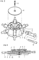
- Figure 1 is an exploded perspective view of the tent frame binding device according to the present invention;
- Figure 2 is a sectional view of the device of Figure 1;
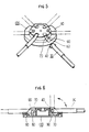
- Figure 3 illustrates another embodiment of the tent frame binding device according to the present invention;
- Figure 4 is a sectional view of the device of Figure 3;
- Figure 5 is a perspective view showing the structure of the conventional tent frame binding device; and
- Figure 6 is a sectional view of the device of Figure 5.
- A binding body 1 of the present invention has a contour of narrow top and wide bottom, and a plurality of
slots 3 are formed around the binding body 1 angularly separated. Each of frame member fasteningparts 2 is pivotally inserted into each of theslots 3. Theslots 3 extend deep into the center of the binding body 1, and a front portion F of theslot 3 is open upwardly and downwardly, while only anengaging step 4 of a rear portion S of theslot 3 closes the top of the slot to support the frame member fasteningpart 2. Meanwhile, a pair of U shaped fastening recesses 5 are formed on a front portion F of the side walls of theslot 3, the recesses 5 being open upwardly. - The frame member fastening
part 2 which is coupled with theslot 3 is provided with a supporting shaft 6 and aninclined portion 7. The supporting shaft 6 projects to left and right from the body of the fasteningpart 2, and has the shape of a circular rod, so that it can be settled into the fastening recesses 5 of theslot 3. Theinclined portion 7 formed at the rear of the supporting shaft 6 is inserted deep into the rear portion S of theslot 3 to be supported by theengaging step 4. The inner surface of theengaging step 4 is inclined correspondingly with theinclined portion 7. - The top of the binding body 1 is covered with a
securing plate 8, which is fastened to the binding body 1 by driving abolt 9 through a hole of thesecuring plate 8 into athread hole 10 of the binding body 1. Thesecuring plate 8 is intended to prevent the departure of the frame member fasteningpart 2 from theslot 2. - Further, the frame member fastening
part 2 which has the shape of a socket has aninsertion hole 14 for fitting aframe member 13, with akey 15 being projected within thehole 14. Theframe member 13 is provided with aflat face 16, so that theframe member 13 cannot be turned, with theflat face 16 and thekey 15 being coupled together. - In the tent frame binding device of the present invention constituted as described above, if a
frame member 13 is to be fitted into the frame member fasteningpart 2, theframe member 13 is inserted into theinsertion hole 14 of thepart 2, with thekey 15 and theflat portion 16 being aligned together. If the frame member fasteningpart 2 is to be joined to the binding body 1, the frame member fasteningpart 2 is inserted into theslot 3 in a slightly inclined manner, and then, the supporting shaft 6 is made to be settled into the fastening recesses 5, with theinclined portion 7 being disposed on the rear portion S of theslot 3. - After the insertion of the frame member fastening
parts 2 into the binding body 1, theframe members 13 are laid down horizontally, and thesecuring plate 8 is put on the top of the binding body 1 to fasten thesecuring plate 8 to the binding body 1 by driving thebolt 9 through theplate 8 into the body 1, thereby completing the assembling of the tent frame. If the frame is to be disassembled for a repair or the like, thebolt 9 is unfastened, and theplate 8 is removed. Then the relevant frame member fasteningpart 2 is lifted up, and pulled out in an easy manner. - In other words, the binding body 1 is provided with a plurality of
slots 3 angularly separated, and a pair of fastening recesses 5 are formed in each of theslots 3, so that the frame member fasteningparts 2 can be easily assembled into theslots 3. Further, anengaging step 4 is formed on the rear portion S of theslot 3, so that theinclined portion 7 can be supported on it. Therefore, when the tent is unfolded, the supporting force is spread to theinclined portions 7, so that the supporting shafts 6 should not be over-burdened. Consequently, the accumulation of stress on the supporting shafts 6 can be avoided. Further, no special skill is required in assembling and disassembling the frame members, so that the user should be able to easily repair the tent. - Now the second embodiment of the present invention will be described.
- As shown in Figures 3 and 4, the tent frame binding device includes a binding body 1 and a plurality of frame member fastening
parts 2 as in the case of the first embodiment described above. A plurality ofslots 3 are formed around the binding body 1 for inserting a frame member fasteningpart 2 into each of theslots 3. A pair of supporting shafts 11 are formed on the side walls of each of theslots 3, and an inclinedengaging step 4 is formed on the rear portion S of theslots 3. A pair ofrecesses 12 are formed on the left and right sides of the frame member fasteningpart 2, with therecesses 12 being opened downwardly, so that therecesses 12 can be coupled with the supporting shafts 11 of theslot 3. At the rear of therecesses 12 of the frame member fasteningpart 2, there is formed aninclined portion 7 so as for it to be coupled with the rear portion S of theslot 3 of the binding body 1. Thus therecesses 12 of the frame member fasteningpart 2 are coupled with the supporting shafts 11 of theslots 3, and then, asecuring plate 8 is fastened to the top of the binding body 1 by driving abolt 9 through thesecuring plate 8 into the top of the binding body 1. - The tent frame binding device of the present invention makes it possible to assemble and disassemble the frame members to and from the binding body in a speedy manner.
Claims (3)
- A tent frame binding device including a binding body 1, a plurality of slots 3 formed around said binding body 1, and a plurality of frame member fastening parts 2 for being joined into said slots 3,
the device further comprising:
a pair of fastening recesses 5 formed on the side walls of each of said slots 3, said recesses 5 being open upwardly;
an inclined engaging step 4 formed on the upper portion of the rear portion S of said slot 3;
a supporting shaft 6 formed on the top of said frame member fastening part 2, said supporting shaft 6 projecting to left and right of said frame member fastening part 2;
an inclined portion 7 formed on said frame member fastening part 2 and at the rear of said supporting shaft 6 so as for said inclined portion 7 to be coupled with said inclined engaging step 4; and
a securing plate 8 for being fastened to the top of said binding body 1,
whereby inserting said frame member fastening part 2 into said slots 3, and fastening said securing plate 8 to the top of said binding body 1 by driving a bolt 9 through said securing plate 8 into said binding body 1. - The tent frame binding device as claimed in claim 1, wherein supporting shafts 11 are formed on the side walls of said slot 3 of said binding body 1, and said frame member fastening part 2 is provided with a pair of recesses 12 on the sides thereof so as for said recesses 12 to be coupled with said supporting shafts 11 of said slot 3.
- The tent frame binding device as claimed in claim 1, wherein a key 15 is provided in an insertion hole 14 of said frame member fastening part 2, and a flat face 16 is formed on a frame member 13, so as for said key 15 and said flat face 16 to be aligned, when inserting said frame member 13 into the hole 14 of said frame member fastening part 2.
Applications Claiming Priority (6)
| Application Number | Priority Date | Filing Date | Title |
|---|---|---|---|
| KR539992 | 1992-04-02 | ||
| KR920005399 | 1992-04-02 | ||
| KR9205399U | 1992-04-02 | ||
| KR9212204U | 1992-07-03 | ||
| KR92012204U KR950009920Y1 (en) | 1992-04-02 | 1992-07-03 | Connecter for a tent |
| KR1220492 | 1992-07-03 |
Publications (2)
| Publication Number | Publication Date |
|---|---|
| EP0563464A1 true EP0563464A1 (en) | 1993-10-06 |
| EP0563464B1 EP0563464B1 (en) | 1998-03-04 |
Family
ID=26629007
Family Applications (1)
| Application Number | Title | Priority Date | Filing Date |
|---|---|---|---|
| EP92203552A Expired - Lifetime EP0563464B1 (en) | 1992-04-02 | 1992-11-18 | Tent frame binding device |
Country Status (14)
| Country | Link |
|---|---|
| US (1) | US5328286A (en) |
| EP (1) | EP0563464B1 (en) |
| JP (1) | JPH083617Y2 (en) |
| CN (1) | CN1030790C (en) |
| AT (1) | ATE163723T1 (en) |
| AU (1) | AU639189B1 (en) |
| CA (1) | CA2083222C (en) |
| CZ (1) | CZ281284B6 (en) |
| DE (1) | DE69224620T2 (en) |
| DK (1) | DK0563464T3 (en) |
| ES (1) | ES2113917T3 (en) |
| HU (1) | HU212285B (en) |
| PL (1) | PL298343A1 (en) |
| SK (1) | SK27993A3 (en) |
Cited By (8)
| Publication number | Priority date | Publication date | Assignee | Title |
|---|---|---|---|---|
| EP0704586A1 (en) * | 1994-09-30 | 1996-04-03 | Folkert Johan Bernard Praktiek | Tent frame and hinge |
| EP0684355A3 (en) * | 1994-05-26 | 1996-06-19 | Fox Design Int | A tent or canopy frame device. |
| DE19633762C1 (en) * | 1995-02-27 | 1998-04-23 | Baejin Corp | Foldable tent frame and tent with it |
| EP0889180A1 (en) * | 1997-07-04 | 1999-01-07 | Manufacture Stephanoise De Transformations Textiles M.S.T.T., (SA Conseil d'Administration) | Connecting device for tent arches |
| FR2765607A1 (en) * | 1997-07-04 | 1999-01-08 | Manuf Stephanoise De Transform | Connector for joining frame sections in domed tents with integral frames |
| DE10311665B3 (en) * | 2003-01-21 | 2004-12-30 | Chen, Yeong-Shu | Quick-pitch/strike tent for camping has frame having multiple poles which are pivotably connected by joints to erect frame together with cloth housing when pitching tent, otherwise, joints are struck to strike frame and cloth housing |
| EP2083134A1 (en) | 2008-01-26 | 2009-07-29 | Yücel Atiker | Supporting framework for mountable flat material, particularly in the form of hollow bodies |
| ITPN20090012A1 (en) * | 2009-02-09 | 2010-08-10 | Shadelab S R L | "JOINT FOR STRUCTURAL ELEMENTS OF A FRAME FOR TENTS" |
Families Citing this family (70)
| Publication number | Priority date | Publication date | Assignee | Title |
|---|---|---|---|---|
| DE29500055U1 (en) * | 1995-01-03 | 1995-02-23 | Koch Konstruktive Membranen GmbH & Co. KG, 83253 Rimsting | Holding device for anchoring single or multi-layered sheets to a stationary component |
| US5797695A (en) * | 1995-09-01 | 1998-08-25 | Prusmack; A. Jon | Articulating hub asssembly |
| WO1997023746A1 (en) * | 1995-12-22 | 1997-07-03 | Kelsey Hayes Company | Quick-connect arrangement for high density hydraulic lines for anti-lock brake and/or traction control systems |
| US5785535A (en) * | 1996-01-17 | 1998-07-28 | International Business Machines Corporation | Computer system with surface mount socket |
| US5943837A (en) * | 1996-01-30 | 1999-08-31 | Tvi Corporation | Quick erect shelter apparatus |
| US5927363A (en) * | 1997-11-12 | 1999-07-27 | Olsen; Todd C. | Prefabricated collapsible awning frame system |
| US6244011B1 (en) | 1998-09-21 | 2001-06-12 | Tvi Corporation | Inverted V-shaped display framework |
| US6516823B1 (en) * | 1999-10-21 | 2003-02-11 | Cosco Management, Inc. | Playyard canopy |
| US6591571B2 (en) * | 2000-02-02 | 2003-07-15 | Skyline Displays, Inc. | Hub assembly for collapsible display panel |
| US20030163966A1 (en) * | 2002-03-01 | 2003-09-04 | Reynolds Glenn A. | Method and apparatus for cladding elongated structural members |
| US7376993B2 (en) * | 2003-05-07 | 2008-05-27 | Kolcraft Enterprises | Play gyms and methods of operating the same |
| US6966813B2 (en) * | 2003-05-14 | 2005-11-22 | Joseph Donahue | Modular construction system and method of constructing toy structures |
| WO2005028784A1 (en) * | 2003-09-25 | 2005-03-31 | In-Young Jung | One-touch type foldable tent |
| DE202005017822U1 (en) * | 2005-11-14 | 2006-04-06 | Schneider, Michael | Washer with keyholes, circlips and rods for constructing geodesic frameworks |
| US7703464B2 (en) * | 2007-08-31 | 2010-04-27 | Oliver Joen-An Ma | Quick connector for shade structure |
| US20090093182A1 (en) * | 2007-10-05 | 2009-04-09 | Cranium, Inc. | Structure building toy |
| CN201129060Y (en) | 2007-11-30 | 2008-10-08 | 厦门革新金属制造有限公司 | Tent top connector |
| US8590554B2 (en) | 2007-11-30 | 2013-11-26 | Ki Ho Jin | Foldable tent with integrated ventilation system |
| US7891367B2 (en) | 2008-04-17 | 2011-02-22 | Oliver Joen-An Ma | Quick connector hub for shade structure |
| US8186369B2 (en) * | 2008-05-14 | 2012-05-29 | Swimways Corporation | Collapsible shelter |
| CN201252900Y (en) * | 2008-09-05 | 2009-06-10 | 马准安 | Umbrella-rid angle adjustment device |
| US8666058B2 (en) * | 2009-09-11 | 2014-03-04 | Freescale Semiconductor, Inc. | Time domain adaptive filter bank for network echo reduction or cancellation |
| US20110079261A1 (en) * | 2009-10-07 | 2011-04-07 | Sportsman Corporation | Joint assembly |
| US20120125267A1 (en) * | 2010-11-23 | 2012-05-24 | Sara Kelly | Canine chew pet toy |
| CN102146742B (en) * | 2011-04-02 | 2012-07-04 | 咸世一 | Tent brace connector |
| CN203129697U (en) | 2013-02-05 | 2013-08-14 | 客贝利(厦门)休闲用品有限公司 | Tent frame pole |
| US9587660B2 (en) * | 2011-08-05 | 2017-03-07 | Advantek Marketing, Inc. | Connector |
| CN102425331A (en) * | 2011-12-29 | 2012-04-25 | 陈焕奎 | Foldable-type tent |
| CN102535945A (en) * | 2012-01-18 | 2012-07-04 | 金祚献 | Top support structure of tent frame |
| CN103371579B (en) | 2012-04-19 | 2015-12-23 | 宁波万汇休闲用品有限公司 | Quick linked bone up-down runner structure and relevant parachute kit and quick linked bone method |
| CN203034904U (en) | 2012-11-29 | 2013-07-03 | 客贝利(厦门)休闲用品有限公司 | Tent top folding and unfolding mechanism |
| US8950417B2 (en) | 2012-12-28 | 2015-02-10 | Westfield Outdoor, Inc. | Articulating pole hub for a collapsible shelter and method of forming a collapsible shelter |
| US9192215B2 (en) | 2013-03-04 | 2015-11-24 | Oliver Joen-An Ma | Quick assembly methods and components for shade structures |
| US9078497B2 (en) | 2013-03-06 | 2015-07-14 | Oliver Joen-An Ma | Quick connector hub for shade structure |
| CN203257172U (en) | 2013-05-08 | 2013-10-30 | 客贝利(厦门)休闲用品有限公司 | Improved structure of tent with line-shaped roof |
| CN203257173U (en) | 2013-05-16 | 2013-10-30 | 客贝利(厦门)休闲用品有限公司 | Tent top folding and unfolding control structure |
| US9650805B2 (en) | 2013-12-05 | 2017-05-16 | Campvalley (Xiamen) Co., Ltd. | Top connecting apparatus for a shelter frame |
| CN203626386U (en) | 2013-12-12 | 2014-06-04 | 夏涛 | Tent structure |
| CN203716622U (en) | 2013-12-26 | 2014-07-16 | 客贝利(厦门)休闲用品有限公司 | a tent stand |
| US9433269B2 (en) | 2014-02-25 | 2016-09-06 | Oliver Joen-An Ma | Quick assembly methods and components for shade structures |
| CN203729660U (en) * | 2014-02-26 | 2014-07-23 | 夏涛 | Top supporting structure of tent |
| CN104278882B (en) * | 2014-03-17 | 2017-06-13 | 鹭谱达(厦门)户外用品有限公司 | Tent top mechanism and tent |
| CA2883619A1 (en) | 2014-03-31 | 2015-09-30 | Samuel F. Lamke | A tent system employing an improved spider hub and associated frame structure and method of compacting the frame for reduced storage size |
| CN204060131U (en) | 2014-04-02 | 2014-12-31 | 客贝利(厦门)休闲用品有限公司 | A kind of tent rack top syndeton |
| US9784008B1 (en) * | 2014-10-30 | 2017-10-10 | Corey Carolina | Portable changing tent |
| CN204457059U (en) | 2014-12-26 | 2015-07-08 | 客贝利(厦门)休闲用品有限公司 | A Tent Top Expanding and Retracting Mechanism |
| CN204571471U (en) | 2015-03-24 | 2015-08-19 | 客贝利(厦门)休闲用品有限公司 | A kind of body-connected tent |
| CN104975750A (en) * | 2015-06-17 | 2015-10-14 | 厦门沓宝工贸有限公司 | Tent frame rod |
| CN204850682U (en) | 2015-07-23 | 2015-12-09 | 路华(厦门)贸易有限公司 | Foldable tent |
| US10631603B2 (en) | 2015-09-14 | 2020-04-28 | Oliver Joen-An Ma | Quick assembly methods and components for shade structures |
| US10060152B2 (en) | 2015-09-14 | 2018-08-28 | Oliver Joen-An Ma | Components for shade structures |
| CN205713426U (en) | 2016-04-07 | 2016-11-23 | 路华(厦门)贸易有限公司 | A kind of tent supporting frame and there is the tent of this tent supporting frame |
| US10412905B2 (en) * | 2016-04-29 | 2019-09-17 | NuVue Products Ltd. | Expandable plant cover |
| USD925687S1 (en) * | 2016-07-26 | 2021-07-20 | Shengyong Yang | Canopy center top cap, pole and pull-down pad combination |
| US10669738B2 (en) * | 2016-07-26 | 2020-06-02 | Shengyong Yang | Collapsible canopy frame having a central lock |
| DE202016008013U1 (en) | 2016-10-25 | 2017-03-07 | Qingdao Activa Shade Inc. | Shield ribs connection arrangement |
| CN206352415U (en) | 2016-11-21 | 2017-07-25 | 客贝利(厦门)休闲用品有限公司 | A kind of bivouac sheet |
| CN207561480U (en) | 2016-12-07 | 2018-07-03 | 宁波万汇休闲用品有限公司 | Umbrella hub assembling structure |
| USD826543S1 (en) | 2016-12-21 | 2018-08-28 | ZHUN-AN Ma | Umbrella housing |
| USD828995S1 (en) | 2016-12-21 | 2018-09-25 | ZHUN-AN Ma | Umbrella housing |
| USD813525S1 (en) | 2016-12-21 | 2018-03-27 | ZHUN-AN Ma | Umbrella runner grip |
| USD814173S1 (en) | 2016-12-21 | 2018-04-03 | ZHUN-AN Ma | Umbrella runner grip |
| CN207260737U (en) | 2017-04-21 | 2018-04-20 | 客贝利(厦门)休闲用品有限公司 | A kind of Double Tops break camp |
| USD833137S1 (en) * | 2017-09-27 | 2018-11-13 | ZHUN-AN Ma | Umbrella hub |
| RU191403U1 (en) * | 2019-06-26 | 2019-08-05 | Общество с ограниченной ответственностью "Медведь Екатеринбург" | Folding tent hinge |
| CN215837455U (en) | 2020-03-27 | 2022-02-18 | 宁波万汇休闲用品有限公司 | Rib end connector and shading structure |
| US12317976B2 (en) | 2020-03-27 | 2025-06-03 | ZHUN-AN Ma | Shade structure assemblies and components |
| WO2022192933A1 (en) * | 2021-03-16 | 2022-09-22 | Leisurelife (Aust) Pty Ltd | Hinged joint and method of use |
| CN117043429A (en) * | 2021-03-16 | 2023-11-10 | 悠闲生活(澳大利亚)有限公司 | Hinged joints and how to use them |
| USD1119794S1 (en) | 2022-07-22 | 2026-03-24 | ZHUN-AN Ma | Combined umbrella crank housing and battery assembly |
Citations (5)
| Publication number | Priority date | Publication date | Assignee | Title |
|---|---|---|---|---|
| FR1142806A (en) * | 1955-03-31 | 1957-09-23 | Mannesmann Ag | Tent frame with removable awning frame |
| DE1125124B (en) * | 1955-12-19 | 1962-03-08 | Rene Maurice Drevet | Tent frame |
| US4290244A (en) * | 1976-07-13 | 1981-09-22 | Zeigler Theodore Richard | Collapsible self-supporting structures and panels and hub therefor |
| EP0413507A1 (en) * | 1989-08-15 | 1991-02-20 | The Quaker Oats Company | Tent positionable between collapsed and erect conditions |
| EP0507012A1 (en) * | 1991-04-04 | 1992-10-07 | Bae Jin Corporation | Lower joint folding preventing device for one touch type dome shaped tent |
Family Cites Families (8)
| Publication number | Priority date | Publication date | Assignee | Title |
|---|---|---|---|---|
| US1807782A (en) * | 1931-06-02 | of milwaukee | ||
| US721427A (en) * | 1902-05-16 | 1903-02-24 | Thomas J Cope | Coupling for conveyers or rods for purposes of underground conduits. |
| US4026313A (en) * | 1976-07-13 | 1977-05-31 | Zeigler Theodore Richard | Collapsible self-supporting structures |
| US4195651A (en) * | 1978-10-10 | 1980-04-01 | American Ecosystems, Inc. | Ground engaging foot member |
| US4627210A (en) * | 1985-10-28 | 1986-12-09 | Beaulieu Bryan J | Hub assembly for collapsible structure |
| US4750509A (en) * | 1985-11-25 | 1988-06-14 | Kim Soon Tae | Folding device of a tent-framework |
| US4941499A (en) * | 1989-04-03 | 1990-07-17 | T. A. Pelsue Company | Ground tent with external frame and improved subframe therefor |
| US4966178A (en) * | 1989-09-14 | 1990-10-30 | The Quaker Oats Company | Tent movable between a collapsed position and a latched erect position |
-
1992
- 1992-11-18 DK DK92203552.2T patent/DK0563464T3/en active
- 1992-11-18 AT AT92203552T patent/ATE163723T1/en not_active IP Right Cessation
- 1992-11-18 DE DE69224620T patent/DE69224620T2/en not_active Expired - Fee Related
- 1992-11-18 CA CA002083222A patent/CA2083222C/en not_active Expired - Fee Related
- 1992-11-18 ES ES92203552T patent/ES2113917T3/en not_active Expired - Lifetime
- 1992-11-18 EP EP92203552A patent/EP0563464B1/en not_active Expired - Lifetime
- 1992-11-18 AU AU28436/92A patent/AU639189B1/en not_active Ceased
- 1992-11-24 JP JP1992080834U patent/JPH083617Y2/en not_active Expired - Fee Related
- 1992-12-09 US US07/988,207 patent/US5328286A/en not_active Expired - Fee Related
- 1992-12-18 CN CN92115129.2A patent/CN1030790C/en not_active Expired - Fee Related
-
1993
- 1993-04-01 SK SK279-93A patent/SK27993A3/en unknown
- 1993-04-01 PL PL29834393A patent/PL298343A1/en unknown
- 1993-04-01 CZ CZ93561A patent/CZ281284B6/en not_active IP Right Cessation
- 1993-04-02 HU HU9300967A patent/HU212285B/en not_active IP Right Cessation
Patent Citations (5)
| Publication number | Priority date | Publication date | Assignee | Title |
|---|---|---|---|---|
| FR1142806A (en) * | 1955-03-31 | 1957-09-23 | Mannesmann Ag | Tent frame with removable awning frame |
| DE1125124B (en) * | 1955-12-19 | 1962-03-08 | Rene Maurice Drevet | Tent frame |
| US4290244A (en) * | 1976-07-13 | 1981-09-22 | Zeigler Theodore Richard | Collapsible self-supporting structures and panels and hub therefor |
| EP0413507A1 (en) * | 1989-08-15 | 1991-02-20 | The Quaker Oats Company | Tent positionable between collapsed and erect conditions |
| EP0507012A1 (en) * | 1991-04-04 | 1992-10-07 | Bae Jin Corporation | Lower joint folding preventing device for one touch type dome shaped tent |
Cited By (12)
| Publication number | Priority date | Publication date | Assignee | Title |
|---|---|---|---|---|
| EP0684355A3 (en) * | 1994-05-26 | 1996-06-19 | Fox Design Int | A tent or canopy frame device. |
| EP0704586A1 (en) * | 1994-09-30 | 1996-04-03 | Folkert Johan Bernard Praktiek | Tent frame and hinge |
| DE19633762C1 (en) * | 1995-02-27 | 1998-04-23 | Baejin Corp | Foldable tent frame and tent with it |
| EP0889180A1 (en) * | 1997-07-04 | 1999-01-07 | Manufacture Stephanoise De Transformations Textiles M.S.T.T., (SA Conseil d'Administration) | Connecting device for tent arches |
| FR2765607A1 (en) * | 1997-07-04 | 1999-01-08 | Manuf Stephanoise De Transform | Connector for joining frame sections in domed tents with integral frames |
| US6200060B1 (en) | 1997-07-04 | 2001-03-13 | Manufacture Stephanoise De Transformations Textiles M.S.T.T. (Sa Counseil D'administration) | Dome tent pole connector |
| DE10311665B3 (en) * | 2003-01-21 | 2004-12-30 | Chen, Yeong-Shu | Quick-pitch/strike tent for camping has frame having multiple poles which are pivotably connected by joints to erect frame together with cloth housing when pitching tent, otherwise, joints are struck to strike frame and cloth housing |
| EP2083134A1 (en) | 2008-01-26 | 2009-07-29 | Yücel Atiker | Supporting framework for mountable flat material, particularly in the form of hollow bodies |
| WO2009092615A1 (en) * | 2008-01-26 | 2009-07-30 | Atiker Yuecel | Support construction for planar material which can be stretched out as a hollow body in particular |
| EP2090723A1 (en) | 2008-01-26 | 2009-08-19 | Yücel Atiker | Supporting framework for mountable flat material, particularly in the form of hollow bodies |
| ITPN20090012A1 (en) * | 2009-02-09 | 2010-08-10 | Shadelab S R L | "JOINT FOR STRUCTURAL ELEMENTS OF A FRAME FOR TENTS" |
| EP2216468A1 (en) * | 2009-02-09 | 2010-08-11 | Shadelab S.r.l. | Joint for structural elements of a frame for tents |
Also Published As
| Publication number | Publication date |
|---|---|
| US5328286A (en) | 1994-07-12 |
| JPH083617Y2 (en) | 1996-01-31 |
| AU639189B1 (en) | 1993-07-15 |
| HU212285B (en) | 1996-05-28 |
| DE69224620D1 (en) | 1998-04-09 |
| HU9300967D0 (en) | 1993-09-28 |
| PL298343A1 (en) | 1994-01-24 |
| JPH0581466U (en) | 1993-11-05 |
| DE69224620T2 (en) | 1998-08-20 |
| ES2113917T3 (en) | 1998-05-16 |
| CZ56193A3 (en) | 1993-10-13 |
| CN1030790C (en) | 1996-01-24 |
| EP0563464B1 (en) | 1998-03-04 |
| CN1076987A (en) | 1993-10-06 |
| DK0563464T3 (en) | 1998-03-30 |
| HUT64794A (en) | 1994-02-28 |
| ATE163723T1 (en) | 1998-03-15 |
| CA2083222C (en) | 1995-07-04 |
| SK27993A3 (en) | 1993-11-10 |
| CZ281284B6 (en) | 1996-08-14 |
Similar Documents
| Publication | Publication Date | Title |
|---|---|---|
| US5328286A (en) | Tent frame binding device | |
| US20020059770A1 (en) | Hub assembly for collapsible display panel | |
| US6745521B1 (en) | Gazebo | |
| US4744111A (en) | Knock-down commode | |
| US5601340A (en) | Ready-to-assemble upholstered furniture | |
| US5863053A (en) | Separable mechanic's creeper | |
| EP0681107A1 (en) | Joint structure of panel-like components | |
| KR100905834B1 (en) | Toy building set | |
| JP2002534241A (en) | An interconnected toy assembling set with a tenon with a snap | |
| US20020162762A1 (en) | Golf bag with an easy-to-assemble supporting device | |
| US4712773A (en) | Multiple panel play area | |
| JP2513975Y2 (en) | Connector | |
| WO1999011160A1 (en) | Adjustable mechanic device, for supporting and connecting furniture elements | |
| JPH01158711U (en) | ||
| EP0117746A2 (en) | Releasable connector | |
| JPH09235915A (en) | Clasp type connecting member for simple structure | |
| JPH07305435A (en) | Connection device of panel | |
| KR200147220Y1 (en) | Car Audio Front Panel Removal | |
| JP3010931U (en) | Prefabricated drawer | |
| JPH07292958A (en) | Joint of scaffolding frame | |
| KR100364985B1 (en) | A combining apparatus of a cart's grip | |
| US20180340347A1 (en) | Automatic instant tent frame | |
| CN217065930U (en) | Automobile outward-unfolding prop capable of being built quickly | |
| CN102011776B (en) | Improved vertebra push type furniture connection assembly | |
| JPS6338834Y2 (en) |
Legal Events
| Date | Code | Title | Description |
|---|---|---|---|
| PUAI | Public reference made under article 153(3) epc to a published international application that has entered the european phase |
Free format text: ORIGINAL CODE: 0009012 |
|
| 17P | Request for examination filed |
Effective date: 19921118 |
|
| AK | Designated contracting states |
Kind code of ref document: A1 Designated state(s): AT CH DE DK ES FR GB GR IT LI NL PT SE |
|
| 17Q | First examination report despatched |
Effective date: 19960125 |
|
| GRAG | Despatch of communication of intention to grant |
Free format text: ORIGINAL CODE: EPIDOS AGRA |
|
| GRAH | Despatch of communication of intention to grant a patent |
Free format text: ORIGINAL CODE: EPIDOS IGRA |
|
| GRAH | Despatch of communication of intention to grant a patent |
Free format text: ORIGINAL CODE: EPIDOS IGRA |
|
| ITF | It: translation for a ep patent filed | ||
| GRAA | (expected) grant |
Free format text: ORIGINAL CODE: 0009210 |
|
| AK | Designated contracting states |
Kind code of ref document: B1 Designated state(s): AT CH DE DK ES FR GB GR IT LI NL PT SE |
|
| REF | Corresponds to: |
Ref document number: 163723 Country of ref document: AT Date of ref document: 19980315 Kind code of ref document: T |
|
| REG | Reference to a national code |
Ref country code: CH Ref legal event code: EP Ref country code: CH Ref legal event code: NV Representative=s name: FELBER & PARTNER AG PATENTANWAELTE |
|
| REG | Reference to a national code |
Ref country code: DK Ref legal event code: T3 |
|
| ET | Fr: translation filed | ||
| REF | Corresponds to: |
Ref document number: 69224620 Country of ref document: DE Date of ref document: 19980409 |
|
| REG | Reference to a national code |
Ref country code: ES Ref legal event code: FG2A Ref document number: 2113917 Country of ref document: ES Kind code of ref document: T3 |
|
| REG | Reference to a national code |
Ref country code: PT Ref legal event code: SC4A Free format text: AVAILABILITY OF NATIONAL TRANSLATION Effective date: 19980515 |
|
| PLBE | No opposition filed within time limit |
Free format text: ORIGINAL CODE: 0009261 |
|
| 26N | No opposition filed | ||
| REG | Reference to a national code |
Ref country code: GB Ref legal event code: IF02 |
|
| PGFP | Annual fee paid to national office [announced via postgrant information from national office to epo] |
Ref country code: ES Payment date: 20021007 Year of fee payment: 11 |
|
| PGFP | Annual fee paid to national office [announced via postgrant information from national office to epo] |
Ref country code: CH Payment date: 20021030 Year of fee payment: 11 |
|
| PGFP | Annual fee paid to national office [announced via postgrant information from national office to epo] |
Ref country code: DE Payment date: 20021107 Year of fee payment: 11 |
|
| PGFP | Annual fee paid to national office [announced via postgrant information from national office to epo] |
Ref country code: PT Payment date: 20021114 Year of fee payment: 11 |
|
| PGFP | Annual fee paid to national office [announced via postgrant information from national office to epo] |
Ref country code: DK Payment date: 20021127 Year of fee payment: 11 |
|
| PGFP | Annual fee paid to national office [announced via postgrant information from national office to epo] |
Ref country code: GR Payment date: 20021128 Year of fee payment: 11 Ref country code: SE Payment date: 20021128 Year of fee payment: 11 |
|
| PGFP | Annual fee paid to national office [announced via postgrant information from national office to epo] |
Ref country code: AT Payment date: 20021129 Year of fee payment: 11 |
|
| PGFP | Annual fee paid to national office [announced via postgrant information from national office to epo] |
Ref country code: NL Payment date: 20021130 Year of fee payment: 11 |
|
| PG25 | Lapsed in a contracting state [announced via postgrant information from national office to epo] |
Ref country code: AT Free format text: LAPSE BECAUSE OF NON-PAYMENT OF DUE FEES Effective date: 20031118 |
|
| PG25 | Lapsed in a contracting state [announced via postgrant information from national office to epo] |
Ref country code: ES Free format text: LAPSE BECAUSE OF NON-PAYMENT OF DUE FEES Effective date: 20031119 Ref country code: SE Free format text: LAPSE BECAUSE OF NON-PAYMENT OF DUE FEES Effective date: 20031119 |
|
| PG25 | Lapsed in a contracting state [announced via postgrant information from national office to epo] |
Ref country code: LI Free format text: LAPSE BECAUSE OF NON-PAYMENT OF DUE FEES Effective date: 20031130 Ref country code: CH Free format text: LAPSE BECAUSE OF NON-PAYMENT OF DUE FEES Effective date: 20031130 |
|
| PG25 | Lapsed in a contracting state [announced via postgrant information from national office to epo] |
Ref country code: DK Free format text: LAPSE BECAUSE OF NON-PAYMENT OF DUE FEES Effective date: 20031201 |
|
| PG25 | Lapsed in a contracting state [announced via postgrant information from national office to epo] |
Ref country code: PT Free format text: LAPSE BECAUSE OF NON-PAYMENT OF DUE FEES Effective date: 20040531 |
|
| PG25 | Lapsed in a contracting state [announced via postgrant information from national office to epo] |
Ref country code: NL Free format text: LAPSE BECAUSE OF NON-PAYMENT OF DUE FEES Effective date: 20040601 |
|
| PG25 | Lapsed in a contracting state [announced via postgrant information from national office to epo] |
Ref country code: DE Free format text: LAPSE BECAUSE OF NON-PAYMENT OF DUE FEES Effective date: 20040602 |
|
| PG25 | Lapsed in a contracting state [announced via postgrant information from national office to epo] |
Ref country code: GR Free format text: LAPSE BECAUSE OF NON-PAYMENT OF DUE FEES Effective date: 20040603 |
|
| EUG | Se: european patent has lapsed | ||
| REG | Reference to a national code |
Ref country code: DK Ref legal event code: EBP |
|
| REG | Reference to a national code |
Ref country code: CH Ref legal event code: PL |
|
| NLV4 | Nl: lapsed or anulled due to non-payment of the annual fee |
Effective date: 20040601 |
|
| REG | Reference to a national code |
Ref country code: PT Ref legal event code: MM4A Free format text: LAPSE DUE TO NON-PAYMENT OF FEES Effective date: 20040531 |
|
| REG | Reference to a national code |
Ref country code: ES Ref legal event code: FD2A Effective date: 20031119 |
|
| PG25 | Lapsed in a contracting state [announced via postgrant information from national office to epo] |
Ref country code: IT Free format text: LAPSE BECAUSE OF NON-PAYMENT OF DUE FEES;WARNING: LAPSES OF ITALIAN PATENTS WITH EFFECTIVE DATE BEFORE 2007 MAY HAVE OCCURRED AT ANY TIME BEFORE 2007. THE CORRECT EFFECTIVE DATE MAY BE DIFFERENT FROM THE ONE RECORDED. Effective date: 20051118 |
|
| PGFP | Annual fee paid to national office [announced via postgrant information from national office to epo] |
Ref country code: FR Payment date: 20070919 Year of fee payment: 16 |
|
| PGFP | Annual fee paid to national office [announced via postgrant information from national office to epo] |
Ref country code: GB Payment date: 20081112 Year of fee payment: 17 |
|
| REG | Reference to a national code |
Ref country code: FR Ref legal event code: ST Effective date: 20090731 |
|
| GBPC | Gb: european patent ceased through non-payment of renewal fee |
Effective date: 20091118 |
|
| PG25 | Lapsed in a contracting state [announced via postgrant information from national office to epo] |
Ref country code: GB Free format text: LAPSE BECAUSE OF NON-PAYMENT OF DUE FEES Effective date: 20091118 |
|
| PG25 | Lapsed in a contracting state [announced via postgrant information from national office to epo] |
Ref country code: FR Free format text: LAPSE BECAUSE OF NON-PAYMENT OF DUE FEES Effective date: 20081130 |