EP0565008A1 - Dispositif à bouton de contrôle pour disjoncteur pour courant de défaut ou à courant différentiel - Google Patents
Dispositif à bouton de contrôle pour disjoncteur pour courant de défaut ou à courant différentiel Download PDFInfo
- Publication number
- EP0565008A1 EP0565008A1 EP93105552A EP93105552A EP0565008A1 EP 0565008 A1 EP0565008 A1 EP 0565008A1 EP 93105552 A EP93105552 A EP 93105552A EP 93105552 A EP93105552 A EP 93105552A EP 0565008 A1 EP0565008 A1 EP 0565008A1
- Authority
- EP
- European Patent Office
- Prior art keywords
- test button
- plate
- test
- arrangement according
- switch
- Prior art date
- Legal status (The legal status is an assumption and is not a legal conclusion. Google has not performed a legal analysis and makes no representation as to the accuracy of the status listed.)
- Granted
Links
Images


Classifications
-
- H—ELECTRICITY
- H01—ELECTRIC ELEMENTS
- H01H—ELECTRIC SWITCHES; RELAYS; SELECTORS; EMERGENCY PROTECTIVE DEVICES
- H01H71/00—Details of the protective switches or relays covered by groups H01H73/00 - H01H83/00
- H01H71/04—Means for indicating condition of the switching device
-
- H—ELECTRICITY
- H01—ELECTRIC ELEMENTS
- H01H—ELECTRIC SWITCHES; RELAYS; SELECTORS; EMERGENCY PROTECTIVE DEVICES
- H01H83/00—Protective switches, e.g. circuit-breaking switches, or protective relays operated by abnormal electrical conditions otherwise than solely by excess current
- H01H83/02—Protective switches, e.g. circuit-breaking switches, or protective relays operated by abnormal electrical conditions otherwise than solely by excess current operated by earth fault currents
- H01H83/04—Protective switches, e.g. circuit-breaking switches, or protective relays operated by abnormal electrical conditions otherwise than solely by excess current operated by earth fault currents with testing means for indicating the ability of the switch or relay to function properly
Definitions
- the invention relates to a test button arrangement for a residual current or residual current circuit breaker according to the preamble of claim 1.
- test button arrangement serves to check the functional reliability and operational readiness of the residual current or residual current circuit breaker.
- a test circuit is closed by means of a test button, with which the trigger is activated, whereby a switch lock is released and the contact points are opened.
- test button arrangement of the type mentioned has become known, in which the switching shaft on which the movable contact pieces of the Fault current or differential current protection switch are attached, a switching position indicator cooperates, the coupling between the switching shaft or the movable contact pieces and the switching position indicator is effected by means of a spring arrangement.
- the test button acts on a further spring arrangement, the free end of which, when the fault current or residual current circuit breaker is switched on, is contacted by pressing the test button with the connection between the selector shaft and the switch position indicator.
- the spring arrangement has a certain length which is dimensioned such that the free end of the spring arrangement cannot be brought into contact with the connection between the control shaft and the switch position indicator in the switched-off state. Nevertheless, the test button can be pressed in completely, and in the case when the spring arrangement is damaged, contacting is still possible.
- the object of the invention is to provide a test button arrangement of the type mentioned in the introduction, in which a closing of the test circuit is reliably prevented when the residual current or residual current circuit breaker is switched off.
- the test button can be operated when the residual current or residual current circuit breaker is switched off are not placed in the switch-on position, which will surely prevent the test circuit from closing.
- the plate can have an extension which interacts with a projection arranged on the selector shaft, whereby the selector shaft acts on the extension and moves the plate in the direction of the off position.
- the plate is expediently rotatably mounted in relation to the housing which surrounds the residual current or residual current circuit breaker.
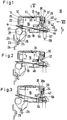
- FIGS. 1 to 4 each show an insight into an electrical switching device, preferably a residual current circuit breaker, the parts that are important for the invention being drawn and the parts that are less important for the invention have been omitted.
- the switching device or more precisely the residual current circuit breaker 10, has a housing 11, of which only the front part, that is to say the part which is opposite the fastening plane, can be seen.
- the housing 11 has an opening 13 in the front wall 12.
- a boomerang-shaped extension 20 is arranged perpendicularly thereto, the extension being integrally formed on the edge 19 via a connecting tab 21 running perpendicular to the guide plate.
- the extension 20 extends in the extension of the edge 22 on the left in the drawing in FIG. 1, which extends perpendicular to the front wall 12.
- a fixed contact piece 23 which is fastened to a contact piece holding rail 24 and which interacts with a movable contact piece 25 which is fastened to a contact lever 26 which is guided in a contact lever carrier 27, which is not illustrated in any more detail and is only indicated by outlines , wherein the contact lever 26 extends through the contact lever carrier 27 and projects beyond the contact lever carrier in the switched-on position on the opposite side facing the front wall, as indicated by the reference number 26 in this area.
- a lug 29, which runs parallel to the contact carrier axis of rotation 28 and against which the free end of the projection 20 comes to rest, is formed on the contact lever carrier 27, as can also be seen from FIG.
- the plate 16 has a recess 30, into which a compression spring 31 is inserted, which rests against a stationary stop 32 and acts continuously on the plate 16 in the direction of arrow P in the drawing to the left.
- the edge 33 lying opposite the edge 22 has a projection 34 projecting perpendicularly thereto, on which a web 35 is formed perpendicularly thereto; the web 35 runs perpendicular to the plate and perpendicular to the front front wall 12.
- the housing 11 On the right side in FIG. 1, the housing 11 has a recess 36, through which a recess 37 is formed, in which a test button is guided perpendicular to the front wall 12, the test button 38 having an arm 39 running perpendicular to the front wall 12, At the free end of an inwardly projecting nose 40 is formed, which engages behind a stop 41 on the housing 11, so that the movement of the test button in the direction of arrow F is limited.
- the test button 38 has a rod 42 running perpendicular to the front front wall 12.
- a spring support 43 is provided in a fixed position, which has a pin 44 which runs parallel to the axis of rotation 28 and around which a contact spring 45 is wound in the manner of a coil spring.
- One of the free legs namely the leg 46 of the contact spring engages over the inner region of the residual current circuit breaker and has a U-shaped end 47, with a transverse web 48 adjoining the leg 46 and an integrally formed on its free end, parallel and at an angle to the Leg 46 bent down to the contact lever 26 longitudinal web 49, the angle alpha being dimensioned such that the free end of the longitudinal web 49 continuously against the contact piece End of the contact lever 26 rests resiliently.
- an electrically conductive connection is obtained between the contact lever and the helical spring-like area 45a.
- the spring support 43 which is shown in a top view in FIG. 5, has a platform 50 which runs parallel to the front wall 12 and on which tabs 51 are formed which guide a lead wire 52 which runs parallel to the guide pin 44 on the platform.
- the pin 44 is formed on a holding wall 53 which runs perpendicular to the platform in the direction of the front wall, the holding wall 53 being aligned parallel to the plate 16.
- leg end 54 The end of the lead wire 52 adjacent to the holding wall 53 is bent parallel to it in a leg end 54, which leg end also rests on the platform and is held in place by means of a holding lug 55.
- the other end of the helical spring-shaped area 45a of the contact spring 45 is tangent to the pin 44 on the side opposite the platform 50, i.e. above the pin 44, bent away from the area 45a and bent parallel to the pin axis of the pin 44 as a movable contact element 56.
- the movable contact element 56 is, as can be seen in Figures 1 to 4, in the range of motion of the rod 42, so that when the test button 38 is pressed against the arrow direction F, it acts against the leg end 54 of the lead wire serving as a fixed contact piece 52 is pressed.
- the lead wire 52 is a leg of a resistor 57, the other leg 58 of which either has a phase conductor - if the rail 24 is in the line path of the neutral conductor of the residual current circuit breaker - or the neutral conductor if the rail 24 is in the line path a phase conductor is connected.
- Figure 1 shows the residual current circuit breaker in the state when the movable contact piece 25 just touches the fixed contact piece 23 when switching on.
- the free end of the extension 20 bears against the nose 29.
- Figure 2 shows the switch-on position, in which the contact lever in the drawing Figure 2 is to the left of the axis of rotation 28; it can be seen that the extension 20 is free of the nose 29.
- the contact lever 26 and, together with the contact lever carrier, also the nose 29 move into the off position, the nose 29 striking against the extension 20 and the extension and thus the plate 16 against the pressure of the compression spring 31 to the right presses so that the projection 34 comes under a shoulder 59 on the rod 42; the shoulder 59 is formed in the area of the pressing surface 38a of the test button 38 parallel to the rod 42 and in such a way that the shoulder 59 is located exactly above the movement path of the projection 34.
- Figure 4 shows the residual current circuit breaker in the off position; it can also be seen here that the paragraph 59 hits the extension 34 when the test button 38 is to be pressed down, so that the test button contact 54/56 cannot be closed.
- the plate 16 has at its upper and lower edges two guide lugs 60 and 61, which engage behind the guide plate 15 above and below, so that the plate 16 parallel to the upper and lower edges, which are also parallel run to the front wall, is movable.
- FIGS. 7 to 9 A further embodiment of the invention is shown in FIGS. 7 to 9.
- the same reference numbers are to be used for the same parts.
- the guide plate 15 Within the housing 11 is the guide plate 15, the axis of rotation 28 for the contact lever carrier 27, on which the contact lever 26 is attached, which carries the movable contact piece 25, which comes into contact with the fixed contact piece 23.
- a rotary plate 70 is rotatably articulated on the guide plate 15 via an axis 71.
- a tab 72 corresponding to the surface 18 is fastened perpendicularly to it; perpendicular to the connecting line between the tab 72 and the axis 71 is on the contact pieces 25 and 23 opposite edge of the rotating plate an extension 73 is formed, which has the same function as the extension 34.
- the residual current circuit breaker 10 has the test button 38 with the rod 42 and the paragraph 59th
- a hole 74 is provided, in which one end of a coupling lever 75 is suspended, whereas the other end is articulated on the contact lever carrier 27.
- the leg 46 of the spring 45 which is only partially shown, is designed and connected to the movable contact piece as described above.
- FIG. 7 shows the switching device in the contact contact position, that is to say in the position in which the movable contact piece 25 just touches the fixed contact piece 23 when it is switched on. During the further switch-on process, only the position of the contact lever 26 changes, while the position of the rotating plate 70 is unchanged.
- test button 38 can be pressed, so that the leg 56 of the contact spring 45 can be connected to the leg 54 of the lead wire 52 with the resistor 57 and a circuit between the contact lever 26 and a corresponding conductor is closed.
- the extension 73 comes under the paragraph 59 of the test button 38, so that the extension 73 hampers or prevents the test button 38 from being pushed in completely.
- both the sliding plate 16 and the rotating plate 70 have a tab 17 and 72 perpendicular to it, respectively.
- These tabs can be coated with different colors, for example the surface 17 to the left of the center line 17a can be coated in green and the surface to the right of it can be coated in red, so that the red-coated surface is visible through the opening 13 in the switched-on state, whereas the green surface in the switched-off state is recognizable.
- the tab 72 can also be coated, so that the opening 13 can signal red in the on state and green in the off state.
Landscapes
- Breakers (AREA)
- Switch Cases, Indication, And Locking (AREA)
- Driving Mechanisms And Operating Circuits Of Arc-Extinguishing High-Tension Switches (AREA)
Applications Claiming Priority (2)
| Application Number | Priority Date | Filing Date | Title |
|---|---|---|---|
| DE4211915A DE4211915C2 (de) | 1992-04-09 | 1992-04-09 | Prüftastenanordnung für einen Fehlerstrom- oder Differenzstromschutzschalter |
| DE4211915 | 1992-04-09 |
Publications (2)
| Publication Number | Publication Date |
|---|---|
| EP0565008A1 true EP0565008A1 (fr) | 1993-10-13 |
| EP0565008B1 EP0565008B1 (fr) | 1996-05-22 |
Family
ID=6456451
Family Applications (1)
| Application Number | Title | Priority Date | Filing Date |
|---|---|---|---|
| EP93105552A Expired - Lifetime EP0565008B1 (fr) | 1992-04-09 | 1993-04-03 | Dispositif à bouton de contrÔle pour disjoncteur pour courant de défaut ou à courant différentiel |
Country Status (5)
| Country | Link |
|---|---|
| EP (1) | EP0565008B1 (fr) |
| CN (1) | CN1031737C (fr) |
| AT (1) | ATE138496T1 (fr) |
| DE (2) | DE4211915C2 (fr) |
| ES (1) | ES2090752T3 (fr) |
Cited By (1)
| Publication number | Priority date | Publication date | Assignee | Title |
|---|---|---|---|---|
| CN120294552A (zh) * | 2025-04-09 | 2025-07-11 | 江苏埃尔奇电气科技有限公司 | 一种断路器生产检测装置 |
Families Citing this family (2)
| Publication number | Priority date | Publication date | Assignee | Title |
|---|---|---|---|---|
| CN105510818B (zh) * | 2015-12-30 | 2019-02-05 | 三信国际电器上海有限公司 | 断路器及其试验装置和方法 |
| CN109507573B (zh) * | 2018-07-13 | 2021-06-01 | 西安益翔航电科技有限公司 | 一种断路器高低温性能测试装置 |
Citations (3)
| Publication number | Priority date | Publication date | Assignee | Title |
|---|---|---|---|---|
| FR2437692A1 (fr) * | 1978-09-28 | 1980-04-25 | Merlin Gerin | Dispositif de protection differentielle a bloc differentiel accouple au bloc disjoncteur |
| FR2609209A1 (fr) * | 1986-12-29 | 1988-07-01 | Merlin Gerin | Interrupteur differentiel bipolaire a indicateur de defaut |
| EP0451481A2 (fr) * | 1990-04-11 | 1991-10-16 | Felten & Guilleaume Energietechnik AG | Dispositif pour tester un disjoncteur de défaut à la terre |
Family Cites Families (3)
| Publication number | Priority date | Publication date | Assignee | Title |
|---|---|---|---|---|
| DE1059094B (de) * | 1957-10-04 | 1959-06-11 | Voigt & Haeffner Ag | Mehrpoliger Selbstschalter, insbesondere Installations-Selbstschalter |
| DE1152745B (de) * | 1961-11-15 | 1963-08-14 | Emil Quermann | Pruefeinrichtung fuer Schutzschalter |
| FR2584531B1 (fr) * | 1985-07-05 | 1989-01-13 | Telemecanique Electrique | Limiteur de courant muni d'un element de visualisation |
-
1992
- 1992-04-09 DE DE4211915A patent/DE4211915C2/de not_active Expired - Fee Related
-
1993
- 1993-04-03 AT AT93105552T patent/ATE138496T1/de not_active IP Right Cessation
- 1993-04-03 EP EP93105552A patent/EP0565008B1/fr not_active Expired - Lifetime
- 1993-04-03 ES ES93105552T patent/ES2090752T3/es not_active Expired - Lifetime
- 1993-04-03 DE DE59302648T patent/DE59302648D1/de not_active Expired - Fee Related
- 1993-04-08 CN CN93104024A patent/CN1031737C/zh not_active Expired - Fee Related
Patent Citations (3)
| Publication number | Priority date | Publication date | Assignee | Title |
|---|---|---|---|---|
| FR2437692A1 (fr) * | 1978-09-28 | 1980-04-25 | Merlin Gerin | Dispositif de protection differentielle a bloc differentiel accouple au bloc disjoncteur |
| FR2609209A1 (fr) * | 1986-12-29 | 1988-07-01 | Merlin Gerin | Interrupteur differentiel bipolaire a indicateur de defaut |
| EP0451481A2 (fr) * | 1990-04-11 | 1991-10-16 | Felten & Guilleaume Energietechnik AG | Dispositif pour tester un disjoncteur de défaut à la terre |
Cited By (1)
| Publication number | Priority date | Publication date | Assignee | Title |
|---|---|---|---|---|
| CN120294552A (zh) * | 2025-04-09 | 2025-07-11 | 江苏埃尔奇电气科技有限公司 | 一种断路器生产检测装置 |
Also Published As
| Publication number | Publication date |
|---|---|
| ATE138496T1 (de) | 1996-06-15 |
| DE4211915A1 (de) | 1993-10-14 |
| DE4211915C2 (de) | 1995-03-16 |
| CN1031737C (zh) | 1996-05-01 |
| ES2090752T3 (es) | 1996-10-16 |
| DE59302648D1 (de) | 1996-06-27 |
| EP0565008B1 (fr) | 1996-05-22 |
| CN1080430A (zh) | 1994-01-05 |
Similar Documents
| Publication | Publication Date | Title |
|---|---|---|
| EP0436881B1 (fr) | Dérivateur de surtensions | |
| EP0905839A1 (fr) | Dérivatuer de surtensions enfichable | |
| EP0222181A1 (fr) | Disjoncteur de surintensité | |
| DE9004196U1 (de) | Prüfeinrichtung für Fehlerstromschutzschalter | |
| DE8904063U1 (de) | Druckknopfbetätigter Überstromschutzschalter | |
| EP0199119B1 (fr) | Relais électromagnétique | |
| DE3516217C2 (fr) | ||
| DE69507272T2 (de) | Anordnung zur Befestigung eines elektrischen Gerätes an einer Tragschiene | |
| DE2722279C3 (de) | Sicherungsschalter | |
| EP0565008B1 (fr) | Dispositif à bouton de contrÔle pour disjoncteur pour courant de défaut ou à courant différentiel | |
| EP0238960B1 (fr) | Appareil électrique d'installation | |
| EP0243648B1 (fr) | Disjoncteur électrique | |
| DE19814397C1 (de) | Anordnung zur Schaltstellungsanzeige und Abbrandanzeige bei einem elektrischen Schaltgerät | |
| DE19619700C2 (de) | Schalter zur Verwendung in elektronischen Vorrichtungen | |
| DE2732723C2 (de) | Elektrische Schaltvorrichtung | |
| EP0068483A1 (fr) | Commutateur électromécanique pour appareils téléphoniques | |
| DE3877262T2 (de) | Testeinheit fuer elektrischen differentialschutzapparat und apparate mit dieser einheit. | |
| DE19934542C1 (de) | Schaltersicherungseinheit mit Halterverriegelung | |
| DE2705330A1 (de) | Elektrischer schalter, insbesondere motorschutzschalter | |
| EP1030336A2 (fr) | Contacteur d'installation électrique | |
| DE19527045C2 (de) | Kontaktanordnung für ein elektrisches Schaltgerät | |
| EP1069583A2 (fr) | Mécanisme de commutation pour appareillage électrique de commutation, en particulier pour un disjoncteur | |
| DE2558620C2 (de) | Elektrischer Schalter | |
| DE3243323A1 (de) | Elektrischer schalter | |
| DE3126958A1 (de) | Schutzschalter, insbesondere sprungmagnetschutzschalter |
Legal Events
| Date | Code | Title | Description |
|---|---|---|---|
| PUAI | Public reference made under article 153(3) epc to a published international application that has entered the european phase |
Free format text: ORIGINAL CODE: 0009012 |
|
| AK | Designated contracting states |
Kind code of ref document: A1 Designated state(s): AT BE CH DE ES FR GB IT LI PT |
|
| 17P | Request for examination filed |
Effective date: 19931029 |
|
| 17Q | First examination report despatched |
Effective date: 19951031 |
|
| GRAH | Despatch of communication of intention to grant a patent |
Free format text: ORIGINAL CODE: EPIDOS IGRA |
|
| GRAA | (expected) grant |
Free format text: ORIGINAL CODE: 0009210 |
|
| AK | Designated contracting states |
Kind code of ref document: B1 Designated state(s): AT BE CH DE ES FR GB IT LI PT |
|
| REF | Corresponds to: |
Ref document number: 138496 Country of ref document: AT Date of ref document: 19960615 Kind code of ref document: T |
|
| REF | Corresponds to: |
Ref document number: 59302648 Country of ref document: DE Date of ref document: 19960627 |
|
| ITF | It: translation for a ep patent filed | ||
| ET | Fr: translation filed | ||
| GBT | Gb: translation of ep patent filed (gb section 77(6)(a)/1977) |
Effective date: 19960624 |
|
| SC4A | Pt: translation is available |
Free format text: 960626 AVAILABILITY OF NATIONAL TRANSLATION |
|
| REG | Reference to a national code |
Ref country code: ES Ref legal event code: FG2A Ref document number: 2090752 Country of ref document: ES Kind code of ref document: T3 |
|
| REG | Reference to a national code |
Ref country code: ES Ref legal event code: FG2A Ref document number: 2090752 Country of ref document: ES Kind code of ref document: T3 |
|
| PLBE | No opposition filed within time limit |
Free format text: ORIGINAL CODE: 0009261 |
|
| 26N | No opposition filed | ||
| PGFP | Annual fee paid to national office [announced via postgrant information from national office to epo] |
Ref country code: BE Payment date: 19980212 Year of fee payment: 6 |
|
| PGFP | Annual fee paid to national office [announced via postgrant information from national office to epo] |
Ref country code: PT Payment date: 19980219 Year of fee payment: 6 |
|
| PGFP | Annual fee paid to national office [announced via postgrant information from national office to epo] |
Ref country code: GB Payment date: 19980223 Year of fee payment: 6 Ref country code: CH Payment date: 19980223 Year of fee payment: 6 |
|
| PGFP | Annual fee paid to national office [announced via postgrant information from national office to epo] |
Ref country code: ES Payment date: 19980429 Year of fee payment: 6 |
|
| PGFP | Annual fee paid to national office [announced via postgrant information from national office to epo] |
Ref country code: DE Payment date: 19990128 Year of fee payment: 7 |
|
| PGFP | Annual fee paid to national office [announced via postgrant information from national office to epo] |
Ref country code: AT Payment date: 19990216 Year of fee payment: 7 |
|
| PGFP | Annual fee paid to national office [announced via postgrant information from national office to epo] |
Ref country code: FR Payment date: 19990218 Year of fee payment: 7 |
|
| PG25 | Lapsed in a contracting state [announced via postgrant information from national office to epo] |
Ref country code: GB Free format text: LAPSE BECAUSE OF NON-PAYMENT OF DUE FEES Effective date: 19990403 |
|
| PG25 | Lapsed in a contracting state [announced via postgrant information from national office to epo] |
Ref country code: ES Free format text: THE PATENT HAS BEEN ANNULLED BY A DECISION OF A NATIONAL AUTHORITY Effective date: 19990405 |
|
| PG25 | Lapsed in a contracting state [announced via postgrant information from national office to epo] |
Ref country code: LI Free format text: LAPSE BECAUSE OF NON-PAYMENT OF DUE FEES Effective date: 19990430 Ref country code: CH Free format text: LAPSE BECAUSE OF NON-PAYMENT OF DUE FEES Effective date: 19990430 Ref country code: BE Free format text: LAPSE BECAUSE OF NON-PAYMENT OF DUE FEES Effective date: 19990430 |
|
| BERE | Be: lapsed |
Owner name: ABB PATENT G.M.B.H. Effective date: 19990430 |
|
| PG25 | Lapsed in a contracting state [announced via postgrant information from national office to epo] |
Ref country code: PT Free format text: LAPSE BECAUSE OF NON-PAYMENT OF DUE FEES Effective date: 19991031 |
|
| GBPC | Gb: european patent ceased through non-payment of renewal fee |
Effective date: 19990403 |
|
| REG | Reference to a national code |
Ref country code: CH Ref legal event code: PL |
|
| REG | Reference to a national code |
Ref country code: PT Ref legal event code: MM4A Free format text: LAPSE DUE TO NON-PAYMENT OF FEES Effective date: 19991031 |
|
| PG25 | Lapsed in a contracting state [announced via postgrant information from national office to epo] |
Ref country code: AT Free format text: LAPSE BECAUSE OF NON-PAYMENT OF DUE FEES Effective date: 20000403 |
|
| PG25 | Lapsed in a contracting state [announced via postgrant information from national office to epo] |
Ref country code: FR Free format text: LAPSE BECAUSE OF NON-PAYMENT OF DUE FEES Effective date: 20001229 |
|
| PG25 | Lapsed in a contracting state [announced via postgrant information from national office to epo] |
Ref country code: DE Free format text: LAPSE BECAUSE OF NON-PAYMENT OF DUE FEES Effective date: 20010201 |
|
| REG | Reference to a national code |
Ref country code: FR Ref legal event code: ST |
|
| REG | Reference to a national code |
Ref country code: ES Ref legal event code: FD2A Effective date: 20010604 |
|
| PG25 | Lapsed in a contracting state [announced via postgrant information from national office to epo] |
Ref country code: IT Free format text: LAPSE BECAUSE OF NON-PAYMENT OF DUE FEES;WARNING: LAPSES OF ITALIAN PATENTS WITH EFFECTIVE DATE BEFORE 2007 MAY HAVE OCCURRED AT ANY TIME BEFORE 2007. THE CORRECT EFFECTIVE DATE MAY BE DIFFERENT FROM THE ONE RECORDED. Effective date: 20050403 |