EP0565142B1 - Catalyseur comprenant au moins un capteur de température - Google Patents
Catalyseur comprenant au moins un capteur de température Download PDFInfo
- Publication number
- EP0565142B1 EP0565142B1 EP93111141A EP93111141A EP0565142B1 EP 0565142 B1 EP0565142 B1 EP 0565142B1 EP 93111141 A EP93111141 A EP 93111141A EP 93111141 A EP93111141 A EP 93111141A EP 0565142 B1 EP0565142 B1 EP 0565142B1
- Authority
- EP
- European Patent Office
- Prior art keywords
- catalytic converter
- temperature sensor
- temperature
- converter according
- cross
- Prior art date
- Legal status (The legal status is an assumption and is not a legal conclusion. Google has not performed a legal analysis and makes no representation as to the accuracy of the status listed.)
- Expired - Lifetime
Links
Images


Classifications
-
- F—MECHANICAL ENGINEERING; LIGHTING; HEATING; WEAPONS; BLASTING
- F02—COMBUSTION ENGINES; HOT-GAS OR COMBUSTION-PRODUCT ENGINE PLANTS
- F02D—CONTROLLING COMBUSTION ENGINES
- F02D41/00—Electrical control of supply of combustible mixture or its constituents
- F02D41/02—Circuit arrangements for generating control signals
- F02D41/14—Introducing closed-loop corrections
- F02D41/1438—Introducing closed-loop corrections using means for determining characteristics of the combustion gases; Sensors therefor
- F02D41/1439—Introducing closed-loop corrections using means for determining characteristics of the combustion gases; Sensors therefor characterised by the position of the sensor
- F02D41/1441—Plural sensors
-
- F—MECHANICAL ENGINEERING; LIGHTING; HEATING; WEAPONS; BLASTING
- F01—MACHINES OR ENGINES IN GENERAL; ENGINE PLANTS IN GENERAL; STEAM ENGINES
- F01N—GAS-FLOW SILENCERS OR EXHAUST APPARATUS FOR MACHINES OR ENGINES IN GENERAL; GAS-FLOW SILENCERS OR EXHAUST APPARATUS FOR INTERNAL-COMBUSTION ENGINES
- F01N11/00—Monitoring or diagnostic devices for exhaust-gas treatment apparatus
- F01N11/002—Monitoring or diagnostic devices for exhaust-gas treatment apparatus the diagnostic devices measuring or estimating temperature or pressure in, or downstream of the exhaust apparatus
-
- F—MECHANICAL ENGINEERING; LIGHTING; HEATING; WEAPONS; BLASTING
- F01—MACHINES OR ENGINES IN GENERAL; ENGINE PLANTS IN GENERAL; STEAM ENGINES
- F01N—GAS-FLOW SILENCERS OR EXHAUST APPARATUS FOR MACHINES OR ENGINES IN GENERAL; GAS-FLOW SILENCERS OR EXHAUST APPARATUS FOR INTERNAL-COMBUSTION ENGINES
- F01N13/00—Exhaust or silencing apparatus characterised by constructional features
- F01N13/008—Mounting or arrangement of exhaust sensors in or on exhaust apparatus
-
- F—MECHANICAL ENGINEERING; LIGHTING; HEATING; WEAPONS; BLASTING
- F01—MACHINES OR ENGINES IN GENERAL; ENGINE PLANTS IN GENERAL; STEAM ENGINES
- F01N—GAS-FLOW SILENCERS OR EXHAUST APPARATUS FOR MACHINES OR ENGINES IN GENERAL; GAS-FLOW SILENCERS OR EXHAUST APPARATUS FOR INTERNAL-COMBUSTION ENGINES
- F01N3/00—Exhaust or silencing apparatus having means for purifying, rendering innocuous, or otherwise treating exhaust
- F01N3/08—Exhaust or silencing apparatus having means for purifying, rendering innocuous, or otherwise treating exhaust for rendering innocuous
- F01N3/10—Exhaust or silencing apparatus having means for purifying, rendering innocuous, or otherwise treating exhaust for rendering innocuous by thermal or catalytic conversion of noxious components of exhaust
- F01N3/18—Exhaust or silencing apparatus having means for purifying, rendering innocuous, or otherwise treating exhaust for rendering innocuous by thermal or catalytic conversion of noxious components of exhaust characterised by methods of operation; Control
- F01N3/20—Exhaust or silencing apparatus having means for purifying, rendering innocuous, or otherwise treating exhaust for rendering innocuous by thermal or catalytic conversion of noxious components of exhaust characterised by methods of operation; Control specially adapted for catalytic conversion
- F01N3/2006—Periodically heating or cooling catalytic reactors, e.g. at cold starting or overheating
- F01N3/2013—Periodically heating or cooling catalytic reactors, e.g. at cold starting or overheating using electric or magnetic heating means
-
- F—MECHANICAL ENGINEERING; LIGHTING; HEATING; WEAPONS; BLASTING
- F01—MACHINES OR ENGINES IN GENERAL; ENGINE PLANTS IN GENERAL; STEAM ENGINES
- F01N—GAS-FLOW SILENCERS OR EXHAUST APPARATUS FOR MACHINES OR ENGINES IN GENERAL; GAS-FLOW SILENCERS OR EXHAUST APPARATUS FOR INTERNAL-COMBUSTION ENGINES
- F01N3/00—Exhaust or silencing apparatus having means for purifying, rendering innocuous, or otherwise treating exhaust
- F01N3/08—Exhaust or silencing apparatus having means for purifying, rendering innocuous, or otherwise treating exhaust for rendering innocuous
- F01N3/10—Exhaust or silencing apparatus having means for purifying, rendering innocuous, or otherwise treating exhaust for rendering innocuous by thermal or catalytic conversion of noxious components of exhaust
- F01N3/24—Exhaust or silencing apparatus having means for purifying, rendering innocuous, or otherwise treating exhaust for rendering innocuous by thermal or catalytic conversion of noxious components of exhaust characterised by constructional aspects of converting apparatus
- F01N3/28—Construction of catalytic reactors
- F01N3/2803—Construction of catalytic reactors characterised by structure, by material or by manufacturing of catalyst support
- F01N3/2807—Metal other than sintered metal
- F01N3/281—Metallic honeycomb monoliths made of stacked or rolled sheets, foils or plates
-
- F—MECHANICAL ENGINEERING; LIGHTING; HEATING; WEAPONS; BLASTING
- F01—MACHINES OR ENGINES IN GENERAL; ENGINE PLANTS IN GENERAL; STEAM ENGINES
- F01N—GAS-FLOW SILENCERS OR EXHAUST APPARATUS FOR MACHINES OR ENGINES IN GENERAL; GAS-FLOW SILENCERS OR EXHAUST APPARATUS FOR INTERNAL-COMBUSTION ENGINES
- F01N2550/00—Monitoring or diagnosing the deterioration of exhaust systems
-
- F—MECHANICAL ENGINEERING; LIGHTING; HEATING; WEAPONS; BLASTING
- F01—MACHINES OR ENGINES IN GENERAL; ENGINE PLANTS IN GENERAL; STEAM ENGINES
- F01N—GAS-FLOW SILENCERS OR EXHAUST APPARATUS FOR MACHINES OR ENGINES IN GENERAL; GAS-FLOW SILENCERS OR EXHAUST APPARATUS FOR INTERNAL-COMBUSTION ENGINES
- F01N2550/00—Monitoring or diagnosing the deterioration of exhaust systems
- F01N2550/02—Catalytic activity of catalytic converters
-
- F—MECHANICAL ENGINEERING; LIGHTING; HEATING; WEAPONS; BLASTING
- F02—COMBUSTION ENGINES; HOT-GAS OR COMBUSTION-PRODUCT ENGINE PLANTS
- F02B—INTERNAL-COMBUSTION PISTON ENGINES; COMBUSTION ENGINES IN GENERAL
- F02B1/00—Engines characterised by fuel-air mixture compression
- F02B1/02—Engines characterised by fuel-air mixture compression with positive ignition
- F02B1/04—Engines characterised by fuel-air mixture compression with positive ignition with fuel-air mixture admission into cylinder
-
- Y—GENERAL TAGGING OF NEW TECHNOLOGICAL DEVELOPMENTS; GENERAL TAGGING OF CROSS-SECTIONAL TECHNOLOGIES SPANNING OVER SEVERAL SECTIONS OF THE IPC; TECHNICAL SUBJECTS COVERED BY FORMER USPC CROSS-REFERENCE ART COLLECTIONS [XRACs] AND DIGESTS
- Y02—TECHNOLOGIES OR APPLICATIONS FOR MITIGATION OR ADAPTATION AGAINST CLIMATE CHANGE
- Y02A—TECHNOLOGIES FOR ADAPTATION TO CLIMATE CHANGE
- Y02A50/00—TECHNOLOGIES FOR ADAPTATION TO CLIMATE CHANGE in human health protection, e.g. against extreme weather
- Y02A50/20—Air quality improvement or preservation, e.g. vehicle emission control or emission reduction by using catalytic converters
-
- Y—GENERAL TAGGING OF NEW TECHNOLOGICAL DEVELOPMENTS; GENERAL TAGGING OF CROSS-SECTIONAL TECHNOLOGIES SPANNING OVER SEVERAL SECTIONS OF THE IPC; TECHNICAL SUBJECTS COVERED BY FORMER USPC CROSS-REFERENCE ART COLLECTIONS [XRACs] AND DIGESTS
- Y02—TECHNOLOGIES OR APPLICATIONS FOR MITIGATION OR ADAPTATION AGAINST CLIMATE CHANGE
- Y02T—CLIMATE CHANGE MITIGATION TECHNOLOGIES RELATED TO TRANSPORTATION
- Y02T10/00—Road transport of goods or passengers
- Y02T10/10—Internal combustion engine [ICE] based vehicles
- Y02T10/12—Improving ICE efficiencies
-
- Y—GENERAL TAGGING OF NEW TECHNOLOGICAL DEVELOPMENTS; GENERAL TAGGING OF CROSS-SECTIONAL TECHNOLOGIES SPANNING OVER SEVERAL SECTIONS OF THE IPC; TECHNICAL SUBJECTS COVERED BY FORMER USPC CROSS-REFERENCE ART COLLECTIONS [XRACs] AND DIGESTS
- Y02—TECHNOLOGIES OR APPLICATIONS FOR MITIGATION OR ADAPTATION AGAINST CLIMATE CHANGE
- Y02T—CLIMATE CHANGE MITIGATION TECHNOLOGIES RELATED TO TRANSPORTATION
- Y02T10/00—Road transport of goods or passengers
- Y02T10/10—Internal combustion engine [ICE] based vehicles
- Y02T10/40—Engine management systems
Definitions
- the present invention relates to a catalyst with at least one temperature sensor.
- a catalytic converter In accordance with the increasingly stringent environmental protection regulations in many countries, many internal combustion engines, in particular in motor vehicles, are now equipped with a catalytic converter. Such a catalytic converter is flowed through by the exhaust gas and catalytically converts pollutants in the exhaust gas into harmless substances in its catalytically active volume, which has a large surface that comes into contact with the exhaust gas.
- Many different designs are known as carrier bodies for catalytically active material, partly made of ceramic and partly made of metal. They are generally honeycomb-like bodies which have a multiplicity of channels through which the exhaust gas flows.
- Metallic catalysts are generally layered from structured sheets, spirally wound, or otherwise devoured. Such forms are described, for example, in EP-B-0 223 058, EP-B-0 245 737 or EP-B-0 245 738.
- Such heatable catalysts are described, for example, in WO 89/10470.
- WO-89/10471 discloses a heatable catalyst body with layered, wound structured sheets, in which a heating element is integrated in its foremost part in a cross-sectional area near its end faces, which is formed by the sheet layers.
- These sheet metal layers are, additionally or alternatively, temperature sensors which carry out a temperature measurement via the resistance. Since the sheet metal layers extend over the respective catalytic converter disc, the temperature sensor measures the temperature of the catalytic converter disc over its entire cross-sectional area. Because of the overall low resistance of such a heatable honeycomb body, the measurement accuracy is not particularly high, particularly in the case of transient processes. The monitoring of a catalytic converter with such a resistance measurement over the whole body is only meaningful to a limited extent.
- the object of the invention is to strengthen a measuring system for the most accurate possible monitoring of the function of the catalyst in operation with the least possible effort and low susceptibility to malfunction, the temperature being measured integrally over a representative part of at least one cross-sectional area.
- the invention is based on the idea that the conversion of pollutants in the catalytic converter is an exothermic reaction, so that energy is released.
- This effect is to be used in the present invention to monitor the functionality of the catalytic converter and, if possible, to determine other information.
- the temperature is not measured selectively, but rather integrally over an approximately representative part of the cross-sectional area. This increases the accuracy of the monitoring.
- a measurement is considered representative which contains information both from the edge areas of the flow and from the central areas.
- a cross-sectional area is a disk from the exhaust system, which lies approximately in a cross-sectional plane, in which the measurement is carried out.
- the temperature sensor runs parallel to a sheet metal layer of the catalyst, this is preferably inserted or integrated into the sheet metal layer.
- Linear temperature sensors are suitable for integral measurements.
- sensors with a temperature-dependent resistance preferably in the form of a wire, come into consideration.
- temperature measurements are among the most precise and well-controlled measurements in technology and are therefore suitable for the present application. They also respond to relatively small and quick changes.
- At least one temperature measuring point is preferably arranged within the catalyst itself.
- electrical feedthroughs and connections are already present in this case, so that this additional instrumentation does not unduly increase the wiring effort of the exhaust system.
- a temperature measuring point integrated in the catalytic converter has a temperature in the front end area measures proportional to the temperature of the inflowing exhaust gas, while a temperature measuring point in the outflow region of the catalyst measures a temperature proportional to the temperature of the outflowing exhaust gases.
- the temperature sensors so that the exhaust gas essentially flows around them and therefore measure the exhaust gas temperature, but one can also arrange the temperature measuring points in such a way that they are in good thermal contact with the catalyst material or the support material of the catalyst.
- the temperature measuring points There are good reasons for both options, which must be taken into account when selecting the measuring system, taking into account the main operating temperatures and the geometry of the catalyst arrangements. It may be advantageous, for example, to measure the gas temperature in the front area of the catalyst and the temperature of the support material in the rear area. According to the current understanding of the heat transfer processes, the energy released in the catalytic conversion is first transferred to the catalyst support material and from there to the exhaust gas flowing out again.
- the energy generated in the catalytic converter is so high that significant temperature differences are easy to measure.
- a specially designed catalyst which has at least one integrated temperature sensor in at least one cross-sectional area according to claim 1, which integrally measures the temperature over an approximately representative part of the cross-sectional area. It is suitable for systems in which such temperature measurements are required.
- heatable catalysts can also be equipped in this way, even if they do not have operational monitoring are provided. Special embodiments of the integrated temperature sensors are also described below with reference to the drawing.
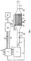
- FIG. 1 schematically shows an internal combustion engine 1 with an electronic motor control 2, which receives information from outside via measured value feed lines 3 and then controls the motor 1 via motor feed lines 4. Exhaust gases pass from the engine in the direction of the arrow into an exhaust gas line 5, in which a lambda probe 6 is arranged, which in turn is connected to the engine control 2 via a measured value line 7.
- a catalytic converter 8 is arranged in the exhaust gas line, to which an exhaust gas outlet line 9 connects.
- the catalytic converter 8 can consist of one or more individual disks and, of course, the exhaust system can also be constructed in multiple strands, but neither of these plays a decisive role for the present invention.
- the catalytic converter 8 can also be electrically heatable at least in partial areas and have corresponding electrical connections 17 and 18.
- At least two temperature sensors should be arranged in the exhaust system between which at least part of the catalytically active volume is located.
- the front temperature sensor namely the temperature sensor TF1 in the front end region of the catalytic converter 8 and the temperature sensor TF1 'in the exhaust gas line 5.
- the rear temperature sensor namely one in the rear end region of the catalytic converter 8 integrated temperature sensor TF2 and a temperature sensor TF2 'arranged in the exhaust gas outlet line 9.
- Which of the respective alternatives should be advantageously combined depends on the geometrical conditions and other factors. It is particularly important that a substantial part of the catalytic reactions take place between the measuring points.
- the temperature measurement values are fed to monitoring electronics 10 via the measuring lines 13 and 14.
- This ad can e.g. B. in the form of signal lamps or display instruments.
- FIG. 2 illustrates a possible embodiment of the invention.
- Fig. 2 is a partially schematic section through the catalyst 8 in the plane of a temperature sensor TF.
- 2 is an embodiment of an electrically heatable metallic catalyst carrier known per se from WO 89/10470, which consists of sheet metal layers which are intertwined in opposite directions and is thus divided in its cross-sectional area by insulating layers is that an electrical resistance and current path suitable for heating is created.
- This catalytic converter 8 is constructed from alternating layers of corrugated 21 and smooth metal sheets 22 and is provided in its interior with insulating layers that are only schematically indicated here and run inwards in a spiral shape.
- the sheet metal layers are surrounded by a jacket which consists of two half-shells 23, 24 which are electrically separated from one another by insulating sections 25, 26.
- the jacket half-shells 23, 24 are provided with electrical connections 27, 28 for electrical heating.
- a temperature sensor TF which in the present exemplary embodiment contains a wire whose resistance changes with the temperature, now runs inside this catalytic converter 8 parallel to the individual sheet metal layers.
- the resistance wire is laid in a U-shape on the inside, that is to say it consists of a forward and return line connected at the end, as is illustrated in FIGS. 3 and 4.
- the temperature sensor TF is guided on one side through the jacket 24 to the outside and there has connections 29 for the measuring lines.
- the principle shown here for laying a temperature sensor TF in a catalytic converter 8 is only one exemplary embodiment. Many other possibilities for differently constructed catalysts are conceivable, in particular the spiral winding of a temperature sensor.
- FIG. 3 shows a longitudinal section through the end of the temperature sensor TF for illustration, and in FIG. 4 a cross section along the line IV-IV in FIG. 3 is shown.
- the thermal sensor has a jacket 31, which can consist, for example, of Inconel or another high-temperature-resistant steel with chromium and / or aluminum components. Depending on the requirements, the jacket 31 can also consist of the same material as the sheets of the catalytic converter 8 Soldering between temperature sensor TF and sheets 21, 22 or the jacket 24 is possible without any problems.
- a wire 33, 34 is laid in a U-shape, the wire being able to consist, for example, of nickel or another material which has a resistance that is strongly dependent on the temperature.
- An insulating layer 32 e.g. B. from magnesium oxide powder, prevents contacts between the two lines 33, 34 of the resistance wire to each other and to the sheath 31 in a known manner.
- FIG. 5 shows, by way of illustration, a small section of a corrugated or, in the present case, folded sheet metal, as is used to build up catalyst carrier bodies.
- the temperature sensor TF is approximately halfway up the corrugation, then this measures mainly the temperature of the gas flowing past and not to the same extent the temperature of the structure itself.
- soldering to the adjacent next smooth sheet can be achieved by the temperature sensor TF mainly measuring the temperature of the support structure.
- a flexible design depending on the requirements is therefore possible.
- the present invention is particularly suitable for advanced integral diagnostic and monitoring systems in motor vehicles that have internal combustion engines with electronic injection and are equipped with regulated catalysts.
- the invention can be used particularly advantageously in conjunction with electrically heatable catalysts.
Landscapes
- Engineering & Computer Science (AREA)
- Chemical & Material Sciences (AREA)
- Chemical Kinetics & Catalysis (AREA)
- Combustion & Propulsion (AREA)
- Mechanical Engineering (AREA)
- General Engineering & Computer Science (AREA)
- Health & Medical Sciences (AREA)
- Toxicology (AREA)
- Analytical Chemistry (AREA)
- Exhaust Gas After Treatment (AREA)
- Exhaust Gas Treatment By Means Of Catalyst (AREA)
- Details Of Garments (AREA)
Claims (7)
- Catalyseur (8) équipé de couches de tôles et comportant un capteur de température et dans lequel dans au moins une partie de la section transversale est intégré au moins un capteur de température (TF; TF1; TF2), qui s'étend dans une direction radiale aussi bien sur la zone marginale que sur la zone centrale d'une partie de la section transversale, caractérisé en ce que le capteur de température est agencé sous la forme d'un capteur de température de forme linéaire et est parallèle à une couche de tôle du catalyseur, et de préférence est inséré ou intégré dans cette couche de tôle.
- Catalyseur selon la revendication 1, caractérisé en ce que le catalyseur (8) peut être chauffé électriquement au moins dans des zones partielles et qu'au moins un capteur de température (TF;TF1) est disposé à proximité de la zone partielle pouvant être chauffée.
- Catalyseur selon la revendication 1 ou 2, caractérisé en ce que le catalyseur (8) est constitué par des tôles (21,22) disposées suivant des couches et au moins partiellement structurées et qui sont empilées, enroulées ou imbriquées les unes dans les autres, le au moins un capteur de température (TF;TF1;TF2) étant intégré dans l'une des couches structurées de tôle (21), et de préférence est inséré dans une fente (51) qui s'étend approximativement transversalement par rapport à la structure.
- Catalyseur selon l'une des revendications précédentes, caractérisé en ce que le au moins un capteur de température (TF) contient un fil (33,34) possédant une résistance ohmique qui dépend de la température, et qui est entouré par une enveloppe métallique (31) et est isolé électriquement de cette dernière par une couche isolante (32).
- Catalyseur selon la revendication 4, caractérisé en ce que l'enveloppe (31) du capteur de température (TF) est réalisée en inconel ou en un acier contenant du chrome et/ou de l'aluminium et très résistant aux hautes températures.
- Catalyseur selon l'une des revendications précédentes, caractérisé en ce qu'au moins deux capteurs de température (TF,TF2) sont présents dans au moins deux parties de la section transversale.
- Catalyseur selon l'une des revendications précédentes, caractérisé en ce qu'au moins un capteur de température (TF1,TF2) est disposé à proximité d'une surface frontale du catalyseur (8).
Applications Claiming Priority (3)
| Application Number | Priority Date | Filing Date | Title |
|---|---|---|---|
| DE4008779 | 1990-03-19 | ||
| DE4008779 | 1990-03-19 | ||
| EP91906416A EP0521052B1 (fr) | 1990-03-19 | 1991-03-18 | Procede et dispositif permettant de surveiller le fonctionnement d'un catalyseur dans un moteur a combustion interne |
Related Parent Applications (2)
| Application Number | Title | Priority Date | Filing Date |
|---|---|---|---|
| EP91906416A Division EP0521052B1 (fr) | 1990-03-19 | 1991-03-18 | Procede et dispositif permettant de surveiller le fonctionnement d'un catalyseur dans un moteur a combustion interne |
| EP91906416.2 Division | 1991-03-18 |
Publications (3)
| Publication Number | Publication Date |
|---|---|
| EP0565142A2 EP0565142A2 (fr) | 1993-10-13 |
| EP0565142A3 EP0565142A3 (en) | 1993-11-24 |
| EP0565142B1 true EP0565142B1 (fr) | 1996-02-28 |
Family
ID=6402555
Family Applications (2)
| Application Number | Title | Priority Date | Filing Date |
|---|---|---|---|
| EP91906416A Expired - Lifetime EP0521052B1 (fr) | 1990-03-19 | 1991-03-18 | Procede et dispositif permettant de surveiller le fonctionnement d'un catalyseur dans un moteur a combustion interne |
| EP93111141A Expired - Lifetime EP0565142B1 (fr) | 1990-03-19 | 1991-03-18 | Catalyseur comprenant au moins un capteur de température |
Family Applications Before (1)
| Application Number | Title | Priority Date | Filing Date |
|---|---|---|---|
| EP91906416A Expired - Lifetime EP0521052B1 (fr) | 1990-03-19 | 1991-03-18 | Procede et dispositif permettant de surveiller le fonctionnement d'un catalyseur dans un moteur a combustion interne |
Country Status (9)
| Country | Link |
|---|---|
| US (1) | US5255511A (fr) |
| EP (2) | EP0521052B1 (fr) |
| JP (1) | JP2523459B2 (fr) |
| KR (1) | KR100187711B1 (fr) |
| BR (1) | BR9106250A (fr) |
| DE (2) | DE59107491D1 (fr) |
| ES (2) | ES2083804T3 (fr) |
| RU (1) | RU2082888C1 (fr) |
| WO (1) | WO1991014855A1 (fr) |
Families Citing this family (56)
| Publication number | Priority date | Publication date | Assignee | Title |
|---|---|---|---|---|
| US5489777A (en) * | 1990-12-26 | 1996-02-06 | Denver Seminary | Apparatus for remote analysis of vehicle emissions using reflective thermography |
| DE4129893A1 (de) * | 1991-09-09 | 1993-03-11 | Emitec Emissionstechnologie | Anordnung zur temperaturmessung und/oder heizung und deren verwendung in einem wabenkoerper, insbesondere katalysator-traegerkoerper |
| DE4201136C2 (de) * | 1992-01-17 | 1998-01-08 | Emitec Emissionstechnologie | Verfahren zur Überwachung einer katalytischen Abgasreinigungsanlage eines Verbrennungsmotors |
| DE59302286D1 (de) * | 1992-07-14 | 1996-05-23 | Emitec Emissionstechnologie | Metallischer wabenkörper aus verschlungenen blechlagen und verfahren zu seiner herstellung |
| KR100268751B1 (ko) * | 1992-08-17 | 2000-10-16 | 베. 마우스; 베. 디트리히 | 촉매변환기의 작동을 모니터링하기 위한 방법 |
| DE4319924A1 (de) * | 1993-06-16 | 1994-12-22 | Emitec Emissionstechnologie | Verfahren zur Überwachung der Funktion eines katalytischen Konverters |
| DE4228536A1 (de) * | 1992-08-27 | 1994-03-03 | Roth Technik Gmbh | Verfahren zur Überwachung der Funktionsfähigkeit von Katalysatoren in Abgasanlagen |
| IT1260234B (it) * | 1992-12-18 | 1996-04-02 | Sistema di controllo a loop chiuso integrato, multifunzione, senza mappatura e auto-adattivo per motori endotermici | |
| DE4301564A1 (de) * | 1993-01-21 | 1994-07-28 | Emitec Emissionstechnologie | Elektrisch isolierende Stützstruktur mit Möglichkeit zur metallischen Anbindung, Verfahren zu ihrer Herstellung und deren Anwendung |
| US5948504A (en) * | 1993-01-21 | 1999-09-07 | Emitec Gesellschaft Fuer Emissionstechnologie Mbh | Electrically insulating supporting structure capable of metallic bonding, process for producing the same, electrically heatable catalytic converter and electrically conductive honeycomb body using the same |
| DE4302068A1 (de) * | 1993-01-26 | 1994-07-28 | Emitec Emissionstechnologie | Metallischer Wabenkörper mit einer elektrisch leitfähigen Struktur |
| DE9321388U1 (de) * | 1993-02-08 | 1997-10-30 | Emitec Gesellschaft für Emissionstechnologie mbH, 53797 Lohmar | Elektrisch isolierende gasdichte Durchführung mindestens eines elektrischen Leiters durch einen metallischen Mantel |
| US5431012A (en) * | 1994-07-05 | 1995-07-11 | Ford Motor Company | System for monitoring the performance of automotive catalysts |
| DE4424811C2 (de) * | 1994-07-14 | 2003-05-28 | Bosch Gmbh Robert | Verfahren zur Bildung eines simulierten Signals bezüglich einer Temperatur im Abgassystem einer Brennkraftmaschine |
| US5694770A (en) * | 1994-08-09 | 1997-12-09 | Emitec Gesellschaft Fuer Emissionstechnologie Mbh | Method and assembly for operating an electrical heater of a catalytic converter system |
| DE4433631B4 (de) * | 1994-09-21 | 2004-06-17 | Robert Bosch Gmbh | Verfahren zur Bildung eines Signals bezüglich einer Temperatur im Abgassystem einer Brennkraftmaschine |
| US5626014A (en) * | 1995-06-30 | 1997-05-06 | Ford Motor Company | Catalyst monitor based on a thermal power model |
| JPH0932540A (ja) * | 1995-07-13 | 1997-02-04 | Hino Motors Ltd | ディーゼルエンジンの排ガス浄化装置 |
| US5630315A (en) * | 1995-10-06 | 1997-05-20 | General Motors Corporation | Catalyst diagnostic system and method |
| JP3322098B2 (ja) * | 1995-11-06 | 2002-09-09 | トヨタ自動車株式会社 | 内燃機関の排気浄化装置 |
| DE19542038A1 (de) * | 1995-11-10 | 1997-05-15 | Roth Technik Gmbh | Katalysator |
| JP3708606B2 (ja) * | 1995-12-15 | 2005-10-19 | 日本碍子株式会社 | 排気ガス浄化触媒の劣化検知方法 |
| JP3830568B2 (ja) * | 1995-12-18 | 2006-10-04 | 日本碍子株式会社 | 排気ガス浄化触媒の劣化検知方法 |
| US6037183A (en) * | 1996-12-20 | 2000-03-14 | Corning Incorporated | Automotive hydrocarbon sensor system |
| US6242263B1 (en) | 1996-12-20 | 2001-06-05 | Corning Incorporated | Automotive hydrocarbon sensor |
| CN1095028C (zh) | 1997-04-09 | 2002-11-27 | 发射技术有限公司 | 监控NOx存储器的方法和设备 |
| DE19714715A1 (de) * | 1997-04-09 | 1998-10-15 | Emitec Emissionstechnologie | Verfahren und Vorrichtung zur Überwachung eines NOx-Speichers |
| US5983628A (en) * | 1998-01-29 | 1999-11-16 | Chrysler Corporation | System and method for controlling exhaust gas temperatures for increasing catalyst conversion of NOx emissions |
| US5987885A (en) * | 1998-01-29 | 1999-11-23 | Chrysler Corporation | Combination catalytic converter and heat exchanger that maintains a catalyst substrate within an efficient operating temperature range for emmisions reduction |
| US6344173B1 (en) | 1998-12-07 | 2002-02-05 | Corning Incorporated | Automotive hydrocarbon sensor |
| DE19924861C1 (de) * | 1999-05-31 | 2000-10-26 | Emitec Emissionstechnologie | Keramischer Wabenkörper mit Einlagerung |
| US6167696B1 (en) * | 1999-06-04 | 2001-01-02 | Ford Motor Company | Exhaust gas purification system for low emission vehicle |
| DE19953142A1 (de) * | 1999-09-14 | 2001-03-15 | Emitec Emissionstechnologie | Mantelleiteranordnung für korrosive Umgebungsbedingungen und Verfahren zur Herstellung einer Mantelleiteranordnung |
| US6750444B2 (en) | 2000-12-29 | 2004-06-15 | Spx Corporation | Apparatus and method for measuring vehicle speed and/or acceleration |
| US6781110B2 (en) * | 2000-12-29 | 2004-08-24 | Spx Corporation | Apparatus and method for measuring vehicle speed and/or acceleration |
| US6561027B2 (en) | 2000-12-29 | 2003-05-13 | Spx Corporation | Support structure for system for measuring vehicle speed and/or acceleration |
| US6694243B2 (en) | 2001-02-27 | 2004-02-17 | General Motors Corporation | Method and apparatus for determining oxygen storage capacity time of a catalytic converter |
| DE10124550B4 (de) * | 2001-05-19 | 2005-01-05 | Daimlerchrysler Ag | Sensor und Verfahren zur Überwachung und Steuerung von Katalysatoren, insbesondere von Kraftfahrzeugkatalysatoren |
| US6631611B2 (en) | 2001-05-30 | 2003-10-14 | General Motors Corporation | Methodology of robust initialization of catalyst for consistent oxygen storage capacity measurement |
| US6745613B2 (en) | 2001-08-13 | 2004-06-08 | Spx Corporation | Method and system for determining the type of fuel used to power a vehicle |
| US6857262B2 (en) | 2001-08-16 | 2005-02-22 | Spx Corporation | Catalytic converter function detection |
| US7183945B2 (en) * | 2001-08-17 | 2007-02-27 | Spx Corporation | Method and system for video capture of vehicle information |
| US20030034889A1 (en) | 2001-08-20 | 2003-02-20 | Rendahl Craig S. | Host system and method for sensed vehicle data |
| US6744516B2 (en) * | 2001-08-21 | 2004-06-01 | Spx Corporation | Optical path structure for open path emissions sensing |
| US6757607B2 (en) | 2001-08-23 | 2004-06-29 | Spx Corporation | Audit vehicle and audit method for remote emissions sensing |
| RU2229688C2 (ru) * | 2001-11-28 | 2004-05-27 | Открытое акционерное общество "АВТОВАЗ" | Способ определения параметра среды в системе, снабженной преобразователем среды |
| US6695473B2 (en) * | 2002-05-30 | 2004-02-24 | Ford Global Technologies, Llc | Diagnostic system and method for a motor vehicle |
| WO2004013474A1 (fr) * | 2002-07-31 | 2004-02-12 | Volkswagen Aktiengesellschaft | Procede d'adaptation applicative d'une commande de moteur et commande de moteur obtenue selon ledit procede |
| US6983589B2 (en) * | 2003-05-07 | 2006-01-10 | Ford Global Technologies, Llc | Diesel aftertreatment systems |
| JP2008051063A (ja) * | 2006-08-28 | 2008-03-06 | Toyota Motor Corp | 内燃機関の制御装置 |
| US7588368B2 (en) * | 2006-12-20 | 2009-09-15 | Cummins Inc. | System for diagnosing temperature sensor operation in an exhaust gas aftertreatment system |
| ATE448395T1 (de) * | 2007-08-31 | 2009-11-15 | Umicore Ag & Co Kg | Verfahren zur prüfung des alterungszustandes eines katalysators an bord eines fahrzeugs |
| US7815370B2 (en) * | 2007-10-11 | 2010-10-19 | Cummins Filtration Ip, Inc. | Apparatus, system, and method for detecting temperature threshold events in an aftertreatment device |
| JP6249611B2 (ja) * | 2013-03-01 | 2017-12-20 | 住友精密工業株式会社 | 積層構造体 |
| DE102014007433A1 (de) * | 2014-05-22 | 2015-12-17 | Man Truck & Bus Ag | Verfahren zur Kalibrierung eines Steuergerätes, das einen durch reaktionskinetische Gleichungen beschreibbaren technischen Prozess steuert oder regelt, insbesondere zur Kalibrierung eines eine Abgasnachbehandlung in einem Abgasstrom einer Brennkraftmaschine steuernden oder regelnden Steuergerätes |
| MX2019005020A (es) * | 2016-10-31 | 2019-08-12 | Watlow Electric Mfg | Sistema de calentamiento de escape aislado de alta densidad de potencia. |
Family Cites Families (24)
| Publication number | Priority date | Publication date | Assignee | Title |
|---|---|---|---|---|
| DE2239549C3 (de) * | 1972-08-11 | 1975-02-13 | Adam Opel Ag, 6090 Ruesselsheim | Übertemperatur-Anzeige- und -Schutzvorrichtung, insbesondere in katalytisch wirkenden Abgasentgiftungsanlagen von Brennkraftmaschinen |
| US3785151A (en) * | 1972-10-10 | 1974-01-15 | Gen Motors Corp | Exhaust gas recirculation system |
| DE2304622A1 (de) * | 1973-01-31 | 1974-08-15 | Bosch Gmbh Robert | Einrichtung zur ueberwachung von katalytischen reaktoren in abgasentgiftungsanlagen von brennkraftmaschinen |
| DE2406073C3 (de) * | 1974-02-08 | 1982-02-25 | Deutsche Fernsprecher Gesellschaft Mbh Marburg, 3550 Marburg | Schaltungsanordnung zur Temperaturüberwachung an Katalysatoren für die Abgase von Kraftfahrzeug-Brennkraftmaschinen |
| DE2410417A1 (de) * | 1974-03-05 | 1975-09-11 | Daimler Benz Ag | Ueberhitzungsschutz fuer einen abgasreinigungsblock |
| US3906721A (en) * | 1974-08-22 | 1975-09-23 | Gen Motors Corp | Thermoelectric exhaust gas sensor |
| DE2643739C2 (de) * | 1976-09-29 | 1986-03-13 | Robert Bosch Gmbh, 7000 Stuttgart | Verfahren zur Überwachung der Aktivität von Katalysatoren für die Abgasreinigung |
| JPS55134728A (en) * | 1979-04-04 | 1980-10-20 | Nippon Denso Co Ltd | Method for protecting exhaust-gas purifying apparatus from overheat |
| JPS5664139A (en) * | 1979-10-30 | 1981-06-01 | Fuji Heavy Ind Ltd | Air fuel ratio controller |
| DE3516981A1 (de) * | 1985-05-10 | 1986-11-13 | Audi AG, 8070 Ingolstadt | Verfahren zum ueberpruefen der funktionsfaehigkeit eines abgaskatalysators |
| DE3524592C1 (de) * | 1985-07-10 | 1986-09-25 | Pierburg Gmbh & Co Kg, 4040 Neuss | Verfahren zur UEberpruefung der Funktionstuechtigkeit katalytischer Reaktoren und Einrichtung zur Durchfuehrung des Verfahrens |
| ATE47199T1 (de) * | 1985-10-25 | 1989-10-15 | Interatom | Verfahren zum loeten von metallischen katalysator- traegerkoerpern. |
| DE3540013C1 (en) * | 1985-11-12 | 1987-01-08 | Daimler Benz Ag | Method for influencing the time taken to attain the starting temperature of a catalytic converter |
| DE3543011A1 (de) * | 1985-12-05 | 1987-06-11 | Sueddeutsche Kuehler Behr | Matrix fuer einen katalysator |
| JPS62223427A (ja) * | 1986-03-20 | 1987-10-01 | Nissan Motor Co Ltd | 空燃比制御装置 |
| DE3760428D1 (en) * | 1986-05-12 | 1989-09-14 | Interatom | Metallic honeycomb body, particularly a catalyst carrier, provided with a supporting wall, and its manufacturing process |
| ES2010201B3 (es) * | 1986-05-12 | 1989-11-01 | Interatom Ges Mit Beschrankter Haftung | Cuerpo alveolado, especialmente cuerpo portante de catalizador, con capas de chapa metalica entrelazadas en sentidos opuestos y procedimiento para su fabricacion. |
| US4835963A (en) * | 1986-08-28 | 1989-06-06 | Allied-Signal Inc. | Diesel engine particulate trap regeneration system |
| DE3710268A1 (de) * | 1987-03-28 | 1988-10-06 | Phywe Systeme Gmbh | Verfahren zur funktionsueberwachung von katalysatoren |
| JPH01139906A (ja) * | 1987-11-27 | 1989-06-01 | Babcock Hitachi Kk | 触媒燃焼装置 |
| DD269673A1 (de) * | 1987-12-29 | 1989-07-05 | Technische Universitaet "Otto Von Guericke" Magdeburg,Dd | Verfahren und anordnung zur ueberpruefung der funktionsfaehigkeit von oxidationskatalysatoren |
| JPH01232106A (ja) * | 1988-03-11 | 1989-09-18 | Nissan Motor Co Ltd | 触媒劣化検出装置 |
| DE8816514U1 (de) * | 1988-04-25 | 1989-10-26 | Emitec Gesellschaft für Emissionstechnologie mbH, 5204 Lohmar | Elektrisch beheizbarer Katalysator-Trägerkörper |
| US5060473A (en) * | 1988-07-13 | 1991-10-29 | Nissan Motor Company, Limited | System for detecting deterioration of catalyst in catalytic converter |
-
1991
- 1991-03-18 DE DE59107491T patent/DE59107491D1/de not_active Expired - Fee Related
- 1991-03-18 KR KR1019920702243A patent/KR100187711B1/ko not_active Expired - Fee Related
- 1991-03-18 JP JP3506295A patent/JP2523459B2/ja not_active Expired - Fee Related
- 1991-03-18 DE DE91906416T patent/DE59100958D1/de not_active Expired - Fee Related
- 1991-03-18 ES ES93111141T patent/ES2083804T3/es not_active Expired - Lifetime
- 1991-03-18 EP EP91906416A patent/EP0521052B1/fr not_active Expired - Lifetime
- 1991-03-18 WO PCT/EP1991/000518 patent/WO1991014855A1/fr not_active Ceased
- 1991-03-18 RU SU915053137A patent/RU2082888C1/ru not_active IP Right Cessation
- 1991-03-18 EP EP93111141A patent/EP0565142B1/fr not_active Expired - Lifetime
- 1991-03-18 BR BR919106250A patent/BR9106250A/pt not_active IP Right Cessation
- 1991-03-18 ES ES91906416T patent/ES2048592T3/es not_active Expired - Lifetime
-
1992
- 1992-09-18 US US07/947,722 patent/US5255511A/en not_active Expired - Lifetime
Also Published As
| Publication number | Publication date |
|---|---|
| EP0521052B1 (fr) | 1994-01-26 |
| EP0565142A2 (fr) | 1993-10-13 |
| RU2082888C1 (ru) | 1997-06-27 |
| EP0521052A1 (fr) | 1993-01-07 |
| WO1991014855A1 (fr) | 1991-10-03 |
| EP0565142A3 (en) | 1993-11-24 |
| ES2048592T3 (es) | 1994-03-16 |
| US5255511A (en) | 1993-10-26 |
| BR9106250A (pt) | 1993-04-06 |
| KR100187711B1 (ko) | 1999-06-01 |
| KR937000758A (ko) | 1993-03-16 |
| DE59107491D1 (de) | 1996-04-04 |
| ES2083804T3 (es) | 1996-04-16 |
| JPH05505659A (ja) | 1993-08-19 |
| DE59100958D1 (de) | 1994-03-10 |
| JP2523459B2 (ja) | 1996-08-07 |
Similar Documents
| Publication | Publication Date | Title |
|---|---|---|
| EP0565142B1 (fr) | Catalyseur comprenant au moins un capteur de température | |
| EP0521050B1 (fr) | Procede et dispositif permettant de commander un moteur a combustion interne en fonction de la temperature effective d'un catalyseur intercale en aval | |
| EP0603222B1 (fr) | Support de catalyseur | |
| DE2718907C2 (de) | Meßfühler zur Bestimmung des Sauerstoffgehalts in Abgasen | |
| EP0681643B1 (fr) | Convertisseur catalytique chauffe electriquement | |
| EP2027372B1 (fr) | Filtre à flux secondaire avec rendement de filtre amélioré | |
| WO2001020142A1 (fr) | Dispositif dote d'un element chauffant et destine a l'epuration des gaz d'echappement | |
| EP1527262B1 (fr) | Filtre pour gaz d'echappement et procede d'epuration de gaz d'echappement | |
| DE4022546A1 (de) | Messfuehler fuer ein abgassystem und verfahren zu seinem betrieb | |
| DE19755126B4 (de) | Katalysatoranordnung mit zweisträngiger Abgasführung | |
| EP2166203B1 (fr) | Dispositif de nettoyage d'un flux de gaz d'échappement d'un moteur à combustion interne d'un véhicule automobile, notamment un véhicule utilitaire | |
| WO1992003643A1 (fr) | Surveillance du fonctionnement d'un catalyseur traverse par un fluide catalysable | |
| DE2758835C2 (de) | Meßfühleranordnung | |
| EP0561019B1 (fr) | Dispositif pour le positionnement d'un boîtier intérieur dans le boîtier d'une installation d'échappement pour véhicules | |
| DE112014007102T5 (de) | Höchst selektiver nox sensor bei vorhandensein von nh3 | |
| DE4103747A1 (de) | Verfahren und vorrichtung zur steuerung eines verbrennungsmotors unter einbeziehung der aktuellen temperatur eines nachgeschalteten katalysators | |
| EP1389268B1 (fr) | Detecteur et procede de surveillance et de commande de catalyseurs, notamment de catalyseurs de vehicules automobiles | |
| DE4201136C2 (de) | Verfahren zur Überwachung einer katalytischen Abgasreinigungsanlage eines Verbrennungsmotors | |
| EP1604100B1 (fr) | Systeme de gaz d'echappement a lignes multiples comprenant au moins un detecteur, un corps a nid d'abeilles a logement pour au moins un detecteur, et procede de mise en action d'un tel systeme de gaz d'echappement a lignes multiples | |
| DE4210358C2 (de) | Vorrichtung zur Vergrößerung von kleinen klebrigen Partikeln | |
| DE10300408A1 (de) | Verfahren zur Behandlung eines Fluids und Wabenkörper | |
| EP1704305A2 (fr) | Corps a alveoles comprenant au moins un capteur peu encombrant, et sonde lambda correspondante | |
| DE10133231B4 (de) | Oxidationskatalysator für Abgase einer Verbrennungskraftmaschine | |
| DE102004056639A1 (de) | Vorrichtung zur Ermittlung der Temperatur eines Metallträgerkatalysators | |
| DE10020199A1 (de) | Temperaturmeßeinrichtung |
Legal Events
| Date | Code | Title | Description |
|---|---|---|---|
| PUAI | Public reference made under article 153(3) epc to a published international application that has entered the european phase |
Free format text: ORIGINAL CODE: 0009012 |
|
| PUAL | Search report despatched |
Free format text: ORIGINAL CODE: 0009013 |
|
| AC | Divisional application: reference to earlier application |
Ref document number: 521052 Country of ref document: EP |
|
| AK | Designated contracting states |
Kind code of ref document: A2 Designated state(s): DE ES FR GB IT SE |
|
| AK | Designated contracting states |
Kind code of ref document: A3 Designated state(s): DE ES FR GB IT SE |
|
| RIN1 | Information on inventor provided before grant (corrected) |
Inventor name: SWARS, HELMUT Inventor name: BRUECK, ROLF Inventor name: MAUS, WOLFGANG |
|
| 17P | Request for examination filed |
Effective date: 19931019 |
|
| 17Q | First examination report despatched |
Effective date: 19941031 |
|
| GRAA | (expected) grant |
Free format text: ORIGINAL CODE: 0009210 |
|
| AC | Divisional application: reference to earlier application |
Ref document number: 521052 Country of ref document: EP |
|
| AK | Designated contracting states |
Kind code of ref document: B1 Designated state(s): DE ES FR GB IT SE |
|
| REF | Corresponds to: |
Ref document number: 59107491 Country of ref document: DE Date of ref document: 19960404 |
|
| REG | Reference to a national code |
Ref country code: ES Ref legal event code: FG2A Ref document number: 2083804 Country of ref document: ES Kind code of ref document: T3 |
|
| GBT | Gb: translation of ep patent filed (gb section 77(6)(a)/1977) |
Effective date: 19960327 |
|
| ET | Fr: translation filed | ||
| ITF | It: translation for a ep patent filed | ||
| PLBE | No opposition filed within time limit |
Free format text: ORIGINAL CODE: 0009261 |
|
| STAA | Information on the status of an ep patent application or granted ep patent |
Free format text: STATUS: NO OPPOSITION FILED WITHIN TIME LIMIT |
|
| 26N | No opposition filed | ||
| REG | Reference to a national code |
Ref country code: GB Ref legal event code: IF02 |
|
| PGFP | Annual fee paid to national office [announced via postgrant information from national office to epo] |
Ref country code: ES Payment date: 20080328 Year of fee payment: 18 |
|
| PGFP | Annual fee paid to national office [announced via postgrant information from national office to epo] |
Ref country code: SE Payment date: 20080320 Year of fee payment: 18 Ref country code: IT Payment date: 20080319 Year of fee payment: 18 Ref country code: GB Payment date: 20080326 Year of fee payment: 18 |
|
| PGFP | Annual fee paid to national office [announced via postgrant information from national office to epo] |
Ref country code: DE Payment date: 20080415 Year of fee payment: 18 |
|
| PGFP | Annual fee paid to national office [announced via postgrant information from national office to epo] |
Ref country code: FR Payment date: 20080319 Year of fee payment: 18 |
|
| EUG | Se: european patent has lapsed | ||
| GBPC | Gb: european patent ceased through non-payment of renewal fee |
Effective date: 20090318 |
|
| REG | Reference to a national code |
Ref country code: FR Ref legal event code: ST Effective date: 20091130 |
|
| PG25 | Lapsed in a contracting state [announced via postgrant information from national office to epo] |
Ref country code: DE Free format text: LAPSE BECAUSE OF NON-PAYMENT OF DUE FEES Effective date: 20091001 |
|
| PG25 | Lapsed in a contracting state [announced via postgrant information from national office to epo] |
Ref country code: GB Free format text: LAPSE BECAUSE OF NON-PAYMENT OF DUE FEES Effective date: 20090318 Ref country code: FR Free format text: LAPSE BECAUSE OF NON-PAYMENT OF DUE FEES Effective date: 20091123 |
|
| REG | Reference to a national code |
Ref country code: ES Ref legal event code: FD2A Effective date: 20090320 |
|
| PG25 | Lapsed in a contracting state [announced via postgrant information from national office to epo] |
Ref country code: ES Free format text: LAPSE BECAUSE OF NON-PAYMENT OF DUE FEES Effective date: 20090320 |
|
| PG25 | Lapsed in a contracting state [announced via postgrant information from national office to epo] |
Ref country code: IT Free format text: LAPSE BECAUSE OF NON-PAYMENT OF DUE FEES Effective date: 20090318 |
|
| PG25 | Lapsed in a contracting state [announced via postgrant information from national office to epo] |
Ref country code: SE Free format text: LAPSE BECAUSE OF NON-PAYMENT OF DUE FEES Effective date: 20090319 |