EP0567702B1 - Verfahren zum Formen eines Ansaugrohrs für Kraftfahrzeuge - Google Patents
Verfahren zum Formen eines Ansaugrohrs für Kraftfahrzeuge Download PDFInfo
- Publication number
- EP0567702B1 EP0567702B1 EP92309385A EP92309385A EP0567702B1 EP 0567702 B1 EP0567702 B1 EP 0567702B1 EP 92309385 A EP92309385 A EP 92309385A EP 92309385 A EP92309385 A EP 92309385A EP 0567702 B1 EP0567702 B1 EP 0567702B1
- Authority
- EP
- European Patent Office
- Prior art keywords
- mold
- pipes
- article
- flange
- plastic
- Prior art date
- Legal status (The legal status is an assumption and is not a legal conclusion. Google has not performed a legal analysis and makes no representation as to the accuracy of the status listed.)
- Expired - Lifetime
Links
Images


Classifications
-
- F—MECHANICAL ENGINEERING; LIGHTING; HEATING; WEAPONS; BLASTING
- F02—COMBUSTION ENGINES; HOT-GAS OR COMBUSTION-PRODUCT ENGINE PLANTS
- F02M—SUPPLYING COMBUSTION ENGINES IN GENERAL WITH COMBUSTIBLE MIXTURES OR CONSTITUENTS THEREOF
- F02M35/00—Combustion-air cleaners, air intakes, intake silencers, or induction systems specially adapted for, or arranged on, internal-combustion engines
- F02M35/10—Air intakes; Induction systems
- F02M35/1034—Manufacturing and assembling intake systems
- F02M35/10347—Moulding, casting or the like
-
- B—PERFORMING OPERATIONS; TRANSPORTING
- B29—WORKING OF PLASTICS; WORKING OF SUBSTANCES IN A PLASTIC STATE IN GENERAL
- B29C—SHAPING OR JOINING OF PLASTICS; SHAPING OF MATERIAL IN A PLASTIC STATE, NOT OTHERWISE PROVIDED FOR; AFTER-TREATMENT OF THE SHAPED PRODUCTS, e.g. REPAIRING
- B29C45/00—Injection moulding, i.e. forcing the required volume of moulding material through a nozzle into a closed mould; Apparatus therefor
- B29C45/14—Injection moulding, i.e. forcing the required volume of moulding material through a nozzle into a closed mould; Apparatus therefor incorporating preformed parts or layers, e.g. injection moulding around inserts or for coating articles
- B29C45/14598—Coating tubular articles
- B29C45/14614—Joining tubular articles
-
- F—MECHANICAL ENGINEERING; LIGHTING; HEATING; WEAPONS; BLASTING
- F02—COMBUSTION ENGINES; HOT-GAS OR COMBUSTION-PRODUCT ENGINE PLANTS
- F02M—SUPPLYING COMBUSTION ENGINES IN GENERAL WITH COMBUSTIBLE MIXTURES OR CONSTITUENTS THEREOF
- F02M35/00—Combustion-air cleaners, air intakes, intake silencers, or induction systems specially adapted for, or arranged on, internal-combustion engines
- F02M35/10—Air intakes; Induction systems
- F02M35/10314—Materials for intake systems
- F02M35/10321—Plastics; Composites; Rubbers
-
- F—MECHANICAL ENGINEERING; LIGHTING; HEATING; WEAPONS; BLASTING
- F02—COMBUSTION ENGINES; HOT-GAS OR COMBUSTION-PRODUCT ENGINE PLANTS
- F02M—SUPPLYING COMBUSTION ENGINES IN GENERAL WITH COMBUSTIBLE MIXTURES OR CONSTITUENTS THEREOF
- F02M35/00—Combustion-air cleaners, air intakes, intake silencers, or induction systems specially adapted for, or arranged on, internal-combustion engines
- F02M35/10—Air intakes; Induction systems
- F02M35/104—Intake manifolds
- F02M35/112—Intake manifolds for engines with cylinders all in one line
-
- B—PERFORMING OPERATIONS; TRANSPORTING
- B29—WORKING OF PLASTICS; WORKING OF SUBSTANCES IN A PLASTIC STATE IN GENERAL
- B29C—SHAPING OR JOINING OF PLASTICS; SHAPING OF MATERIAL IN A PLASTIC STATE, NOT OTHERWISE PROVIDED FOR; AFTER-TREATMENT OF THE SHAPED PRODUCTS, e.g. REPAIRING
- B29C45/00—Injection moulding, i.e. forcing the required volume of moulding material through a nozzle into a closed mould; Apparatus therefor
- B29C45/14—Injection moulding, i.e. forcing the required volume of moulding material through a nozzle into a closed mould; Apparatus therefor incorporating preformed parts or layers, e.g. injection moulding around inserts or for coating articles
- B29C45/14336—Coating a portion of the article, e.g. the edge of the article
- B29C2045/1445—Coating a portion of the article, e.g. the edge of the article injecting a part onto a blow moulded object
-
- F—MECHANICAL ENGINEERING; LIGHTING; HEATING; WEAPONS; BLASTING
- F05—INDEXING SCHEMES RELATING TO ENGINES OR PUMPS IN VARIOUS SUBCLASSES OF CLASSES F01-F04
- F05C—INDEXING SCHEME RELATING TO MATERIALS, MATERIAL PROPERTIES OR MATERIAL CHARACTERISTICS FOR MACHINES, ENGINES OR PUMPS OTHER THAN NON-POSITIVE-DISPLACEMENT MACHINES OR ENGINES
- F05C2225/00—Synthetic polymers, e.g. plastics; Rubber
- F05C2225/08—Thermoplastics
Definitions
- This invention relates to a mold and a method for molding a flange on a tubular article.
- the present invention relates to a mold and a method of producing a tubular plastic article with a flange thereon. While the invention was intended for the production of an automotive air intake manifold with flanged pipes, it will be appreciated that the mold and method can be used to produce other flanged, tubular plastic articles.
- An intake manifold is a relatively complicated part, including a tubular body, outlet pipes and flanges on the outer free ends of the pipes for mounting the manifold on an engine block. It is difficult to blow nod such a manifold in a single molding operation. The pipes are at an angle to the body of the manifold, and controlling the tolerances of the flanges in a blow molding step is difficult.
- Japanese Patent Applications Nos. 04004123 and 63290715 disclose two step molding processes in which a tubular article is molded in a first step and a flange is molded onto the article in a second molding operation.
- UK Patent Application No. 2054449 discloses a method of injection molding a plastic manifold onto an extruded panel-forming plurality of juxtaposed, tubular elements.
- the object of the present invention is to provide a solution to the above-identified problems in the form of a relatively simple method and mold for producing a flange on a tubular article, and more specifically a flange on the free ends of the pipes of a manifold.
- the present invention there is provided a method of producing a tubular plastic article with a flange thereon, in which the article is molded from a plastic parison and the flange is then molded onto the article, which is characterised by the steps of:
- the method is used for molding an air intake manifold for an internal combustion engine.
- a mold for use in the injection molding of a flange on a tubular plastic article comprising first and second mold halves, first recess means in said first mold half for receiving the plastic article and defining part of a mold cavity; second recess means in said second mold half also for receiving the plastic article and defining part of the mold cavity; characterised by slide means mounted in said second mold half between a closed position defining the remainder of the mold cavity and an open position for releasing a molded flange; cylinder means for moving said slide means; and latch means for releasably locking said slide means in the closed position when the mold halves are moved together to a closed position.
- the first step in producing an intake manifold generally indicated at 1 involves the blow molding of the manifold using a conventional blow molding apparatus.
- the manifold 1 includes an elongated tubular body 2 with an inlet pipe 3 on one end and a plurality of outlet fingers or pipes 4 in one side thereof.
- the outer ends 6 of the pipes 4 are closed, i.e. the pipes 4 formed during blow molding have closed outer, outlet ends 6.
- Annular ridges 7 (Fig. 10) are provided on the outer free ends 6 of the pipe 4.
- lugs are molded integral with the body 2 and the pipes 4 for facilitating the mounting of hoses and/or wires on the manifold.
- the method of the present invention is intended to mold a mounting flange 10 (Figs. 2 to 4) on the outlet ends 6 of the manifold pipes 4.
- the flange 10 is defined by an elongated, planar body 11 with four short elliptical cross section sleeves 12 extending outwardly for mounting the flange on the ends 6 of the pipes 4.
- Tubular lugs 13 extend outwardly form the same side of the body 11 for receiving bolts (not shown) for mounting the manifold on an engine.
- Some of the lugs contain central, rectangular cross section holes 14.
- the lug 15 includes a bolt receiving notch 16.
- the flange 10 is molded and mounted on the pies 4 in a single injection molding operation.
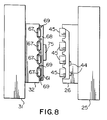
- the molding operation is performed using the conventional molding apparatus 17 partially illustrated in Fig. 4, and a mold generally indicated at 18 (Figs. 5 to 10) in accordance with the present invention.
- the molding apparatus 17 includes a heated extruder barrel 19 for receiving a plastic (in this case a glass reinforced nylon) from a hopper 20.
- the heated plastic is forced through an injection nozzle 1, at the outer end of the extruder 19.
- the extruder body 23 is slidably mounted on shafts 24 for movement towards and away from a fixed rectangular mandrel 25, which supports one mold half 26.
- Four shafts 28 (two shown) extend through the corners of the mandrel 25.
- each shaft 28 is fixedly mounted in a sleeve 29 on the outside of the mandrel 25, and the other end of each shaft is supported by the molding machine frame.
- a second mandrel 31, which supports a second mold half 32 is slidably mounted on the shafts 28 for movement towards and away from the mandrel 26.
- the extruder body 23 and the mandrel 31 are moved by hydraulic cylinders (not shown). Movement of the mold halves 26 and 32 to a closed position (Fig. 5) forms a mold with a cavity in the shape of the flange 10 for receiving plastic from the extruder barrel 19.
- the mold half 26 includes a rectangular body 34 with an injection orifice 35 extending therethrough for receiving fused or molten plastic from the head 21 of the extruder 17.
- the inner surface 37 of the body 34 is planar with top and bottom shoulders 38 and 39, respectively joined by a vertical projection 41.
- Concave troughs or grooves 42 separated by lands 43 are provided in the projection 41 for receiving the pipes 4 of the manifold 1.
- Elongated, generally U-shaped recesses 44 are provided in one side edge of the body 34 for receiving two of the pipes 4, i.e. for permitting full closing of the mold 18.
- Four posts 45 with one bevelled side 46 extend outwardly from the surface 47.
- Holes 48 are provided in the corners of the ends 38 and 29 for receiving aligning pins 49 near the corners of the other mold halve 32. The holes 48 and the pins 49 ensure that the mold halves 26 and 32 are precisely aligned in the closed position.
- the other mold half 32 includes a rectangular body 50 with raised top and bottom shoulders 52 and 53, respectively for abutting the shoulders 38 and 39 of the mold half 26.
- Four elongated concave recesses 54 extend inwardly from one side 56 of the body 50 for receiving the pipes 4 of the manifold 1.
- the inner ends 57 of the recesses 54 cooperate with flaring ends 59 of the recesses 44 (Fig. 6) to define the parts of a mold cavity in which the sleeves 12 are formed.
- the lands 60 between the recesses 54 abut the lands 43 between the recesses 44.
- the lugs 14 are formed by opposed small recesses 62 in the inner ends of the lands 60.
- a slide 61 is mounted on the inner surface of the body.
- the ends of the slide 6 extend into grooves 63 in the ends 52 and 53 of the body 50.
- the slide ends are slotted for sliding on pates 64.
- An arcuate groove 66 in the slide 61 receives plastic from the orifice 35 and feeds it to the mold cavity.
- Oval cross section projections 67 on one planar side 68 of the slide 61 receive the open ends 6 of the manifold pipes 4.
- Pins 69 on each side of the projections 67 enter recesses 70 and 72 in the inner ends of the lands 43 and 60, respectively for forming the holes through the tubular lugs 13, the holes 14, and the groove 16 in the lug 15 (only the outermost pins 69 are shown, the others being aligned therewith on the planar side 68 of the slide 61).
- the slide 61 is moved from an open position (to the right in Fig. 7) to a closed position (to the left in Fig. 7) in which the free ends of the pins 69 engage the inner ends of the recesses 70 and 72 by a hydraulic cylinder 74.
- the cylinder 74 is mounted on a plate 75 which is bolted to side 77 of the mold half 32. During closing of the mold, the plate 74 enters a shallow recess 78 in the side 80 of the mold half 26.
- a piston rod 89 extends through the plate 74 into an inclined or bevelled side 83 of the slide 61.
- a blow molded manifold is placed on the mold half 32 (Fig. 10).
- the closed ends 6 of the pipes 4 are open (i.e. the closed ends are removed following molding).
- the mold is closed (Fig. 5) by moving the mold half 32 against the mold half 26 to define a mold cavity around the ends 6 of the pipes 4.
- the plastic material glass filled nylon
- the ridges 7 help to anchor the flange 10 on the pipes.
- the mold is then opened and the completed part removed. For such purpose fingers (not shown) are provided in the mold half 32.
- the fingers are normally retracted. Referring to Fig. 9, the fingers are mounted in a plate 85 extending the length of the mold half 32.
- a piston rod 86 extending through the back of the mold half 32, is reciprocated by a hydraulic cylinder (not shown) to extend and retract the pins. Following opening of the mold, the piston rod 82 is retracted to move the slide 61 away from the molded flange, and the fingers are extended to eject the part.
- the outer free ends 6 of the pipes 4 produced by blow molding are closed. It will be appreciated that by making relatively minor variations to the mold halves, a flange 10 can be molded onto closed pipes 4, and the pipes can then be cut to open the outer ends thereof. It will also be appreciated that while (in the present case) the manifold pipes and the flange are formed of the same plastic, the material used in the two elements could be different, provided the materials are compatible, i.e. will stick together to form, in effect, a one-piece finished product.
Landscapes
- Engineering & Computer Science (AREA)
- Mechanical Engineering (AREA)
- Manufacturing & Machinery (AREA)
- Chemical & Material Sciences (AREA)
- Combustion & Propulsion (AREA)
- General Engineering & Computer Science (AREA)
- Moulds For Moulding Plastics Or The Like (AREA)
- Blow-Moulding Or Thermoforming Of Plastics Or The Like (AREA)
Claims (12)
- Methode zur Herstellung eines rohrförmigen Kunststoffartikels (1) mit einem Flansch (10), wobei der Artikel (1) aus einem Kunststoff-Vorformling geformt ist und der Flansch (10) dann auf den Artikel aufgebracht wird, wobei die Methode durch folgende Schritte gekennzeichnet wird:a) Blasformen des rohrförmigen Artikels (1) aus dem Kunststoff-Vorformling in einer ersten Form (18)b) gefolgt von Blasformen, Veränderung der ersten Form unter Bildung eines Formenhohlraums um den besagten Artikel (1), undc) Einspritzen eines mit dem Kunststoff des rohrförmigen Artikels (1) kompatiblen Kunststoffes in den besagten Hohlraum zur Bildung eines den Artikel (1) umgebenden und an ihm festhaftenden Flansches (10).
- Methode nach Anspruch 1 einschließlich folgender Schritte: Blasformen des rohrförmigen Artikels in einer ersten Form (18); Entnahme des rohrförmigen Artikels (1) aus der ersten Form ; Einsetzen des rohrförmigen Artikels in eine offene zweite Form; Schließen der zweiten Form zur Bestimmung des Formenhohlraums um den Artikel.
- Methode zum Formen eines Ansaugkrümmers (1) für einen Verbrennungsmotor, wobei der Krümmer (1) einen aus einem Kunststoff-Vorformling geformten länglichen Hohlkörper (2) sowie eine Mehrzahl an Rohren (4) enthält, die einerseits des Körpers (1) nach außen verlaufen, wobei die besagten Rohre (4) offene Außenenden (6) sowie einen auf die offenen Außenenden der Rohre (4) aufgebrachten Befestigungsflansch (10) aufweisen, wobei der Flansch (10) am Außenende jedes Rohrs eine Muffe (12) und einen länglichen flachen Körper (11) aufweist, der zwischen den Muffen (12) verläuft, mit denen er ein Stück bildet, wobei der flache Körper (11) die offenen Enden der Muffen (12) zur Befestigung des Krümmers (1) am Motor umgibt, wobei die Methode durch folgende Schritte gekennzeichnet ist:a) Blasformen des Hohlkörpers (11) und der Rohre (4) aus dem Kunststoff-Vorformling in einer ersten Form (18), wobei die Rohre (4) geschlossene freie Außenenden (6) aufweisen;b) gefolgt von dem Blasform-Schritt, wobei die geschlossenen Enden (6) der Rohre (4) geöffnet werden;c) Einsetzen der Rohre (4) in eine offene zweite Form einschließlich (i) erste und zweite Formhälften (26, 32), die Aussparungen (44, 54) zur Bestimmung eines Formenhohlraums um die freien Enden aller Rohre (14) im Bereich des freien Endes (6) jedes Rohrs (4) enthalten, (ii) einen Schieber (61) und (iii) Vorsprünge (67) am Schieber (61) zur Aufnahme der offenen Enden (6) der besagten Rohre (4);d) Bewegen des Schiebers (61) in eine geschlossene Stellung; Einfügen der Vorsprünge (67) in die offenen Enden (6) der Rohre (4) zur Zentrierung der Rohre (4) in der Form; Schließen der zweiten Form durch gleichzeitiges Bewegen der Formhälften (16, 27), wobei die Formhälften (26, 32) und der Schieber (61) den Formenhohlraum um die freien Enden (6) der Rohre (4) bestimmen;e) Einspritzen eines mit dem Kunststoff des Krümmers (1) kompatiblen Kunststoffs in den Formenhohlraum zur Bildung eines die Rohre (4) umgebenden und an ihnen festhaftenden Flansches (10);f) Öffnen der Form durch Auseinandenbewegen der besagten Formhälften (26, 32) und Gleiten des besagten Schiebers (61) in eine offene Stellung, wobei der damit fertiggestellte Krümmer (1) aus der zweiten Form entfernt wird.
- Methode nach Anspruch 3 einschließlich des folgenden Schrittes:g) Erhitzen der besagten Rohre (4) vor dem Einspritzen des Kunststoffs in den Formenhohlraum zur Förderung der Bindung zwischen den Rohren (4) und dem Flansch (10).
- Methode nach Anspruch 4, wobei die Rohre (4) erhitzt werden, bevor sie in die zweite Form gesetzt werden.
- Methode nach Anspruch 3, wobei der Krümmer und der Flansch (10) aus demselben glasgefüllten Nylon geformt werden.
- Methode nach Anspruch 6 einschließlich des Schrittes, in dem rohrförmige Nasen (13) in einem Stück mit dem besagten flachen Körper (11) geformt werden, um Motorbolzen mit einem Stift (69) auf dem besagten Schieber aufzunehmen, der sich in den besagten Formenhohlraum erstreckt, wenn die zweite Form geschlossen ist.
- Methode nach Anspruch 7, einschließlich des Schrittes, in dem ringförmige Ränder an den Außenenden der besagten Rohre (4) gebildet werden, um die Verankerung der Flanschmuffen (12) an den Rohren (4) zu ermöglichen.
- Form (18) zur Benutzung beim Spritzgießen eines Flansches (10) auf einem rohrförmigen Kunststoffartikel (1), die aus ersten und zweiten Formhälften (26) besteht; erste Aussparung (42) in der besagten ersten Formhälfte zur Aufnahme des Kunststoffartikels und zur Bestimmung eines Teils des Formenhohlraums; zweite Aussparung (54) in der besagten Formhälfte, ebenfalls zur Aufnahme des Kunststoffartikels und zur Bestimmung des Formenhohlraums; gekennzeichnet durch einen in der besagten zweiten Formhälfte (32) befestigten Schieber (61) zur Bewegung zwischen einer geschlossenen Stellung zur Bestimmung des Formenhohlraums und einer offenen Stellung zur Freigabe eines geformten Flansches (10); Vorsprung (67) an dem besagten Schieber zur Aufnahme eines offenen Endes (6) des besagten Kunststoffartikels (1) zur Zentrierung des Artikels im Formenhohlraum; Zylindervorrichtung (74) zur Bewegung des besagten Schiebers (61); Riegelvorrichtung (46, 83) für den lösbaren Verschluß des besagten Schiebers in geschlossener Stellung, wenn die Formhälften zusammengeschoben werden.
- Form nach Anspruch 9, einschließlich eines Stifts (69) an dem besagten Schieber (61), der sich bei geschlossener Stellung der Form in den Formenhohlraum erstreckt und an Formlöcher im Flansch angepaßt werden kann.
- Form nach Anspruch 9, wobei die besagte Riegelvorrichtung an der besagten ersten Formhälfte mit einem Pfosten (45) zum Eingreifen des besagten Schiebers (61) in geschlossener Stellung der Form versehen ist, um die Bewegung des besagten Schiebers vor der Öffnung der Form zu verhindern.
- Form nach Anspruch 11, wobei der besagte Schieber (61) und der besagte Pfosten (45) gegenüberliegende angeschrägte Oberflächen (46, 83) aufweisen, damit sie beim Schließen der Form bis zum gegenseitigen Eingreifen verschoben werden können.
Applications Claiming Priority (2)
| Application Number | Priority Date | Filing Date | Title |
|---|---|---|---|
| US87715092A | 1992-05-01 | 1992-05-01 | |
| US877150 | 1992-05-01 |
Publications (2)
| Publication Number | Publication Date |
|---|---|
| EP0567702A1 EP0567702A1 (de) | 1993-11-03 |
| EP0567702B1 true EP0567702B1 (de) | 1997-06-11 |
Family
ID=25369366
Family Applications (1)
| Application Number | Title | Priority Date | Filing Date |
|---|---|---|---|
| EP92309385A Expired - Lifetime EP0567702B1 (de) | 1992-05-01 | 1992-10-15 | Verfahren zum Formen eines Ansaugrohrs für Kraftfahrzeuge |
Country Status (5)
| Country | Link |
|---|---|
| US (1) | US5445782A (de) |
| EP (1) | EP0567702B1 (de) |
| CA (1) | CA2073935C (de) |
| DE (1) | DE69220357T2 (de) |
| ES (1) | ES2104846T3 (de) |
Cited By (2)
| Publication number | Priority date | Publication date | Assignee | Title |
|---|---|---|---|---|
| DE19909850A1 (de) * | 1999-03-08 | 2000-09-14 | Mahle Filtersysteme Gmbh | Sauganlage für eine Brennkraftmaschine |
| US6752113B2 (en) | 2001-07-20 | 2004-06-22 | Filterwerk Mann & Hummel Gmbh | Mounting arrangement for an intake manifold and a method of making same |
Families Citing this family (17)
| Publication number | Priority date | Publication date | Assignee | Title |
|---|---|---|---|---|
| JP3219407B2 (ja) * | 1990-11-26 | 2001-10-15 | エクセル株式会社 | 多層プラスチック管及びその製造方法 |
| WO1994000287A1 (fr) * | 1992-06-29 | 1994-01-06 | Tokai Rubber Industries, Ltd. | Procede de fabrication d'une conduite souple en resine |
| DE19757986A1 (de) * | 1997-12-24 | 1999-07-01 | Mann & Hummel Filter | Ansaugeinrichtung für einen Verbrennungsmotor |
| US6475424B1 (en) | 1998-05-14 | 2002-11-05 | Cambridge Industries, Inc. | Multi-process molding method and article produced by same |
| KR100331454B1 (ko) | 1998-09-01 | 2002-04-09 | 신구 이이치 | 다기통 내연기관에 있어서의 관성과급식 흡기매니폴드의 구조및 이 흡기매니폴드에 있어서의 브랜치파이프의 접합방법 |
| JP3394192B2 (ja) * | 1998-09-01 | 2003-04-07 | ジー・ピー・ダイキョー株式会社 | 合成樹脂製インテークマニホールド及びその製造方法 |
| DE19913501A1 (de) * | 1999-03-25 | 2000-11-16 | Mahle Filtersysteme Gmbh | Verfahren zum Verbinden von zwei Kunststoffbauteilen |
| DE19913500A1 (de) * | 1999-03-25 | 2000-09-28 | Mahle Filtersysteme Gmbh | Verfahren zum Verbinden von zwei Kunststoffbauteilen |
| JP3705225B2 (ja) * | 2002-02-22 | 2005-10-12 | トヨタ紡織株式会社 | 合成樹脂製中空成形体の製造装置及び製造方法 |
| US7291302B2 (en) * | 2003-07-28 | 2007-11-06 | Toyoda Boshoku Corporation | Manufacturing method for synthetic resin hollow molded body |
| WO2005033499A1 (es) * | 2003-10-08 | 2005-04-14 | Nagares, S.A. | Modulo calentador de los gases de admision de un motor de automoción con control electronico de la temperatura incorporado |
| DE102006060144A1 (de) * | 2006-12-18 | 2008-06-19 | Mahle International Gmbh | Verfahren und Vorrichtung zum Herstellen eines Rohrs |
| ES2401617B1 (es) | 2011-08-05 | 2014-04-01 | Fundació Privada Ascamm | Procedimiento para la fabricación de conductos de aire de material plástico y molde utilizado |
| US9227353B2 (en) * | 2012-11-08 | 2016-01-05 | Solar Hydronics Corporation | Molding apparatus and method for operating same |
| US10208721B2 (en) * | 2017-03-15 | 2019-02-19 | Brp-Rotax Gmbh & Co. Kg | Method and system for manufacturing a family of intake manifolds for a family of internal combustion engines |
| CN112223689A (zh) * | 2020-08-13 | 2021-01-15 | 安徽科正模具有限公司 | 一种汽车发动机进气歧管注塑模具 |
| CN117921936B (zh) * | 2024-03-25 | 2024-05-28 | 江苏达威新材料科技有限公司 | 一种发动机进气歧管注塑装置 |
Family Cites Families (20)
| Publication number | Priority date | Publication date | Assignee | Title |
|---|---|---|---|---|
| US2991500A (en) * | 1954-06-14 | 1961-07-11 | Hagen Norbert | Method and apparatus for making plastic containers |
| DE1479381A1 (de) * | 1965-05-22 | 1969-05-08 | Kautex Werke Gmbh | Verfahren und Vorrichtung zum Herstellen von Hohlkoerpern aus thermoplastischem Material |
| US3291670A (en) * | 1965-12-02 | 1966-12-13 | Atlantic Res Corp | Method of making plastic pipe fittings |
| US3496600A (en) * | 1967-04-03 | 1970-02-24 | Nrm Corp | Blow molding machine |
| JPS5128742B2 (de) * | 1972-08-22 | 1976-08-20 | ||
| US3917789A (en) * | 1973-02-20 | 1975-11-04 | Raymond A Heisler | Method for molding a plastic container having a molded handle pivotally retained by an integrally formed attachment |
| JPS5832013B2 (ja) * | 1977-07-25 | 1983-07-09 | 大同特殊鋼株式会社 | スライド式異形鉄筋接合機 |
| US4197071A (en) * | 1978-09-29 | 1980-04-08 | Mueller Engineering & Manufacturing Company Incorporated | Safety device for continuous rotary molding machines |
| IL57898A (en) | 1979-07-26 | 1983-05-15 | Helioset Advanced Tech | Method for injection-molding of elements onto extruded units |
| FR2526364B1 (fr) * | 1982-05-10 | 1987-01-23 | Katashi Aoki | Machine de moulage par etirage et soufflage, apres injection |
| CA1172813A (en) * | 1982-06-16 | 1984-08-21 | Lupke, Manfred A. A. | Apparatus for producing multi-walled thermoplastic tubing |
| JPS6018307A (ja) | 1983-07-11 | 1985-01-30 | 旭化成株式会社 | 成形用母型 |
| JPS61293821A (ja) * | 1985-06-21 | 1986-12-24 | Takiron Co Ltd | コルゲ−ト管のスリ−ブの成形方法 |
| JPS6251426A (ja) * | 1985-08-30 | 1987-03-06 | Yoshida Kogyo Kk <Ykk> | 二重壁多口ブロ−成形品の製造方法及びその成形品 |
| JPS62116119A (ja) * | 1985-11-16 | 1987-05-27 | Takiron Co Ltd | 波形管のスリ−ブの成形方法 |
| JPS62181130A (ja) * | 1986-02-06 | 1987-08-08 | Nissei Ee S B Kikai Kk | 把手付き中空容器の成形方法 |
| JPH0739147B2 (ja) * | 1986-12-19 | 1995-05-01 | 日産自動車株式会社 | 樹脂製インテ−クマニホ−ルド |
| JPS63290715A (ja) | 1987-05-22 | 1988-11-28 | Mitsutoyo Jushi Kk | 合成樹脂製ブロー成形管の製造方法 |
| US5057266A (en) * | 1988-07-21 | 1991-10-15 | Sabel Plastechs, Inc. | Method of making a hollow polyethylene terephthalate blow molded article with an integral external projection such as a handle |
| EP0550776B1 (de) * | 1992-01-10 | 1997-04-09 | Excell Corporation | Verfahren zur Herstellung eines Hohlgegenstandes aus Kunststoff mit einem radialen Vorsprung |
-
1992
- 1992-07-15 CA CA002073935A patent/CA2073935C/en not_active Expired - Fee Related
- 1992-10-15 EP EP92309385A patent/EP0567702B1/de not_active Expired - Lifetime
- 1992-10-15 ES ES92309385T patent/ES2104846T3/es not_active Expired - Lifetime
- 1992-10-15 DE DE69220357T patent/DE69220357T2/de not_active Expired - Fee Related
-
1994
- 1994-03-21 US US08/216,242 patent/US5445782A/en not_active Expired - Lifetime
Cited By (4)
| Publication number | Priority date | Publication date | Assignee | Title |
|---|---|---|---|---|
| DE19909850A1 (de) * | 1999-03-08 | 2000-09-14 | Mahle Filtersysteme Gmbh | Sauganlage für eine Brennkraftmaschine |
| WO2000053919A1 (de) | 1999-03-08 | 2000-09-14 | Mahle Filtersysteme Gmbh | Sauganlage für eine brennkraftmaschine |
| US6581561B1 (en) | 1999-03-08 | 2003-06-24 | Mahle Filtersysteme Gmbh | Suction system for an internal combustion engine |
| US6752113B2 (en) | 2001-07-20 | 2004-06-22 | Filterwerk Mann & Hummel Gmbh | Mounting arrangement for an intake manifold and a method of making same |
Also Published As
| Publication number | Publication date |
|---|---|
| US5445782A (en) | 1995-08-29 |
| DE69220357T2 (de) | 1997-12-11 |
| DE69220357D1 (de) | 1997-07-17 |
| CA2073935C (en) | 2000-10-17 |
| EP0567702A1 (de) | 1993-11-03 |
| ES2104846T3 (es) | 1997-10-16 |
| CA2073935A1 (en) | 1993-11-02 |
Similar Documents
| Publication | Publication Date | Title |
|---|---|---|
| EP0567702B1 (de) | Verfahren zum Formen eines Ansaugrohrs für Kraftfahrzeuge | |
| CA1043067A (en) | Method and apparatus for making oriented hollow plastic articles | |
| EP0269217B1 (de) | Verfahren zum Spritzgiessen und dabei hergestelltes Kunststoffteil | |
| US6042364A (en) | Mold assembly for manufacturing hollow parts | |
| EP0709173B1 (de) | Giessverfahren und Vorrichtung | |
| EP0913241B1 (de) | Ansaugkrümmer aus kunststoff und verfahren und vorrichtung zu seiner herstellung | |
| SK90995A3 (en) | Method and apparatus for manufacturing hollow objects, in particular plastic preforms | |
| CN208558210U (zh) | 塑壳模具 | |
| CA1152275A (en) | Injection moulding process and apparatus | |
| CN206510359U (zh) | 一种假肢注塑件以及注塑模具 | |
| CA2283722A1 (en) | Process for manufacturing hollow plastic objects | |
| JPH0576901B2 (de) | ||
| CN212288412U (zh) | 用于制造高韧高强聚丙烯塑料保鲜盒的注塑模具 | |
| EP3663070B1 (de) | Verfahren zum blasformen | |
| CN208359345U (zh) | 一种汽车前灯罩成型模中的斜顶机构 | |
| CN209504764U (zh) | 一种新型模仁结构及具有该结构的汽车配件成型模具 | |
| JP2976264B2 (ja) | 三層構造成形品の射出成形方法およびその金型 | |
| CN223058304U (zh) | 一种盖勺一体注塑模具 | |
| CN114286742A (zh) | 用于形成热塑性制品的模制方法 | |
| CN218615262U (zh) | 具有滑块进胶机构的汽车后保险杠电镀装饰条模具 | |
| JP3643820B2 (ja) | 異種/異色材一体形の射出成形方法およびその装置 | |
| JPH0811155A (ja) | 中空成形品の成形方法 | |
| CN216032223U (zh) | 具有气封式免剪浇口机构的筒状塑件注塑模具 | |
| CN215242505U (zh) | 多镶块高精度注塑模具 | |
| CN222094686U (zh) | 一种具有涂料增补喷涂结构的压缩机壳体压铸模具 |
Legal Events
| Date | Code | Title | Description |
|---|---|---|---|
| PUAI | Public reference made under article 153(3) epc to a published international application that has entered the european phase |
Free format text: ORIGINAL CODE: 0009012 |
|
| AK | Designated contracting states |
Kind code of ref document: A1 Designated state(s): DE ES FR GB IT |
|
| 17P | Request for examination filed |
Effective date: 19940323 |
|
| 17Q | First examination report despatched |
Effective date: 19950728 |
|
| GRAG | Despatch of communication of intention to grant |
Free format text: ORIGINAL CODE: EPIDOS AGRA |
|
| GRAH | Despatch of communication of intention to grant a patent |
Free format text: ORIGINAL CODE: EPIDOS IGRA |
|
| GRAH | Despatch of communication of intention to grant a patent |
Free format text: ORIGINAL CODE: EPIDOS IGRA |
|
| GRAA | (expected) grant |
Free format text: ORIGINAL CODE: 0009210 |
|
| AK | Designated contracting states |
Kind code of ref document: B1 Designated state(s): DE ES FR GB IT |
|
| REF | Corresponds to: |
Ref document number: 69220357 Country of ref document: DE Date of ref document: 19970717 |
|
| ITF | It: translation for a ep patent filed | ||
| ET | Fr: translation filed | ||
| REG | Reference to a national code |
Ref country code: ES Ref legal event code: FG2A Ref document number: 2104846 Country of ref document: ES Kind code of ref document: T3 |
|
| PLBE | No opposition filed within time limit |
Free format text: ORIGINAL CODE: 0009261 |
|
| 26N | No opposition filed | ||
| REG | Reference to a national code |
Ref country code: GB Ref legal event code: IF02 |
|
| PGFP | Annual fee paid to national office [announced via postgrant information from national office to epo] |
Ref country code: FR Payment date: 20031003 Year of fee payment: 12 |
|
| PGFP | Annual fee paid to national office [announced via postgrant information from national office to epo] |
Ref country code: GB Payment date: 20031016 Year of fee payment: 12 |
|
| PGFP | Annual fee paid to national office [announced via postgrant information from national office to epo] |
Ref country code: DE Payment date: 20031023 Year of fee payment: 12 |
|
| PGFP | Annual fee paid to national office [announced via postgrant information from national office to epo] |
Ref country code: ES Payment date: 20031126 Year of fee payment: 12 |
|
| PG25 | Lapsed in a contracting state [announced via postgrant information from national office to epo] |
Ref country code: GB Free format text: LAPSE BECAUSE OF NON-PAYMENT OF DUE FEES Effective date: 20041015 |
|
| PG25 | Lapsed in a contracting state [announced via postgrant information from national office to epo] |
Ref country code: ES Free format text: LAPSE BECAUSE OF NON-PAYMENT OF DUE FEES Effective date: 20041016 |
|
| PG25 | Lapsed in a contracting state [announced via postgrant information from national office to epo] |
Ref country code: DE Free format text: LAPSE BECAUSE OF NON-PAYMENT OF DUE FEES Effective date: 20050503 |
|
| GBPC | Gb: european patent ceased through non-payment of renewal fee |
Effective date: 20041015 |
|
| PG25 | Lapsed in a contracting state [announced via postgrant information from national office to epo] |
Ref country code: FR Free format text: LAPSE BECAUSE OF NON-PAYMENT OF DUE FEES Effective date: 20050630 |
|
| REG | Reference to a national code |
Ref country code: FR Ref legal event code: ST |
|
| PG25 | Lapsed in a contracting state [announced via postgrant information from national office to epo] |
Ref country code: IT Free format text: LAPSE BECAUSE OF NON-PAYMENT OF DUE FEES;WARNING: LAPSES OF ITALIAN PATENTS WITH EFFECTIVE DATE BEFORE 2007 MAY HAVE OCCURRED AT ANY TIME BEFORE 2007. THE CORRECT EFFECTIVE DATE MAY BE DIFFERENT FROM THE ONE RECORDED. Effective date: 20051015 |
|
| REG | Reference to a national code |
Ref country code: ES Ref legal event code: FD2A Effective date: 20041016 |