EP0569936A1 - Verpackungsmaschine mit einer Schneideinrichtung - Google Patents
Verpackungsmaschine mit einer Schneideinrichtung Download PDFInfo
- Publication number
- EP0569936A1 EP0569936A1 EP93107649A EP93107649A EP0569936A1 EP 0569936 A1 EP0569936 A1 EP 0569936A1 EP 93107649 A EP93107649 A EP 93107649A EP 93107649 A EP93107649 A EP 93107649A EP 0569936 A1 EP0569936 A1 EP 0569936A1
- Authority
- EP
- European Patent Office
- Prior art keywords
- piston
- knife
- abutment
- cutting
- moved
- Prior art date
- Legal status (The legal status is an assumption and is not a legal conclusion. Google has not performed a legal analysis and makes no representation as to the accuracy of the status listed.)
- Granted
Links
Images

Classifications
-
- B—PERFORMING OPERATIONS; TRANSPORTING
- B65—CONVEYING; PACKING; STORING; HANDLING THIN OR FILAMENTARY MATERIAL
- B65B—MACHINES, APPARATUS OR DEVICES FOR, OR METHODS OF, PACKAGING ARTICLES OR MATERIALS; UNPACKING
- B65B61/00—Auxiliary devices, not otherwise provided for, for operating on sheets, blanks, webs, binding material, containers or packages
- B65B61/04—Auxiliary devices, not otherwise provided for, for operating on sheets, blanks, webs, binding material, containers or packages for severing webs, or for separating joined packages
- B65B61/06—Auxiliary devices, not otherwise provided for, for operating on sheets, blanks, webs, binding material, containers or packages for severing webs, or for separating joined packages by cutting
-
- B—PERFORMING OPERATIONS; TRANSPORTING
- B26—HAND CUTTING TOOLS; CUTTING; SEVERING
- B26D—CUTTING; DETAILS COMMON TO MACHINES FOR PERFORATING, PUNCHING, CUTTING-OUT, STAMPING-OUT OR SEVERING
- B26D5/00—Arrangements for operating and controlling machines or devices for cutting, cutting-out, stamping-out, punching, perforating, or severing by means other than cutting
- B26D5/02—Means for moving the cutting member into its operative position for cutting
Definitions
- the invention relates to a packaging machine with a cutting device according to the preamble of claim 1.
- the abutment of the film to the level of the film to be separated is moved in a known manner and then locked.
- the knife lying on the opposite side of the film web engages and cuts the film web in cooperation with the abutment.
- Undesirable bending forces occur which adversely affect the cutting result.
- the object of the invention is to modify the packaging machine of the type described in the introduction in such a way that the cutting device is improved in such a way that the disadvantage described is avoided becomes. This object is achieved by a packaging machine characterized in claim 1.
- the packaging machine has a machine frame 1 and, arranged one after the other, a molding station 2, an evacuation and sealing station 3 and a cutting device 4.
- a film web 5 is introduced into the machine from the input side in the packaging machine.
- containers are formed from the film web. After filling, these are sealed in the evacuation and sealing station and finally separated from one another by means of the cutting device 4.
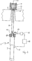
- the cutting device comprises a piston-cylinder device 6 arranged below the film web 5, which extends essentially in the vertical direction and which has a cylinder 7 and a piston 8 which extends upwards.
- the upper free end of the piston is designed as the actual abutment 9 for the knife 12 and has a bearing surface for the film web 5 with an immersion slot 10 for the knife 12.
- the piston-cylinder device 6 is connected to a compressed air source, not shown.
- the piston-cylinder device is designed such that the abutment, when the compressed air supplied to the cylinder is in contact, just reaches the underside of the film web.
- the knife device 11 comprises a cutting knife 12 which lies directly above the film web 5 and on the point opposite the abutment.
- the actual knife 12 is connected to a pneumatically operated drive, with the aid of which the knife can be moved through the film web 5 into the immersion slot 10 and can be returned to the retracted position.
- the piston rod 8 has a slot 13 extending perpendicular to its axis.
- a wedge 14 is provided which is mounted so as to be displaceable in the direction perpendicular to the axis of the piston, that is to say in the horizontal direction, and which is connected on one side to a drive device 15 which moves the wedge in its guide in such a way that the wedge between the shaft shown in FIG 2 shown retracted position and a position in which the wedge is moved into the slot 13, is reciprocable.
- the piston device has a marking.
- a sensor 17 is arranged so that it detects the marking when the abutment is just in the extended position described above.
- the output of the sensor is connected to an input of a controller 18.
- An output of the control is connected to the control input of the drive device 15.
- the inclined plane of the wedge 13 is chosen so that the thicker end of the wedge lies on the side connected to the drive.
- the wedge 14 is initially in the retracted position in such a way that the piston rod can be moved directly on the film web from the lowered position into the position described above and shown in FIG. 2 without hindrance.
- the drive device 15 is switched on via the control 18, as a result of which the wedge moves into the slot and thus an additional mechanical force is exerted in the direction of the film web, so that the latter around a little bit is biased upwards.
- the wedge then remains locked until the actual cutting process has taken place by immersing the knife 12. The force thereby generated is not transmitted to the piston-cylinder device but to the wedge or the abutment 19 carrying it.
Landscapes
- Engineering & Computer Science (AREA)
- Mechanical Engineering (AREA)
- Life Sciences & Earth Sciences (AREA)
- Forests & Forestry (AREA)
- Auxiliary Devices For And Details Of Packaging Control (AREA)
- Containers And Plastic Fillers For Packaging (AREA)
- Nonmetal Cutting Devices (AREA)
Abstract
Description
- Die Erfindung betrifft eine Verpackungsmaschine mit einer Schneideinrichtung nach dem Oberbegriff des Patentanspruches 1.
- Bei einer Verpackungsmaschine mit einer Schneideinrichtung wird in bekannter Weise das Widerlager des zur Ebene der zu trennenden Folie bewegt und dann arretiert. In dieser arretierten Stellung greift das auf der gegenüberliegenden Seite der Folienbahn liegende Messer ein und trennt die Folienbahn in Zusammenwirken mit dem Widerlager durch. Dabei treten unerwünschte Biegekräfte auf, die das Schneideergebnis nachteilig beeinflussen.
- Aufgabe der Erfindung ist es, die Verpackungsmaschine der eingangs beschriebenen Art so abzuwandeln, daß die Schneideinrichtung derart verbessert wird, daß der beschriebene Nachteil vermieden wird. Diese Aufgabe wird durch eine im Patentanspruch 1 gekennzeichnete Verpackungsmaschine gelöst.
- Weitere Merkmale und Zweckmäßigkeiten der Erfindung ergeben sich aus der Beschreibung eines Ausführungsbeispieles anhand der Figuren. Von den Figuren zeigen:
- Fig. 1
- Eine Seitenansicht einer Verpackungsmaschine mit weggelassener Seitenabdeckung und
- Fig. 2
- eine Seitenansicht, einer Schneideinrichtung für eine solche Verpackungsmaschine, teilweise in geschnittener Darstellung.
- Die Verpackungsmaschine weist einen Maschinenrahmen 1 und nacheinander angeordnet eine Formstation 2, eine Evakuier- und Versiegelungsstation 3 und eine Schneideinrichtung 4 auf. In der Verpackungsmaschine wird eine Folienbahn 5 von der Eingangsseite in die Maschine eingeführt. In der Formstation werden aus der Folienbahn Behälter geformt. Diese werden nach dem Befüllen in der Evakuier- und Versiegelungsstation versiegelt und schließlich mittels der Schneideinrichtung 4 voneinander getrennt.
- Die Schneideinrichtung umfaßt eine unterhalb der Folienbahn 5 angeordnete Kolben-Zylindereinrichtung 6, die sich im wesentlichen in vertikaler Richtung erstreckt und die einen Zylinder 7 und einen nach oben sich erstreckenden Kolben 8 aufweist. Das obere freie Ende des Kolbens ist als das eigentliche Widerlager 9 für das Messer 12 ausgebildet und besitzt eine Auflagefläche für die Folienbahn 5 mit einem Eintauchschlitz 10 für das Messer 12. Die Kolben-Zylindereinrichtung 6 ist mit einer nicht gezeigten Druckluftquelle verbunden. Die Kolben-Zylindereinrichtung ist so ausgebildet, daß das Widerlager bei Anliegen der dem Zylinder zugeführten Druckluft gerade bis auf die Unterseite der Folienbahn gelangt.
- Die Messereinrichtung 11 umfaßt ein Schneidmesser 12, welches unmittelbar oberhalb der Folienbahn 5 und auf der dem Widerlager gegenüberliegenden Stelle liegt. Das eigentliche Messer 12 ist mit einem pneumatik betriebenen Antrieb verbunden, mit Hilfe dessen das Messer zum Schneiden durch die Folienbahn 5 hindurch in den Eintauchschlitz 10 bewegbar und in die zurückgezogene Stelle zurückführbar ist.
- Die Kolbenstange 8 weist einen sich senkrecht zu ihrer Achse erstreckenden Schlitz 13 auf. Es ist ein Keil 14 vorgesehen, der in der Richtung senkrecht zur Achse des Kolbens, also in waagerechter Richtung verschiebbar gelagert ist und der auf einer Seite mit einer den Keil in seiner Führung bewegenden Antriebseinrichtung 15 derart verbunden ist, daß der Keil zwischen der in Fig. 2 gezeigten zurückgezogenen Stellung und einer Stellung, bei der der Keil in den Schlitz 13 hinein bewegt ist, hin- und herbewegbar ist. Die Kolbeneinrichtung weist eine Markierung auf. Es ist ein Sensor 17 so angeordnet, daß er die Markierung erfaßt, wenn das Widerlager gerade in der oben beschriebenen ausgefahrenen Stellung ist. Der Ausgang des Sensors ist mit einem Eingang einer Steuerung 18 verbunden. Ein Ausgang der Steuerung ist mit dem Steuereingang der Antriebseinrichtung 15 verbunden. Die schiefe Ebene des Keiles 13 ist so gewählt, daß das dickere Ende des Keiles auf der mit dem Antrieb verbundenen Seite liegt.
- Im Betrieb befindet sich der Keil 14 zunächst in der zurückgezogenen Stellung derart, daß die Kolbenstange unbehindert von dem Keil aus ihrer abgesenkten Stellung in die oben beschriebene und in Fig. 2 gezeigte Stellung unmittelbar an der Folienbahn bewegbar ist. Sobald der Sensor 17 durch Erfassen der Markierung feststellt, daß diese Stellung erreicht ist, wird über die Steuerung 18 die Antriebseinrichtung 15 eingeschaltet, wodurch der Keil in den Schlitz bewegt und damit eine zusätzliche mechanische Kraft in Richtung auf die Folienbahn ausgeübt wird, so daß diese um ein kleines Stück nach oben vorgespannt wird. Der Keil bleibt dann arretiert, bis der eigentliche Schneidvorgang durch Eintauchen des Messers 12 erfolgt ist. Dabei wird die dabei entstehende Kraft nicht auf die Kolben-Zylindereinrichtung sondern auf den Keil beziehungsweise das diesen tragene Widerlager 19 übertragen.
Claims (3)
- Verpackungsmaschine mit einer Schneideinrichtung, bei der ein Widerlager und ein Messer auf gegenüberliegenden Seiten einer zu trennenden Packungsmaterialbahn angeordnet sind, wobei das Widerlager zum Bewegen bis zur Folienbahn mit einer pneumatisch betriebenen Kolben-Zylinder-Einrichtung verbunden ist,
dadurch gekennzeichnet, daß die Kolben-Zylinder-Einrichtung mit einem an dem Kolben angreifenden Element verbunden ist, welches über einen von einer Steuerung angesteuerten Antrieb so bewegbar ist, daß der Kolben bei Erreichen einer durch das Beaufschlagen des Zylinders mit Druckluft erreichten Endstellung um ein weiteres Stück gegen das Messer bewegt und die Kolbenstange dann zum Schneiden in ihrer Stellung verriegelt wird. - Verpackungsmaschine mit einer Schneideinrichtung nach Anspruch 1,
dadurch gekennzeichnet, daß die bei der mittels des Elementes erreichten Endstellung eine Kraft ausgeübt wird, die höher ist als die von der Kolben-Zylindereinrichtung aufbringbare Kraft. - Verpackungsmaschine mit einer Schneideinrichtung, welche zunächst eine Bahn von zusammenhängenden Packungen herstellt, wobei ein Widerlager und ein Messer auf gegenüberliegenden Seiten der dann zu durchtrennenden Bahn angeordnet sind, wobei das Widerlager zum periodischen Bewegen aus einer zurückgezogenen Stellung in eine erste Stellung bis zur Folienbahn mit einer pneumatisch betriebenen Kolben-Zylinder-Einrichtung (6) verbunden ist, und wobei eine Verriegelungseinrichtung zum Verriegeln der Kolbenstange (8), in der Schneidstellung mittels eines durch einen gesteuerten Antrieb bewegten, an ihr angreifenden Elementes vorgesehen ist,
dadurch gekennzeichnet, daß die Kolbenstange (8) das Widerlager trägt und daß das an ihr angreifende Element (14) so ausgebildet und über den von der Steuerung (14) angesteuerten Antrieb so bewegbar ist, daß die Kolbenstange (8) beim Erreichen der durch das Beaufschlagen des Zylinders (7) mit Druckluft erreichten ersten Stellung durch das Element (14) um ein weiteres Stück gegen das Messer in eine zweite Stellung bewegt und die Kolbenstange (8) dann durch das Element (14) zum Schneiden in dieser zweiten Stellung verriegelt wird, worauf das Messer zum Schneiden betätigt wird.
Applications Claiming Priority (2)
| Application Number | Priority Date | Filing Date | Title |
|---|---|---|---|
| DE4216207 | 1992-05-15 | ||
| DE4216207A DE4216207C1 (de) | 1992-05-15 | 1992-05-15 |
Publications (2)
| Publication Number | Publication Date |
|---|---|
| EP0569936A1 true EP0569936A1 (de) | 1993-11-18 |
| EP0569936B1 EP0569936B1 (de) | 1996-09-11 |
Family
ID=6459037
Family Applications (1)
| Application Number | Title | Priority Date | Filing Date |
|---|---|---|---|
| EP93107649A Expired - Lifetime EP0569936B1 (de) | 1992-05-15 | 1993-05-11 | Verpackungsmaschine mit einer Schneideinrichtung |
Country Status (3)
| Country | Link |
|---|---|
| EP (1) | EP0569936B1 (de) |
| DE (2) | DE4216207C1 (de) |
| ES (1) | ES2094411T3 (de) |
Families Citing this family (5)
| Publication number | Priority date | Publication date | Assignee | Title |
|---|---|---|---|---|
| EP0895933B2 (de) * | 1997-08-08 | 2007-03-07 | Multivac Sepp Haggenmüller Kg | Hubeinrichtung für eine Arbeitsstation einer Verpackungsmaschine |
| DE20313228U1 (de) * | 2003-08-27 | 2005-01-05 | Nicepac Gmbh | Vorrichtung zum Schneiden von Folien |
| DE102008035223A1 (de) | 2008-07-29 | 2010-02-04 | Multivac Sepp Haggenmüller Gmbh & Co. Kg | Verpackungsmaschine mit Einpunkt-Werkzeugverriegelung |
| DE102010026409A1 (de) * | 2010-07-07 | 2012-01-12 | Wemhöner Systems Technologies AG | Verfahren und Vorrichtung zum Durchtrennen einer laufenden Materialbahn |
| DE102022107346A1 (de) | 2022-03-29 | 2023-10-05 | Multivac Sepp Haggenmüller Se & Co. Kg | Hubwerk mit Verriegelung sowie Verfahren |
Citations (2)
| Publication number | Priority date | Publication date | Assignee | Title |
|---|---|---|---|---|
| US2130618A (en) * | 1936-09-03 | 1938-09-20 | Westinghouse Air Brake Co | Fluid pressure motor and locking means therefor |
| US3574291A (en) * | 1968-09-26 | 1971-04-13 | Illinois Tool Works | Packaging apparatus |
Family Cites Families (3)
| Publication number | Priority date | Publication date | Assignee | Title |
|---|---|---|---|---|
| US3805486A (en) * | 1972-05-31 | 1974-04-23 | Mahaffy & Harder Eng Co | Packaging apparatus and techniques |
| DE3118946A1 (de) * | 1981-05-13 | 1982-12-16 | Krämer + Grebe GmbH & Co KG Maschinenfabrik, 3560 Biedenkopf | Vorrichtung zum austrennen von muldenfoermig tiefgezogenen, befuellten kunststoff-packungen aus den folienbahnen |
| DE3619811A1 (de) * | 1986-06-12 | 1987-12-17 | Kraemer & Grebe Kg | Druckluftantrieb fuer stanz-, schneid- und praegeeinrichtungen |
-
1992
- 1992-05-15 DE DE4216207A patent/DE4216207C1/de not_active Expired - Fee Related
-
1993
- 1993-05-11 DE DE59303714T patent/DE59303714D1/de not_active Expired - Fee Related
- 1993-05-11 EP EP93107649A patent/EP0569936B1/de not_active Expired - Lifetime
- 1993-05-11 ES ES93107649T patent/ES2094411T3/es not_active Expired - Lifetime
Patent Citations (2)
| Publication number | Priority date | Publication date | Assignee | Title |
|---|---|---|---|---|
| US2130618A (en) * | 1936-09-03 | 1938-09-20 | Westinghouse Air Brake Co | Fluid pressure motor and locking means therefor |
| US3574291A (en) * | 1968-09-26 | 1971-04-13 | Illinois Tool Works | Packaging apparatus |
Also Published As
| Publication number | Publication date |
|---|---|
| ES2094411T3 (es) | 1997-01-16 |
| DE4216207C1 (de) | 1993-08-19 |
| EP0569936B1 (de) | 1996-09-11 |
| DE59303714D1 (de) | 1996-10-17 |
Similar Documents
| Publication | Publication Date | Title |
|---|---|---|
| EP0321590B1 (de) | Verfahren und Vorrichtung zum Herstellen eines eine scharfe Schneidkante aufweisenden Stanzwerkzeugs | |
| EP1554109B1 (de) | Vorrichtung zum stanzen, prägen und/oder verformen flacher elemente | |
| EP0529272A1 (de) | Einrichtung zur Aufnahme von biegeschlaffen flächigen Teilen | |
| EP0194353A1 (de) | Vorrichtung zur Sicherung von Ausfallstücken an einer Elektroerosionsmaschine | |
| EP0895934A1 (de) | Hubeinrichtung für eine Arbeitsstation einer Verpackungsmaschine | |
| DE1596464C3 (de) | Vorrichtung zum fernsteuerbaren Einstellen von werkzeugtragenden Schlitten | |
| CH664732A5 (de) | Geraet zum verbinden der enden eines thermoplastischen kunststoffbandes. | |
| DE2158907B2 (de) | Verfahren und Vorrichtung zum Ausbrechen vorgestanzter Materialstücke aus bogenförmigen Materialbahnen | |
| DE2524487B2 (de) | Vorrichtung zum Herstellen und Bündeln von Etiketten | |
| EP0569936B1 (de) | Verpackungsmaschine mit einer Schneideinrichtung | |
| EP0792814A1 (de) | Auspackmaschine für Rollen, insbesondere Druckpapierrollen | |
| DE2643507A1 (de) | Vorrichtung zum schrittweisen vorschub von platten | |
| EP0265589B1 (de) | Schneidpresse | |
| DE2719957B2 (de) | Etikettiervorrichtung | |
| AT404810B (de) | Unterflursägemaschine | |
| DE19823400B4 (de) | Umreifungsmaschine | |
| DE3108337A1 (de) | Strangpressmaschine und verfahren zum betrieb einer strangpressmaschine | |
| DE102005023720A1 (de) | Längsschneidvorrichtung für kontinuierlich geförderte Materialbahnen und Verfahren hierfür | |
| DD274188A1 (de) | Vorrichtung zum ablaengen von bandfoermigen material | |
| DE102019219058A1 (de) | Verpackungsmaschine sowie Verfahren mit Umfaltfunktion | |
| DE69101563T2 (de) | Klebebandmaschine für Behälter. | |
| DE3511685C2 (de) | ||
| DE19621205A1 (de) | Abtrennvorrichtung | |
| DE19647012B4 (de) | Sägekopf zum Schneiden linear bewegten Materials in Querrichtung | |
| DE2502268B2 (de) | Vorrichtung zum anschweissen von draht an ein traegermaterial |
Legal Events
| Date | Code | Title | Description |
|---|---|---|---|
| PUAI | Public reference made under article 153(3) epc to a published international application that has entered the european phase |
Free format text: ORIGINAL CODE: 0009012 |
|
| AK | Designated contracting states |
Kind code of ref document: A1 Designated state(s): DE ES FR IT |
|
| 17P | Request for examination filed |
Effective date: 19931109 |
|
| 17Q | First examination report despatched |
Effective date: 19950203 |
|
| GRAH | Despatch of communication of intention to grant a patent |
Free format text: ORIGINAL CODE: EPIDOS IGRA |
|
| GRAA | (expected) grant |
Free format text: ORIGINAL CODE: 0009210 |
|
| GRAH | Despatch of communication of intention to grant a patent |
Free format text: ORIGINAL CODE: EPIDOS IGRA |
|
| AK | Designated contracting states |
Kind code of ref document: B1 Designated state(s): DE ES FR IT |
|
| ET | Fr: translation filed | ||
| REF | Corresponds to: |
Ref document number: 59303714 Country of ref document: DE Date of ref document: 19961017 |
|
| ITF | It: translation for a ep patent filed | ||
| REG | Reference to a national code |
Ref country code: ES Ref legal event code: FG2A Ref document number: 2094411 Country of ref document: ES Kind code of ref document: T3 |
|
| PLBI | Opposition filed |
Free format text: ORIGINAL CODE: 0009260 |
|
| PLBQ | Unpublished change to opponent data |
Free format text: ORIGINAL CODE: EPIDOS OPPO |
|
| PLBF | Reply of patent proprietor to notice(s) of opposition |
Free format text: ORIGINAL CODE: EPIDOS OBSO |
|
| 26 | Opposition filed |
Opponent name: TIROMAT KRAEMER + GREBE GMBH & CO. KG Effective date: 19970528 |
|
| PLBF | Reply of patent proprietor to notice(s) of opposition |
Free format text: ORIGINAL CODE: EPIDOS OBSO |
|
| PLBO | Opposition rejected |
Free format text: ORIGINAL CODE: EPIDOS REJO |
|
| PLBN | Opposition rejected |
Free format text: ORIGINAL CODE: 0009273 |
|
| 27O | Opposition rejected |
Effective date: 19990304 |
|
| PGFP | Annual fee paid to national office [announced via postgrant information from national office to epo] |
Ref country code: ES Payment date: 20090522 Year of fee payment: 17 |
|
| PGFP | Annual fee paid to national office [announced via postgrant information from national office to epo] |
Ref country code: IT Payment date: 20090527 Year of fee payment: 17 Ref country code: FR Payment date: 20090519 Year of fee payment: 17 Ref country code: DE Payment date: 20090529 Year of fee payment: 17 |
|
| REG | Reference to a national code |
Ref country code: FR Ref legal event code: ST Effective date: 20110131 |
|
| PG25 | Lapsed in a contracting state [announced via postgrant information from national office to epo] |
Ref country code: IT Free format text: LAPSE BECAUSE OF NON-PAYMENT OF DUE FEES Effective date: 20100511 |
|
| PG25 | Lapsed in a contracting state [announced via postgrant information from national office to epo] |
Ref country code: DE Free format text: LAPSE BECAUSE OF NON-PAYMENT OF DUE FEES Effective date: 20101201 |
|
| PG25 | Lapsed in a contracting state [announced via postgrant information from national office to epo] |
Ref country code: FR Free format text: LAPSE BECAUSE OF NON-PAYMENT OF DUE FEES Effective date: 20100531 |
|
| REG | Reference to a national code |
Ref country code: ES Ref legal event code: FD2A Effective date: 20111118 |
|
| PG25 | Lapsed in a contracting state [announced via postgrant information from national office to epo] |
Ref country code: ES Free format text: LAPSE BECAUSE OF NON-PAYMENT OF DUE FEES Effective date: 20100512 |