EP0570984B1 - Unterdrücken von Rauschen und Verzerrungen in einem Lichtwellenleitersystem - Google Patents
Unterdrücken von Rauschen und Verzerrungen in einem Lichtwellenleitersystem Download PDFInfo
- Publication number
- EP0570984B1 EP0570984B1 EP93108297A EP93108297A EP0570984B1 EP 0570984 B1 EP0570984 B1 EP 0570984B1 EP 93108297 A EP93108297 A EP 93108297A EP 93108297 A EP93108297 A EP 93108297A EP 0570984 B1 EP0570984 B1 EP 0570984B1
- Authority
- EP
- European Patent Office
- Prior art keywords
- signal
- frequency
- laser
- chirp
- chirp generating
- Prior art date
- Legal status (The legal status is an assumption and is not a legal conclusion. Google has not performed a legal analysis and makes no representation as to the accuracy of the status listed.)
- Expired - Lifetime
Links
Images


Classifications
-
- H—ELECTRICITY
- H04—ELECTRIC COMMUNICATION TECHNIQUE
- H04B—TRANSMISSION
- H04B15/00—Suppression or limitation of noise or interference
-
- H—ELECTRICITY
- H04—ELECTRIC COMMUNICATION TECHNIQUE
- H04B—TRANSMISSION
- H04B10/00—Transmission systems employing electromagnetic waves other than radio-waves, e.g. infrared, visible or ultraviolet light, or employing corpuscular radiation, e.g. quantum communication
- H04B10/25—Arrangements specific to fibre transmission
- H04B10/2507—Arrangements specific to fibre transmission for the reduction or elimination of distortion or dispersion
Definitions
- the invention relates to a fiber-optic communications system according to the preamble part of claim 1 and to a method according to the preamble part of claim 12.
- Directly modulating the analog intensity of a semiconductor laser with an electrical signal is considered among the simplest methods known in the art for transmitting optical signals carrying information, such as sound and video signals, through optical fibers.
- optical signals are susceptible to noise and distortion.
- Much of the noise which degrades signal quality is produced by light scattering and reflection effects within the optical fiber.
- Rayleigh scattering occurs due to localized variations in density within optical fibers, which are inherent to glass.
- Reflection occurs due to discrete components, such as, for example, connectors, splices, and detectors.
- Both scattering and reflection contribute to noise generated at the source and noise received at the end of the system.
- Optical feedback due to discrete reflectors or distributed reflection from Rayleigh backscattering in the glass fiber can cause instabilities in the light source, including optical power fluctuations and distortion instabilities. Such instabilities degrade the quality of the transmitted analog signal.
- interferometric noise and distortion will be produced at the receiving end of the link from the mixing in the photodetector of directly transmitted light with light that has been twice reflected.
- a prechirp technique which is applied to an optical transmitter which uses an external intensity modulator.
- the prechirp technique achieves to double the allowable transmission fiber dispersion and is applicable for long-span transoceanic transmission systems.
- the laser diode injection current is first modulated with a sinusoidal waveform. Then the laser diode output is intensity modulated by an external modulator with RZ format.
- the object of the present invention is to provide a low-cost fiber-optic communication system and a method for such a system which is able to suppress noise and distortion due to scattering and reflections.
- the chirp generating signal is combined with the RF input signal of a laser.
- the chirp generating signal modulates the optical frequency of (chirps) the laser output, thereby broadening the laser optical spectrum. This broadened spectrum spreads interferometric noise and distortion in the RF output signal over a wide interval and pushes much of the noise and distortion outside the system bandwidth where it will not affect signal quality.
- an alternate embodiment of the present invention includes a predistorter which is tuned to apply a predistortion signal to the system which offsets the expected second-order intermodulation products.
- the present invention is used in a conventional fiber-optic system, as shown in FIG. 1.
- the system includes a laser 2 and a receiver 4 coupled by an optical fiber link 6 with optical connectors 8.
- an RF input signal is used to intensity modulate the output of the laser.
- all lasers exhibit optical frequency modulation to some extent caused by the RF input signal.
- the optical signal is transmitted by the laser through the link.
- the receiver detects the optical signal and accordingly generates an RF output signal substantially similar to the RF input signal.
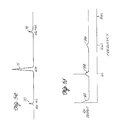
- the laser will generate an optical spectrum, as shown in FIG. 5a.
- sidebands 52, 54, 56, 58 appear offset from the main optical carrier 50. The number of sidebands and the amplitude of each sideband depends on the amount of amplitude modulation and frequency modulation of the laser.
- Noise and distortion in conventional fiber-optic systems degrade the overall performance of the system.
- Optical mixing of directly transmitted light from the laser with doubly-reflected light produces noise bands 62, 64, 66 in the RF output near DC and near harmonics of the modulation frequency ⁇ m , as shown in FIG. 5b.
- These noise bands also known as interferometric noise, degrade signal quality.
- interferometric noise caused by double-backscattering refer to an article by S. Wu, A. Yariv, H. Blauvelt, and N. Kwong, entitled "Theoretical and Experimental Investigation of Conversion of Phase Noise to Intensity Noise by Rayleigh Scattering in Optical Fibers" appearing in the Applied Physics Letters, Vol.
- a system for suppressing noise and distortion includes a chirp signal generator 5 coupled to an RF input path to the laser 2.
- the laser is coupled to the receiver 4 by the optical fiber link 6 having connectors 8.
- the chirp signal generator produces a chirp generating signal which is used to modulate the optical frequency of the laser output.
- the chirp generating signal may be a simple sine wave having a characteristic frequency, or it may be a more complex signal having a frequency spectrum, for example, a frequency modulated sine wave.
- the combined input to the laser will be I m cos ⁇ m t + I c cos ⁇ c t.
- the combined input broadens the spectrum of the optical carrier 50' and sidebands 52', 54', 56', 58', as shown in FIG. 5c.
- the broadened spectrum effectively spreads noise 62', 64', 66' in the RF output signal from the receiver over wider frequency ranges, as shown in FIG. 5d.
- the spreading of noise over a wider frequency interval makes the system more desirable. In many systems, much of the noise can be pushed outside the system bandwidth.
- distortion in fiber-optic systems can also be caused by closely-spaced optical connectors 8 which cause discrete reflections.
- the resulting optical spectrum will have sidebands 70, 72, as shown in FIG. 5e.
- the number of sidebands and the amplitude of each sideband depends on the amount of amplitude modulation and frequency modulation of the laser.
- the corresponding undesirable noise and distortion products 82, 84, 86 in the RF output are shown in FIG. 5f.
- FIG. 5f shows an intermediate case with both discrete distortion products and noise bands.
- the optical carrier 71' and sidebands 70', 72' are split into relatively low amplitude subbands 90, 92 separated by the chirp generating signal frequency ⁇ c , as shown in FIG. 5g.
- ⁇ c is small compared to the laser linewidth, the subbands will overlap, as shown in FIG. 5c.
- the total noise and distortion of the system is not changed, but the noise and distortion products 82', 84', 86' in the RF output are spread out over a wider frequency interval, as shown in FIG. 5h, making it less objectionable for most applications.
- some lasers exhibit second-order distortion due to the combination of the chirp generating signal and the RF input. To distinguish this from distortion due to optical mixing, this will be referred to as laser distortion. Intermodulation products due to laser distortion can have a detrimental effect on signal quality if they fall within the information band of the RF signal. The effect of these second-order laser intermodulation products can be minimized by two techniques. First, the RF signal can be predistorted to offset the laser distortion products. Second, a spread-spectrum chirp generating signal may be used, such as a frequency-modulated carrier, filtered noise, or a pseudo-random digital signal. This does not reduce overall laser distortion power, but spreads the laser distortion over a wider interval.
- FIG. 3 An alternate embodiment of a noise and distortion suppression system having a predistorter for canceling second-order laser intermodulation products is shown in FIG. 3.
- the system includes a predistorter 13 connected in series with a diplex filter 17 and a source laser 2 which generates optical signals for transmission through an optical fiber link 6 having connectors 8 to a remote receiver 4.
- the chirp generating signal from the generator 5 is separately applied to both the predistorter and the diplex filter through first and second attenuators, 19, 21.
- Undesirable laser distortion due to the combination of the chirp generating signal and the RF input signal can be corrected by predistorting the RF signal at the predistorter such that the distortion generated by the laser is canceled.
- the predistorter 13 has an RF input 12 to which the RF signal is applied and a laser chirp generating signal input 14 to which a portion of chirp generating signal is applied.
- the amount of predistortion is controlled through, for example, the first variable attenuator 19.
- the output of the first attenuator is coupled to the predistorter input 14.
- the RF signal has an information component containing the information, such as cellular telephone or video signals, for example, to be transmitted optically by laser.
- the information component has an informational bandwidth.
- the predistorter produces an intermodulation distortion signal which is added to the RF signal at output 16.
- the signal from the output of the predistorter feeds into a high pass filter capacitor 36 within a diplex filter 17.
- the chirp generating signal from the second attenuator 21 is applied across the low pass filter inductor 38.
- the signal is attenuated by an appropriately valued resistor, for example, within the second attenuator to ensure that the laser is not driven out of its linear region.
- the chirp generating signal combines with the output of the predistorter at network node 40.
- the resulting signal from the diplex filter is applied as drive current to the laser.
- the intermodulation distortion generated in the laser by the combination of the chirp generating signal and RF input signal is equal in amplitude and opposite in sign to that generated by the intermodulation distortion signal from the predistorter. The net effect is to cancel the intermodulation distortion present in the RF output from the receiver.
- the system is initiated with the predistorter set to generate negligible distortion, i.e., the first attenuator is set at maximum attenuation.
- a chirp generating signal level is selected by using the second attenuator to minimize noise and distortion in the RF output signal. If this choice of signal causes in-band laser distortion due to the chirp generating signal, the predistorter level is adjusted until the in-band laser distortion is effective canceled. To achieve distortion cancellation, it is sometimes required to invert the chirp generating signal that is applied to the predistorter relative to the signal applied to the diplex filter.
- an exemplary predistorter suitable for use with the system of FIG. 3 comprises an amplitude modulator 13 which creates intermodulation products which are equal in amplitude, but opposite in sign, to the intermodulation products produced by laser distortion.
- the level of the intermodulation products produced by the predistorter is proportional to the level of chirp generating signal input to the predistorter.
- the amplitude modulator has its RF input 12 and output 16 capacitively coupled by an input capacitor 18 and an output capacitor 20.
- the capacitors block low-frequency signals, but allow RF signals to pass.
- a first terminal 22 of a resistor 24 is connected between the two capacitors.
- the second terminal 26 of the resistor is connected to one terminal 28 of a PIN diode 30.
- the other terminal 32 of the PIN diode is connected to ground.
- the PIN diode 30 and resistor 24 together act as a current controlled variable resistor which draws power from the RF signal dependent on the current across the PIN diode.
- the chirp generating signal applied to a second modulator input 14 across an inductor 34 which has one terminal connected between the resistor 24 and the PIN diode, controls the current across the PIN diode.
- the amount of predistortion can also be controlled by adjusting the bias current through the PIN diode.
- the system of FIG. 3 having a predistorter as shown in FIG. 3a is suitable for systems which use a relatively low-frequency chirp generating signal in the range from approximately 1KHz to 200 KHz.
- laser distortion due to the chirp generating signal and the RF signal can generally be characterized as amplitude modulation.
- higher frequency chirp generating signals in the megahertz range may cause laser distortion that can be characterized as phase modulation of the RF output in addition to amplitude modulation.
- the predistorter shown in FIG. 3a may not be suitable, and a more elaborate predistorter may be required.
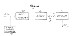
- FIG. 4 A further embodiment of a noise and distortion suppression system with a predistorter suitable for use with relatively high-frequency chirp generating signals is shown in FIG. 4.
- the circuit includes a chirp signal generator 5 coupled to the input path for an RF input signal to a predistorter 35.
- the chirp signal generator produces a chirp generating signal which combines with the RF input signal to the predistorter.
- the predistorter generates intermodulation distortion to cancel any in-band distortion generated by the laser.
- a suitable predistorter for the system of FIG. 4 is disclosed in US-A-4,992,754.
- predistortion is not always necessary to preserve the information carried on the RF signal. Predistortion is only required when the combination of the chirp generating signal and the RF input signal causes in-band laser distortion which is unacceptable for a particular system. In-band laser distortion of the information component of the RF signal depends on the frequency of the chirp generating signal compared to the informational bandwidth of the information component of the RF signal.
- the band of the signal is from 500 to 550 MHz.
- the chirp generating signal may have a frequency of 100 MHz. This modulating frequency does not interfere directly with any in-band frequency.
- the second-order intermodulation products with the information component of the signal are less than 450 MHz and higher than 600 MHz, which are also outside the band of the signal.
- a chirp generating signal which does not distort the information on the RF signal. If the frequency of the chirp generating signal is less than the informational bandwidth, distortion may occur due to intermodulation products within the information band, and it may be necessary to predistort the RF signal to preserve the accuracy of the information.
- the band of the signal is from 50 to 550 MHz (characteristic of many CATV networks).
- a 100 MHz chirp generating signal would be within the signal band and, therefore, unsuitable. Instead, one may modulate with a chirp generating signal having a frequency of 100 KHz, for example. This is clearly outside the band, so does not interfere directly. It has, however, intermodulation products which are in-band. Therefore, the RF signal should be predistorted to preserve the information on the signal.
- the chirp generating signal must not be of too low a frequency.
- noise and distortion is caused by the mixing of doubly transmitted light with directly transmitted light. If the chirp generating signal induces no significant change in the instantaneous optical frequency during the delay for the doubly reflected light to mix with directly transmitted light, the chirp will not be effective.
- the maximum time delay that can be expected from optical fiber links is of the order of a few hundred microseconds. As a practical lower limit, a chirp generating signal of 1 KHz, for example, would be sufficient to suppress the noise and distortion for this time delay. Other systems might have time delays which are significantly shorter, resulting in a higher minimum frequency for the chirp generating signal.
- a frequency of up to 200 KHz is presently preferred. That is about the maximum rate that effective thermal chirping occurs. Below 200 KHz, the laser chirp is primarily due to thermal effects, and the chirp parameter (having units of MHz/mA) is about ten times larger than for higher chirp generating frequencies. It is particularly preferred that the chirp generating signal frequency is in the range of from 10 to 200 KHz. With low frequency chirping signals, a smaller amplitude is required to produce the desired noise and distortion suppression.
- the frequency of the chirp generating signal is greater than the bandwidth of the information signal and less than the lowest frequency of the band.
- the circuits required to modulate and predistort the RF signal before it reaches the source laser become more complicated and costly.
- the effectiveness of the chirping technique depends on the FM modulation index. This index is the ratio of the optical frequency deviation to the chirp generating frequency.
- the frequency of the chirp generating signal preferably should not exceed 300 MHz.
- the laser may be necessary to chirp the laser with a chirp generating signal frequency greater than the highest frequency of the information band. This would be necessary, for example, when a discrete reflector is close to the source laser, requiring a high-frequency signal to chirp the laser optical frequency before the reflected light returns to the laser.
- the chirp generating signal amplitude remain constant for reducing the complexity of the system. If the chirp generating signal amplitude varies, the effectiveness of the avoidance of noise problems would be reduced, since the lower amplitude portions of the chirp generating signal would cause less change in the frequency of the light and result in less suppression of noise and distortion due to optical mixing of doubly reflected light and directly transmitted light.
- the chirp generating signal generators may include apparatus to produce spread-spectrum chirp generating signals.
- Spread-spectrum chirp generating signals are complex signals with frequency spectra containing a range of frequencies as opposed to a single characteristic frequency. Such signals are used to optical frequency modulate the laser, producing second-order intermodulation products which are spread across the band.
- One suitable spread-spectrum generator is a frequency modulated tone, for example, with a frequency spectrum extending from 10 KHz to 100 KHz. Such a signal may be used to transfer information while also causing optical frequency modulation. With this generator, the laser distortion power is distributed over the frequency interval of 10 to 100 KHz from the carrier and the distortion is more tolerable in most systems.
- a filtered noise generator is a filtered noise generator.
- a generator for example, may include a noise diode which generates white noise which is amplified and suitably filtered. In effect, one introduces out-of-band noise to modulate the laser output for the purpose of reducing in-band noise and distortion of the RF output signal from the receiver.
- Still another suitable spread-spectrum generator is a pseudo-random digital pattern noise generator.
Landscapes
- Engineering & Computer Science (AREA)
- Computer Networks & Wireless Communication (AREA)
- Signal Processing (AREA)
- Physics & Mathematics (AREA)
- Electromagnetism (AREA)
- Optical Communication System (AREA)
Claims (13)
- Lichtwellenleiterkommunikationssystem mit einem Laser (2), der mit einem Lichtwellenleiter (6) verbunden ist, und mit einem HF Eingangssignal mit einem Informationsfrequenzband zur Modulation des Lasers,einer Einrichtung (5) zur Erzeugung eines Chirp-Erzeugungssignals, das wenigstens eine Frequenz aufweist, gekennzeichnet durcheine Einrichtung zum Kombinieren des Chirp-Erzeugungssignals mit dem HF Eingangssignal, undeine Einrichtung, um das kombinierte HF Eingangssignal und Chirp-Erzeugungssignal an den Laser anzulegen, um den Laser zu modulieren und zu chirpen.
- Das System nach Anspruch 1, wobei die Chirp-Erzeugungssignalfrequenz kleiner als die niedrigste Frequenz in dem Informationsband oder größer als die höchste Frequenz in dem Informationsband ist.
- Das System nach einem der Ansprüche 1 oder 2, wobei das Chirp-Erzeugungssignal eine Mehrzahl von Frequenzen umfaßt.
- Das System nach irgendeinem der vorhergehenden Ansprüche, wobei das Chirp-Erzeugungssignal eine Frequenz aufweist, die, wenn sie mit irgendeiner Frequenz in dem Informationsband kombiniert wird, keine Intermodulationsprodukte zweiter Ordnung mit irgendeiner Frequenz in dem Informationsband erzeugt, die in die Bandbreite des Informationsbandes fallen.
- Das System nach irgendeinem der vorhergehenden Ansprüche, wobei die Einrichtung (5) zur Erzeugung eines Chirp-Erzeugungssignals eine Einrichtung zur Erzeugung von gefiltertem Rauschen umfaßt.
- Das System nach irgendeinem der Ansprüche 1 bis 4, wobei die Einrichtung zur Erzeugung eines Chirp-Erzeugungssignals eine Einrichtung zur Erzeugung von pseudozufälligen, digitalen Signalen umfaßt.
- Das System nach irgendeinem der vorhergehenden Ansprüche, wobei Chirp-Erzeugungssignals eine Frequenz in dem Bereich von 1 KHz bis 300 MHz und vorzugsweise von weniger als 200 KHz aufweist.
- Das System nach irgendeinem der vorhergehenden Ansprüche, das des weiteren eine Einrichtung (13) zur Vorverzerrung des HF Eingangssignals als eine Funktion des Chirp-Erzeugungssignals umfaßt, so daß die Laserverzerrung der Informationskomponente des HF Ausgangssignals aufgehoben wird, die durch das Chirp-Erzeugungssignal erzeugt wird.
- Das System nach irgendeinem der vorhergehenden Ansprüche, wobei die Einrichtung zum Anlegen eines Chirp-Erzeugungssignals einen Oszillator mit konstanter Amplitude umfaßt.
- Das System nach irgendeinem der Ansprüche 1 bis 8, wobei die Einrichtung zum Anlegen eines Chirp-Erzeugungssignals eine Einrichtung zur Erzeugung eines frequenzmodulierten Signals umfaßt.
- Das System nach irgendeinem der vorhergehenden Ansprüche, wobei die Einrichtung zum Anlegen eines Chirp-Erzeugungssignals einen Oszillator umfaßt, der eine Modulationsfrequenz aufweist, die keine Intermodulationsprodukte mit irgendeiner Frequenz in der Informationskomponente bewirkt, die in das Informationsband fallen.
- Ein Verfahren zur Unterdrückung von Rauschen und Verzerrung in einem Lichtwellenleiterkommunikationssystem, das einen Laser aufweist, dessen optischer Ausgang mit einem fernliegenden Empfänger gekoppelt ist, wobei das Verfahren die Schritte umfaßt, ein HF Signal, das eine Informationsbandbreite hat, an den Laser anzulegen, um den optischen Laserausgang zu modulieren, und ein Chirp-Erzeugungssignal zu erzeugen, das wenigstens eine Frequenz aufweist, gekennzeichnet durchKombinieren des Chirp-Erzeugungssignals mit dem HF Eingangssignal;Anlegen des kombinierten Signals an den Laser zur Frequenzmodulation des optischen Laserausgangs, undDemodulieren des optischen Laserausgangs bei dem Empfänger zur Erzeugung eines HF Ausgangssignal mit geringem Rauschen, das im wesentlichen gleich dem HF Eingangssignal ist.
- Das Verfahren des Anspruchs 12, wobei der Schritt, ein Chirp-Erzeugungssignal an den Laser anzulegen, umfaßt, das HF Eingangssignal zur Aufhebung irgendeiner Laserverzerrung vorzuverzerren, die durch Modulation des optischen Laserausgangs mit dem Chirp-Erzeugungssignal bewirkt worden ist.
Applications Claiming Priority (2)
| Application Number | Priority Date | Filing Date | Title |
|---|---|---|---|
| US07/887,533 US5430569A (en) | 1992-05-22 | 1992-05-22 | Suppression of noise and distortion in fiber-optic systems |
| US887533 | 1997-07-03 |
Publications (2)
| Publication Number | Publication Date |
|---|---|
| EP0570984A1 EP0570984A1 (de) | 1993-11-24 |
| EP0570984B1 true EP0570984B1 (de) | 1998-08-05 |
Family
ID=25391355
Family Applications (1)
| Application Number | Title | Priority Date | Filing Date |
|---|---|---|---|
| EP93108297A Expired - Lifetime EP0570984B1 (de) | 1992-05-22 | 1993-05-21 | Unterdrücken von Rauschen und Verzerrungen in einem Lichtwellenleitersystem |
Country Status (7)
| Country | Link |
|---|---|
| US (2) | US5430569A (de) |
| EP (1) | EP0570984B1 (de) |
| JP (1) | JP2937691B2 (de) |
| KR (1) | KR930024335A (de) |
| CN (1) | CN1054440C (de) |
| CA (1) | CA2096795A1 (de) |
| DE (1) | DE69320101T2 (de) |
Families Citing this family (70)
| Publication number | Priority date | Publication date | Assignee | Title |
|---|---|---|---|---|
| US6011506A (en) * | 1993-02-17 | 2000-01-04 | Li; Ming-Chiang | Different models for RF signal train generators and interferoceivers |
| US6107954A (en) * | 1991-11-04 | 2000-08-22 | Li; Ming-Chiang | Optical RF support network |
| GB9508901D0 (en) * | 1995-05-02 | 1995-06-21 | Northern Telecom Ltd | Communications system |
| IT1276024B1 (it) * | 1995-10-12 | 1997-10-24 | Pirelli Cavi S P A Ora Pirelli | Sistema di polarizzazione di un modulatore ottico per cavi |
| US5812294A (en) * | 1996-06-03 | 1998-09-22 | Lucent Technologies Inc. | Linearized optical transmitter |
| US6122043A (en) * | 1996-06-06 | 2000-09-19 | Gn Nettest (New York) Inc. | Method and apparatus for electrically reducing coherence/polarization noise in reflectometers |
| US5872624A (en) * | 1997-06-05 | 1999-02-16 | Gn Nettest (New York) | Method and apparatus for retroreflectively reducing coherence/polarization noise in reflectometers |
| US5923414A (en) * | 1996-06-06 | 1999-07-13 | Gn Nettest New York, Inc. | Method and apparatus for thermally reducing coherence/polarization noise in reflectometers |
| US5781327A (en) * | 1996-08-19 | 1998-07-14 | Trw Inc. | Optically efficient high dynamic range electro-optic modulator |
| US5892607A (en) * | 1996-10-23 | 1999-04-06 | Scientific-Atlanta, Inc. | Suppression of stimulated brillouin scattering in optical transmission system |
| US6271942B1 (en) | 1996-11-26 | 2001-08-07 | Matsushita Electric Industrial Co., Ltd. | Optical transmission device and system |
| JPH10164024A (ja) * | 1996-12-05 | 1998-06-19 | Nec Corp | 波長多重伝送用光送信器 |
| US5850305A (en) * | 1996-12-18 | 1998-12-15 | Scientific-Atlanta, Inc. | Adaptive predistortion control for optical external modulation |
| JP3748652B2 (ja) | 1997-02-27 | 2006-02-22 | 富士通株式会社 | インラインアンプを用いた光伝送システム |
| JPH10242909A (ja) | 1997-02-27 | 1998-09-11 | Fujitsu Ltd | 光伝送システム |
| US6055043A (en) * | 1997-06-05 | 2000-04-25 | Gn Nettest New York, Inc. | Method and apparatus for using phase modulation to reduce coherence/polarization noise in reflectometers |
| US6587257B1 (en) * | 1997-06-12 | 2003-07-01 | Telecommunications Research Laboratories | Non-linear subcarrier predistortion and upconversion system |
| US5870513A (en) * | 1997-06-17 | 1999-02-09 | Cable Television Laboratories, Inc. | Bidirectional cable network with a mixing tap for suppressing undesirable noise in signals from a remote end of the network |
| US5892865A (en) * | 1997-06-17 | 1999-04-06 | Cable Television Laboratories, Inc. | Peak limiter for suppressing undesirable energy in a return path of a bidirectional cable network |
| US6654958B1 (en) * | 1997-12-16 | 2003-11-25 | Koninklijke Philips Electronics N.V. | Reference signal generator for return path aligning |
| US6026105A (en) * | 1998-02-23 | 2000-02-15 | Lucent Technologies, Inc. | Technique for measuring semiconductor laser chirp |
| US6320191B1 (en) | 1998-03-27 | 2001-11-20 | Picometrix, Inc. | Dispersive precompensator for use in an electromagnetic radiation generation and detection system |
| US6529305B1 (en) * | 1998-11-04 | 2003-03-04 | Corvis Corporation | Optical transmission apparatuses, methods, and systems |
| US6118566A (en) | 1998-11-04 | 2000-09-12 | Corvis Corporation | Optical upconverter apparatuses, methods, and systems |
| US6292598B1 (en) * | 1998-11-04 | 2001-09-18 | Corvis Corporation | Optical transmission apparatuses, methods, and systems |
| EP1142179A1 (de) * | 1998-12-15 | 2001-10-10 | Ortel Corporation | Schaltung zur unterdrückung von rauschen und verzerrung in lineare faseroptischen verbindungen |
| US6590683B1 (en) * | 1999-02-04 | 2003-07-08 | Lockheed Martin Corporation | Bandwidth efficient phase shift keyed modulation over nonlinear distortion limited optical fiber links |
| US6204718B1 (en) * | 1999-06-25 | 2001-03-20 | Scientific-Atlanta, Inc. | Method and apparatus for generating second-order predistortion without third-order distortion |
| US6687466B1 (en) * | 2000-01-06 | 2004-02-03 | Adc Telecommunications, Inc. | Dynamic distortion control |
| US6917764B1 (en) * | 2000-09-29 | 2005-07-12 | Emcore Corporation | Predistortion circuit with combined odd-order and even-order correction |
| DE60106860T2 (de) * | 2001-02-14 | 2005-03-10 | Alcatel | Modulierungsschema und Übertragungssystem für NRZ-Signale mit links- und rechtsseitiger Filterung |
| KR20020096079A (ko) * | 2001-06-15 | 2002-12-31 | 주식회사 에치에프알 | 반송파 신호를 이용하여 임펄스 노이즈를 개선한 광 전송장치 및 방법 |
| KR100590521B1 (ko) * | 2001-06-20 | 2006-06-15 | 삼성전자주식회사 | 무선통신시스템에서 비선형성 왜곡을 감소시킨 광중계기 |
| US20030002115A1 (en) * | 2001-07-02 | 2003-01-02 | Koninklijke Philips Electronics N.V. | Dynamic NPR boost |
| SE523873C2 (sv) * | 2002-03-19 | 2004-05-25 | Ericsson Telefon Ab L M | Metod för predistortion av icke-linjära anordningar |
| US7142788B2 (en) * | 2002-04-16 | 2006-11-28 | Corvis Corporation | Optical communications systems, devices, and methods |
| KR20030083355A (ko) * | 2002-04-22 | 2003-10-30 | (주)애니람다 | 광전송시 어커스토-옵틱 효과를 적용하여 노이즈 플로어증가를 억제하는 방법 |
| US6661815B1 (en) * | 2002-12-31 | 2003-12-09 | Intel Corporation | Servo technique for concurrent wavelength locking and stimulated brillouin scattering suppression |
| US7199446B1 (en) | 2003-02-18 | 2007-04-03 | K2 Optronics, Inc. | Stacked electrical resistor pad for optical fiber attachment |
| US7340184B2 (en) * | 2003-05-01 | 2008-03-04 | Optium Corporation | Linearized Optical Transmitter Using Feedback Control |
| US7466925B2 (en) * | 2004-03-19 | 2008-12-16 | Emcore Corporation | Directly modulated laser optical transmission system |
| JP2005277713A (ja) * | 2004-03-24 | 2005-10-06 | Toshiba Corp | 光伝送システムとその光送信装置 |
| US7548567B2 (en) * | 2004-04-02 | 2009-06-16 | Vladimir Kupershmidt | Analog transmitter using an external cavity laser (ECL) |
| US7412174B2 (en) * | 2004-05-05 | 2008-08-12 | Emcore Corporation | Method and apparatus for distortion control for optical transmitters |
| US20060017607A1 (en) * | 2004-07-26 | 2006-01-26 | Kyocera Corporation | Amplitude modulator, selector switch, high frequency transmitting/receiving apparatus including the same, and radar apparatus, and radar apparatus-mounting vehicle and radar apparatus-mounting small ship |
| TWI330474B (en) * | 2004-09-21 | 2010-09-11 | Emcore Corp | Method and apparatus for distortion control for optical transmitters |
| US7575380B2 (en) * | 2004-10-15 | 2009-08-18 | Emcore Corporation | Integrated optical fiber and electro-optical converter |
| US20060251425A1 (en) * | 2004-12-23 | 2006-11-09 | K2 Optronics | Suppression of fiber-induced noise caused by narrow linewidth lasers |
| US7761011B2 (en) * | 2005-02-23 | 2010-07-20 | Kg Technology Associates, Inc. | Optical fiber communication link |
| USRE44647E1 (en) | 2005-03-15 | 2013-12-17 | Emcore Corporation | Directly modulated laser optical transmission system with phase modulation |
| US7848661B2 (en) * | 2005-03-15 | 2010-12-07 | Emcore Corporation | Directly modulated laser optical transmission system with phase modulation |
| US20060222004A1 (en) * | 2005-04-01 | 2006-10-05 | International Business Machines Corporation | Methods and apparatus for transferring data |
| KR100827278B1 (ko) * | 2005-05-17 | 2008-05-07 | 가부시끼가이샤 도시바 | 광 신호 전송 장치 및 신호 처리 방법 |
| US8064777B2 (en) * | 2005-06-13 | 2011-11-22 | Arris Group, Inc. | Four quadrant linearizer |
| US7596326B2 (en) * | 2005-10-27 | 2009-09-29 | Emcore Corporation | Distortion cancellation circuitry for optical receivers |
| JP4872319B2 (ja) * | 2005-11-18 | 2012-02-08 | 日本電気株式会社 | 光信号送受信システム、光波長多重伝送システム、光送受信装置、および光波長多重伝送方法 |
| US7881621B2 (en) * | 2006-03-02 | 2011-02-01 | Emcore Corporation | Optical transmission system with directly modulated laser and feed forward noise cancellation |
| US7792432B2 (en) * | 2006-03-02 | 2010-09-07 | Emcore Corporation | Externally modulated laser optical transmission system with feed forward noise cancellation |
| US7634198B2 (en) * | 2006-06-21 | 2009-12-15 | Emcore Corporation | In-line distortion cancellation circuits for linearization of electronic and optical signals with phase and frequency adjustment |
| US9231705B1 (en) | 2007-10-31 | 2016-01-05 | Emcore Coporation | Communication system with QAM modulation |
| US8718484B2 (en) * | 2007-10-31 | 2014-05-06 | Emcore Corporation | Laser optical transmission system with dual modulation |
| US7945172B2 (en) * | 2008-05-20 | 2011-05-17 | Harmonic, Inc. | Dispersion compensation circuitry and system for analog video transmission with direct modulated laser |
| US20100150560A1 (en) * | 2008-12-12 | 2010-06-17 | Electronics And Communications Research Institute | Apparatus and method for transmitting optical signals with enhanced reflection sensitivity in wavelength division multiplexing passive optical network (wdm-pon) |
| CA2855345A1 (en) * | 2011-11-09 | 2014-05-16 | Aurora Networks, Inc. | Catv transmission system using analog small form factor pluggable modules |
| US20140230536A1 (en) * | 2013-02-15 | 2014-08-21 | Baker Hughes Incorporated | Distributed acoustic monitoring via time-sheared incoherent frequency domain reflectometry |
| US9602218B2 (en) * | 2014-07-25 | 2017-03-21 | Arris Enterprises, Inc. | Directly modulated laser with dispersion compensation |
| US10256934B2 (en) * | 2016-10-11 | 2019-04-09 | Zte Corporation | Chirp managed laser generation for next generation passive optical networks |
| JP6900784B2 (ja) * | 2017-05-24 | 2021-07-07 | 富士通株式会社 | 発光素子駆動回路、光モジュールおよびアクティブオプティカルケーブル |
| CN113504167B (zh) * | 2021-08-06 | 2022-03-18 | 深圳市量宇科技有限公司 | 一种超低浓度颗粒物检测方法及其检测系统 |
| US20230256258A1 (en) * | 2022-02-15 | 2023-08-17 | Biothread Llc | Footwear and insert having therapeutic light source |
Family Cites Families (21)
| Publication number | Priority date | Publication date | Assignee | Title |
|---|---|---|---|---|
| US3820037A (en) * | 1972-09-25 | 1974-06-25 | Martin Marietta Corp | Laser control system |
| US4011403A (en) * | 1976-03-30 | 1977-03-08 | Northwestern University | Fiber optic laser illuminators |
| US4357713A (en) * | 1979-09-12 | 1982-11-02 | The United States Of America As Represented By The Secretary Of The Army | Method and apparatus for reduction of modal noise in fiber optic systems |
| JPS589446A (ja) * | 1981-07-09 | 1983-01-19 | Mitsubishi Electric Corp | 光通信用アナログ光送信変換器 |
| GB2113035B (en) * | 1981-12-03 | 1985-10-09 | Standard Telephones Cables Ltd | Optical transmission system and method |
| ATE16741T1 (de) * | 1982-02-05 | 1985-12-15 | British Telecomm | Laser-lichtquellen. |
| US4666295A (en) * | 1983-03-17 | 1987-05-19 | Hughes Aircraft Company | Linear FM chirp laser |
| JPS59182637A (ja) * | 1983-03-31 | 1984-10-17 | Matsushita Electric Ind Co Ltd | ビデオ信号光伝送装置 |
| US4794608A (en) * | 1984-03-06 | 1988-12-27 | Matsushita Electric Inductrial Co., Ltd. | Semiconductor laser device |
| JPS60224134A (ja) * | 1984-04-20 | 1985-11-08 | Yokogawa Hokushin Electric Corp | 半導体レ−ザ装置 |
| US4660206A (en) * | 1984-07-02 | 1987-04-21 | Hughes Aircraft Company | Chirp laser stabilization system |
| US4817099A (en) * | 1986-10-06 | 1989-03-28 | Laser Science, Inc. | Generation of stable frequency radiation at an optical frequency |
| US4841529A (en) * | 1986-10-06 | 1989-06-20 | Laser Science, Inc. | System for generating a stable optical frequency |
| JPH024077A (ja) * | 1988-06-21 | 1990-01-09 | Canon Inc | 光通信方式 |
| US4856010A (en) * | 1988-07-18 | 1989-08-08 | Hughes Aircraft Company | Laser frequency control |
| US4932775A (en) * | 1988-11-21 | 1990-06-12 | Hughes Aircraft Company | FM laser transmitter |
| US4992754B1 (en) * | 1989-09-07 | 1997-10-28 | Ortel Corp | Predistorter for linearization of electronic and optical signals |
| US5210633A (en) * | 1990-09-12 | 1993-05-11 | General Instrument Corporation | Apparatus and method for linearizing the operation of an external optical modulator |
| US5101456A (en) * | 1990-11-07 | 1992-03-31 | At&T Bell Laboratories | Predistortion apparatus for optical logic device |
| US5115440A (en) * | 1991-01-03 | 1992-05-19 | Synchronous Communications, Inc. | Delay distortion compensating circuit for optical transmission system |
| US5222089A (en) * | 1992-01-08 | 1993-06-22 | General Instrument Corporation | Optical signal source for overcoming distortion generated by an optical amplifier |
-
1992
- 1992-05-22 US US07/887,533 patent/US5430569A/en not_active Expired - Lifetime
-
1993
- 1993-05-21 DE DE69320101T patent/DE69320101T2/de not_active Expired - Lifetime
- 1993-05-21 EP EP93108297A patent/EP0570984B1/de not_active Expired - Lifetime
- 1993-05-21 CA CA002096795A patent/CA2096795A1/en not_active Abandoned
- 1993-05-22 CN CN93106098A patent/CN1054440C/zh not_active Expired - Fee Related
- 1993-05-22 KR KR1019930008894A patent/KR930024335A/ko not_active Abandoned
- 1993-05-24 JP JP5121558A patent/JP2937691B2/ja not_active Expired - Lifetime
-
1994
- 1994-08-02 US US08/284,369 patent/US5453868A/en not_active Expired - Lifetime
Also Published As
| Publication number | Publication date |
|---|---|
| US5453868A (en) | 1995-09-26 |
| JPH06104843A (ja) | 1994-04-15 |
| US5430569A (en) | 1995-07-04 |
| CN1054440C (zh) | 2000-07-12 |
| DE69320101T2 (de) | 1998-12-10 |
| JP2937691B2 (ja) | 1999-08-23 |
| CA2096795A1 (en) | 1993-11-23 |
| DE69320101D1 (de) | 1998-09-10 |
| CN1095487A (zh) | 1994-11-23 |
| KR930024335A (ko) | 1993-12-22 |
| EP0570984A1 (de) | 1993-11-24 |
Similar Documents
| Publication | Publication Date | Title |
|---|---|---|
| EP0570984B1 (de) | Unterdrücken von Rauschen und Verzerrungen in einem Lichtwellenleitersystem | |
| US7349637B1 (en) | Optical transmitter with SBS suppression | |
| EP0804835B1 (de) | Mehrfrequenzphasenmodulation für lichtwellenübertragungssystem | |
| US5892607A (en) | Suppression of stimulated brillouin scattering in optical transmission system | |
| US4893300A (en) | Technique for reducing distortion characteristics in fiber-optic links | |
| US5963352A (en) | Linearization enhanced operation of single-stage and dual-stage electro-optic modulators | |
| EP0595140B1 (de) | Verfahren zur Linearisierung eines unsymmetrischen Mach Zehnder optischen Frequenzdiskriminators | |
| US7848661B2 (en) | Directly modulated laser optical transmission system with phase modulation | |
| US5272556A (en) | Optical networks | |
| US6925265B2 (en) | System and method of high-speed transmission and appropriate transmission apparatus | |
| JPH11502996A (ja) | 誘導ブリリュアン散乱を抑圧するダイオード・レーザ送信機におけるサーマル・ダウン・ミキシング | |
| USRE44647E1 (en) | Directly modulated laser optical transmission system with phase modulation | |
| US6462850B1 (en) | Apparatus and method to overcome dispersion limitations in high speed communications systems and networks | |
| Marra et al. | Optical SSB modulation using fiber Bragg gratings and the impact of grating dispersion on transmission performance | |
| Chen | Enhanced analog transmission over fiber using sampled amplitude modulation | |
| JPH06261005A (ja) | 光伝送装置 | |
| Wilson et al. | Suppression of SBS and MPI in analog systems with integrated electroabsorption modulator/DFB laser transmitters | |
| HK1008453B (en) | Method for linearizing an unbalanced mach zehnder optical frequency discriminator |
Legal Events
| Date | Code | Title | Description |
|---|---|---|---|
| PUAI | Public reference made under article 153(3) epc to a published international application that has entered the european phase |
Free format text: ORIGINAL CODE: 0009012 |
|
| AK | Designated contracting states |
Kind code of ref document: A1 Designated state(s): BE DE ES FR GB IT NL |
|
| 17P | Request for examination filed |
Effective date: 19931227 |
|
| 17Q | First examination report despatched |
Effective date: 19960913 |
|
| GRAG | Despatch of communication of intention to grant |
Free format text: ORIGINAL CODE: EPIDOS AGRA |
|
| GRAG | Despatch of communication of intention to grant |
Free format text: ORIGINAL CODE: EPIDOS AGRA |
|
| GRAH | Despatch of communication of intention to grant a patent |
Free format text: ORIGINAL CODE: EPIDOS IGRA |
|
| GRAH | Despatch of communication of intention to grant a patent |
Free format text: ORIGINAL CODE: EPIDOS IGRA |
|
| GRAA | (expected) grant |
Free format text: ORIGINAL CODE: 0009210 |
|
| AK | Designated contracting states |
Kind code of ref document: B1 Designated state(s): BE DE ES FR GB IT NL |
|
| PG25 | Lapsed in a contracting state [announced via postgrant information from national office to epo] |
Ref country code: NL Free format text: LAPSE BECAUSE OF FAILURE TO SUBMIT A TRANSLATION OF THE DESCRIPTION OR TO PAY THE FEE WITHIN THE PRESCRIBED TIME-LIMIT Effective date: 19980805 Ref country code: IT Free format text: LAPSE BECAUSE OF FAILURE TO SUBMIT A TRANSLATION OF THE DESCRIPTION OR TO PAY THE FEE WITHIN THE PRE;WARNING: LAPSES OF ITALIAN PATENTS WITH EFFECTIVE DATE BEFORE 2007 MAY HAVE OCCURRED AT ANY TIME BEFORE 2007. THE CORRECT EFFECTIVE DATE MAY BE DIFFERENT FROM THE ONE RECORDED.SCRIBED TIME-LIMIT Effective date: 19980805 Ref country code: ES Free format text: THE PATENT HAS BEEN ANNULLED BY A DECISION OF A NATIONAL AUTHORITY Effective date: 19980805 Ref country code: BE Free format text: LAPSE BECAUSE OF FAILURE TO SUBMIT A TRANSLATION OF THE DESCRIPTION OR TO PAY THE FEE WITHIN THE PRESCRIBED TIME-LIMIT Effective date: 19980805 |
|
| REF | Corresponds to: |
Ref document number: 69320101 Country of ref document: DE Date of ref document: 19980910 |
|
| ET | Fr: translation filed | ||
| NLV1 | Nl: lapsed or annulled due to failure to fulfill the requirements of art. 29p and 29m of the patents act | ||
| PLBE | No opposition filed within time limit |
Free format text: ORIGINAL CODE: 0009261 |
|
| 26N | No opposition filed | ||
| PGFP | Annual fee paid to national office [announced via postgrant information from national office to epo] |
Ref country code: FR Payment date: 20010502 Year of fee payment: 9 |
|
| REG | Reference to a national code |
Ref country code: GB Ref legal event code: IF02 |
|
| PG25 | Lapsed in a contracting state [announced via postgrant information from national office to epo] |
Ref country code: FR Free format text: LAPSE BECAUSE OF NON-PAYMENT OF DUE FEES Effective date: 20030131 |
|
| REG | Reference to a national code |
Ref country code: FR Ref legal event code: ST |
|
| REG | Reference to a national code |
Ref country code: FR Ref legal event code: RN |
|
| REG | Reference to a national code |
Ref country code: FR Ref legal event code: IC |
|
| PGFP | Annual fee paid to national office [announced via postgrant information from national office to epo] |
Ref country code: DE Payment date: 20120516 Year of fee payment: 20 |
|
| PGFP | Annual fee paid to national office [announced via postgrant information from national office to epo] |
Ref country code: GB Payment date: 20120516 Year of fee payment: 20 |
|
| REG | Reference to a national code |
Ref country code: DE Ref legal event code: R071 Ref document number: 69320101 Country of ref document: DE |
|
| REG | Reference to a national code |
Ref country code: GB Ref legal event code: PE20 Expiry date: 20130520 |
|
| PG25 | Lapsed in a contracting state [announced via postgrant information from national office to epo] |
Ref country code: GB Free format text: LAPSE BECAUSE OF EXPIRATION OF PROTECTION Effective date: 20130520 Ref country code: DE Free format text: LAPSE BECAUSE OF EXPIRATION OF PROTECTION Effective date: 20130522 |