EP0571005A2 - Method and apparatus for transmission and reception of a digital television signal using multicarrier modulation - Google Patents
Method and apparatus for transmission and reception of a digital television signal using multicarrier modulation Download PDFInfo
- Publication number
- EP0571005A2 EP0571005A2 EP93200706A EP93200706A EP0571005A2 EP 0571005 A2 EP0571005 A2 EP 0571005A2 EP 93200706 A EP93200706 A EP 93200706A EP 93200706 A EP93200706 A EP 93200706A EP 0571005 A2 EP0571005 A2 EP 0571005A2
- Authority
- EP
- European Patent Office
- Prior art keywords
- signal
- ntsc
- television
- mcm
- carriers
- Prior art date
- Legal status (The legal status is an assumption and is not a legal conclusion. Google has not performed a legal analysis and makes no representation as to the accuracy of the status listed.)
- Granted
Links
Images


Classifications
-
- H—ELECTRICITY
- H04—ELECTRIC COMMUNICATION TECHNIQUE
- H04L—TRANSMISSION OF DIGITAL INFORMATION, e.g. TELEGRAPHIC COMMUNICATION
- H04L5/00—Arrangements affording multiple use of the transmission path
- H04L5/0001—Arrangements for dividing the transmission path
- H04L5/0003—Two-dimensional division
- H04L5/0005—Time-frequency
- H04L5/0007—Time-frequency the frequencies being orthogonal, e.g. OFDM(A) or DMT
-
- H—ELECTRICITY
- H04—ELECTRIC COMMUNICATION TECHNIQUE
- H04L—TRANSMISSION OF DIGITAL INFORMATION, e.g. TELEGRAPHIC COMMUNICATION
- H04L27/00—Modulated-carrier systems
- H04L27/26—Systems using multi-frequency codes
- H04L27/2601—Multicarrier modulation systems
- H04L27/2602—Signal structure
-
- H—ELECTRICITY
- H04—ELECTRIC COMMUNICATION TECHNIQUE
- H04L—TRANSMISSION OF DIGITAL INFORMATION, e.g. TELEGRAPHIC COMMUNICATION
- H04L5/00—Arrangements affording multiple use of the transmission path
- H04L5/003—Arrangements for allocating sub-channels of the transmission path
- H04L5/0044—Allocation of payload; Allocation of data channels, e.g. PDSCH or PUSCH
- H04L5/0046—Determination of the number of bits transmitted on different sub-channels
-
- H—ELECTRICITY
- H04—ELECTRIC COMMUNICATION TECHNIQUE
- H04L—TRANSMISSION OF DIGITAL INFORMATION, e.g. TELEGRAPHIC COMMUNICATION
- H04L5/00—Arrangements affording multiple use of the transmission path
- H04L5/003—Arrangements for allocating sub-channels of the transmission path
- H04L5/0058—Allocation criteria
- H04L5/006—Quality of the received signal, e.g. BER, SNR, water filling
-
- H—ELECTRICITY
- H04—ELECTRIC COMMUNICATION TECHNIQUE
- H04N—PICTORIAL COMMUNICATION, e.g. TELEVISION
- H04N11/00—Colour television systems
- H04N11/02—Colour television systems with bandwidth reduction
-
- H—ELECTRICITY
- H04—ELECTRIC COMMUNICATION TECHNIQUE
- H04N—PICTORIAL COMMUNICATION, e.g. TELEVISION
- H04N11/00—Colour television systems
- H04N11/24—High-definition television systems
- H04N11/30—High-definition television systems with transmission of the extra information by means of quadrature modulation
-
- H—ELECTRICITY
- H04—ELECTRIC COMMUNICATION TECHNIQUE
- H04N—PICTORIAL COMMUNICATION, e.g. TELEVISION
- H04N19/00—Methods or arrangements for coding, decoding, compressing or decompressing digital video signals
- H04N19/10—Methods or arrangements for coding, decoding, compressing or decompressing digital video signals using adaptive coding
-
- H—ELECTRICITY
- H04—ELECTRIC COMMUNICATION TECHNIQUE
- H04N—PICTORIAL COMMUNICATION, e.g. TELEVISION
- H04N21/00—Selective content distribution, e.g. interactive television or video on demand [VOD]
- H04N21/40—Client devices specifically adapted for the reception of or interaction with content, e.g. set-top-box [STB]; Operations thereof
- H04N21/41—Structure of client; Structure of client peripherals
- H04N21/426—Internal components of the client ; Characteristics thereof
-
- H—ELECTRICITY
- H04—ELECTRIC COMMUNICATION TECHNIQUE
- H04N—PICTORIAL COMMUNICATION, e.g. TELEVISION
- H04N5/00—Details of television systems
- H04N5/14—Picture signal circuitry for video frequency region
- H04N5/21—Circuitry for suppressing or minimising disturbance, e.g. moiré or halo
- H04N5/211—Ghost signal cancellation
-
- H—ELECTRICITY
- H04—ELECTRIC COMMUNICATION TECHNIQUE
- H04N—PICTORIAL COMMUNICATION, e.g. TELEVISION
- H04N5/00—Details of television systems
- H04N5/44—Receiver circuitry for the reception of television signals according to analogue transmission standards
-
- H—ELECTRICITY
- H04—ELECTRIC COMMUNICATION TECHNIQUE
- H04N—PICTORIAL COMMUNICATION, e.g. TELEVISION
- H04N7/00—Television systems
- H04N7/015—High-definition television systems
-
- H—ELECTRICITY
- H04—ELECTRIC COMMUNICATION TECHNIQUE
- H04L—TRANSMISSION OF DIGITAL INFORMATION, e.g. TELEGRAPHIC COMMUNICATION
- H04L27/00—Modulated-carrier systems
- H04L27/26—Systems using multi-frequency codes
- H04L27/2601—Multicarrier modulation systems
Definitions
- taboo i.e. those restricted for use in a given location
- SNR received signal-to-noise power ratio
- the MCM carriers are not suppressed only if the amplitudes of the corresponding NTSC spectrum are at least 20 dB less in power as compared to the picture carrier. This is done to protect the MCM carriers from the NTSC interference into MCM.
- Fig. 7 describes a preferred embodiment of a circuit which incorporates and performs, in a prioritized manner, the functions of serial to parallel converter 10 and encoder 20.
- This circuit can be used in the modulator 120, to implement modulation format strategies such as those described in the designs described above.
- the serial data provided by the channel coder can consist of higher and lower priority data.
- the respective priorities can be identified as part of the respective data words and therefore easily separated after channel coding. Therefore, since it is well within the skill of those knowledgeable in the art to separate the serial data into a higher priority (HP) serial stream and a lower priority (LP) serial stream, the following explanation will assume that this has been done in the channel coder and that the HP and LP streams are being provided to the serial to parallel converter shown in Fig. 7.
Landscapes
- Engineering & Computer Science (AREA)
- Signal Processing (AREA)
- Multimedia (AREA)
- Computer Networks & Wireless Communication (AREA)
- Quality & Reliability (AREA)
- Television Systems (AREA)
- Compression Or Coding Systems Of Tv Signals (AREA)
Abstract
Description
- This application is a continuation-in-part of U.S. applications serial Nos. 614,885, filed on November 16, 1990; 647,383, filed on January 29, 1991, and 774,006, filed on October 8, 1991, all of which are incorporated by reference herein.
- The following articles are also incorporated herein:
- - M. L. Doelz, E. T. Heald and D. L. Martin, "Binary Data Transmission Techniques for Linear Systems", Proc. IRE, vol. 45, pp. 656-661, May 1957;
- - S. B. Weinstein and P. M. Ebert, "Data Transmission by Frequency Division Multiplexing Using the Discrete Fourier Transform", IEEE Trans. Commun. Tech., vol. COM-19, pp. 628-634, Oct. 1971;
- - B. Hirosaki, "An Orthogonally Multiplexed QAM System Using the Discrete Fourier Transform", IEEE Trans. Comm., vol. COM-29, pp. 982-989, July 1981;
- - J. A. C. Bingham, "Multicarrier Modulation for Data Transmission: An Idea Whose Time Has Come", IEEE Communications Magazine, vol. 28, no. 5, pp. 5-14, May 1990;
- - R. Lasalle and M. Alard, "Principles of Modulation and Channel Coding for Digital Broadcasting For Mobile Receivers", EBU Review-Technical, no. 224, pp. 168-190, Aug. 1987;
- - W.L. Behrend, "Reduction of Co-Channel Television Interference by Precise Frequency Control of Television Picture Carriers", RCA Review, vol. XVII, no. 4, pp. 443-459, December, 1956; and
- - G.T. Waters, F. Kozamernik, "Plans and Studies in the EBU for Satellite Broadcasting of Sound Radio"; EBU Review-Technical, Nos. 241-242, pp. 70-81, June/August, 1990.
- The so-called "simulcast" methodology currently favoured by the Federal Communications Commission as the basis for advanced television broadcasting in the United States, involves transmitting a conventional television signal, for example NTSC, over a first television channel, and transmitting a high definition television (HDTV) signal over an additional channel which would be assigned to each broadcaster. Since the assignment of an additional channel to each broadcaster will involve the use of those channels currently designated as "taboo" channels (i.e. those restricted for use in a given location), use of those channels will require that a way be found to prevent or minimize within acceptable limits, the interference caused by or to these additional broadcast signals with respect to the existing conventional signals.
- The copending parent applications describe methods and apparatus for implementing a "simulcast" television signal which will eliminate, or minimize to acceptable levels, interference to and from a conventional television co-channel signal.
- Although reference will be made herein to NTSC signals for the sake of brevity and example, it is to be understood that the invention would apply as well to any conventional composite television system (i.e. PAL, SECAM).
- The systems described in the parent applications seek among other things, to minimize interference between a high definition television (HDTV) signal and an NTSC co-channel signal, by utilizing a plurality of subcarriers which are placed within the HDTV signal frequency spectrum in a manner which avoids, or minimizes interference with the picture, chroma and sound subcarriers of the NTSC co-channel signal. As described in the '383 application, these subcarriers are preferably modulated with digital information, utilizing, for example, quadrature amplitude modulation. The '383 and '006 applications further describe grouping digitally encoded television information according to relative perceptual importance, and modulating more important ("higher priority") data and relatively less important ("lower priority") data on different carriers in a manner which makes the higher priority data more robust and less susceptible to interference from an NTSC signal provided on a co-channel (i.e. "taboo" channel) or the susceptibility of a signal component to drop out due to reduced signal strength.
- The parent applications describe system which suitably shape the spectrum of the coded signal in order to provide different signal-to-noise ratios for a number of carriers which are then frequency multiplexed to form the "simulcast" television signal. This provides the flexibility of conveying different types of information (e.g. different codewords or different bits) via different carriers. Each of the carriers can be positioned within the frequency spectrum of the "simulcast" television signal so that they minimize interference with the picture and color subcarriers of a co-channel NTSC signal.
- If received signal-to-noise power ratio (SNR) is above a certain minimum SNR, then virtually error-free transmission/reception is possible. SNR is dependent on the choice of the modulation strategy employed for digital transmission. Thus the coverage area can be increased by a combination of increasing the transmitter power and/or resorting to complex digital transmission techniques, trading complexity with reduced SNR requirements.
- "Multicarrier Modulation" (MCM) is a technique in which serial data is transmitted by separating it into several parallel data streams which are then used to modulate a large number of orthogonal carriers. This technique has been referred to as orthogonally modulated QAM, orthogonal frequency division multiplexing (OFDM) or dynamically assigned multiple QAM in the references incorporated herein. The technique will be referred herein as MCM to refer to any or all of these methods of multicarrier modulation, or variations thereof.
- The basic MCM principle consists of splitting a high digital bit rate (representing the signal to be transmitted) into numerous carriers carrying a low bit rate. In order to achieve a high spectral efficiency, the spectra of the carriers are overlapped. This is where MCM differs from ordinary frequency division multiplexing, where the spectra are not permitted to overlap.
- MCM provides, among other advantages, greater immunity to noise and interference by distributing the signal among the several carriers which are distributed uniformly throughout the allocated frequency band.
- A useful interference characteristic of composite television signals (e.g. NTSC) is that harmonic clusters of the chrominance signal are "frequency interleaved" in the luminance spectrum and simultaneously transmitted in compatible color television systems. Tests have shown that a first signal which is at a harmonic of the line-scanning rate, and a second signal at an odd harmonic of half the line-scanning rate which has approximately five times the voltage of the first signal, are equally visible. Therefore, if a television signal consisting of a low power carrier and a higher power carrier with a 14 dB difference between them, were properly interleaved in frequency with the spectrum of an NTSC co-channel signal, it would cause approximately the same degree of interference into the NTSC signal as would a co-channel signal having two lower power carriers. Thus a correlated co-channel signal can be more robust than a non- correlated lower power signal yet substantially equal to it with respect to interference with the NTSC signal.
- The Waters et.al. reference incorporated herein, describes the use of orthogonal frequency division multiplex (OFDM) modulation for digital audio broadcasting (DAB). Waters hints that by carefully choosing the sub-carrier spacing (related to the television line spacing) it might be possible to interleave digital audio signals with geographically separated , co-channel analog television signals.
- The instant invention has as one object, to provide a method and apparatus which takes advantage of the benefits provided by MCM techniques in television systems such as those described in the parent applications.
- The interference of one signal into another is typically described in terms of acceptable desired signal to undesired signal power ratios (DUR). Different signal transmission techniques provide different minimum acceptable DURs. The instant invention comprises a method and apparatus for shaping the MCM spectrum of a digital television signal.
- An MCM modulator codes source coded data representing the television signal, into complex symbols, using for example Phase Amplitude Modulation/Phase Shift Keying (PAM-PSK) or Quadrature Amplitude Modulation (QAM) constellation mapping. These complex symbols are then each multiplied by respective weighting coefficients derived from either an idealized NTSC signal or an actual NTSC co-channel signal. These coefficients are used to shape the respective complex symbols thus shaping the amplitude of the MCM carriers. The shaped MCM signal has an energy distribution which provides a greater degree of robustness with a minimum degree of co-channel interference to and from the NTSC co-channel signal, than other proposed "simulcast" systems.
- The instant invention further takes advantage of the interference characteristics of composite television signals described above, to position the placement of the MCM carriers in frequency, to minimize interference with an NTSC co-channel signal.
- The embodiments of the invention described herein discuss several methods of evaluating the weighting coefficients in accordance with the invention. This analysis involves, in its most basic form, defining the nature of the spectrum of the NTSC co-channel signal. In one embodiment, a color bar signal is used to generate the NTSC spectrum used for deriving the weighting coefficients. An averaged NTSC spectrum can also be used.
- In yet another embodiment, an adaptive approach is taken whereby if the characteristics of the interfering NTSC transmission are known, then the instantaneous NTSC spectrum can be calculated and weighting coefficients derived accordingly. These coefficients can be transmitted to a receiver to update its coefficient table.
- In another embodiment of the invention, complex symbols coded from source coded data using different modulation formats (using, for example different constellations), can be modulated on carriers in different portions of the MCM spectrum.
- In another embodiment of the invention, prioritized data are directed to, and modulated on, carriers in different portions of the MCM spectrum.
- The instant invention also comprises an MCM modem designed for maximum performance in the transmission and reception of HDTV in a simulcast environment. An MCM modem is typically low in receiver complexity as compared to a wideband QAM modem and this should result in less expensive high definition television sets.
- These and other objects, advantages, aspects and features of the instant invention will be more fully understood and appreciated upon consideration of the following detailed description of the preferred embodiments presented in conjunction with the accompanying drawings.
-
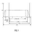
- Fig. 1 is a graph indicating the amplitude vs. frequency characteristics of an ideal NTSC signal;
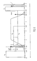
- Fig. 2 is a graph indicating the baseband spectrum of an actual NTSC signal;
- Fig. 3(a) and 3(b) describe front end filtering in an NTSC receiver;
- Fig. 4 is a block diagram of a modem suitable for implementing the invention;
- Fig. 5 is a block diagram of one embodiment of the encoder shown in Fig. 4;
- Fig. 6 is a graph indicating an embodiment of a carrier configuration in accordance with the invention;
- Fig. 7 is a block diagram of an embodiment of a circuit which incorporates the functions of the serial to parallel converter and encoder shown in Fig. 4;
- Figs. 8 and 9 are block diagrams illustrating an adaptive MCM system comprising the invention.
- Fig. 1 illustrates an ideal NTSC signal characteristic showing the placement of the picture, chroma and sound carriers within the signal bandwidth. Fig. 2 describes the baseband spectrum of a color-bar NTSC signal, where an interval between two harmonic numbers represents a frequency interval equal to (the product of the harmonic number and) the horizontal scanning frequency (or the line-scanning rate), fh, and the
harmonic number 0 corresponds to the picture carrier. As can be seen from the Fig. 2, the spectrum of the color-bar NTSC signal is simply a line spectrum. This is true because a color-bar signal has no motion and has periodic components in both luminance and chrominance. It is known that the color-bar signal has a much larger average power than a typical NTSC signal. - In an actual NTSC signal which includes motion, each line frequency component gets "smeared" into clusters of components. For scenes in which the motion is sufficiently slow to perceive the detail of moving objects, it can be safely assumed that less than half the spectral space between the line-frequency harmonics is occupied by energy of significant magnitude. This unoccupied portion of the video signal spectrum may be filled by another signal, which will not be degraded by the presence of NTSC transmission. Thus, it is possible to send an MCM carrier of a much higher power in the interval between the two line-frequency components. Tests have shown that the observed interference of a carrier placed on top of a line-frequency component of an NTSC signal is the same as that of a carrier properly interleaved with the NTSC signal, i.e. placed between two line frequency components with a 14 dB higher power. A properly interleaved carrier not only is less interfering to the NTSC signal, it is also subject to less interference from the NTSC signal. This property is currently used in the "precision-offset" operation of co-channel NTSC stations.
- It has been generally accepted in the industry to implement the NTSC receiver front-end filtering as shown in Figs 3(a) and 3(b). In these figures, all frequencies are indicated with respect to the picture carrier. Fig. 3(a) shows the shape of the receiver IF amplitude response curve for a television receiver, which is well-known as Nyquist shaping. Fig. 3(b) shows the IF filter design simplification, which also provides an attenuation of the upper end of the channel, used mostly in modern receivers. These graphs make it clear that an interfering signal with a higher power can be tolerated by an NTSC receiver in the region below the picture carrier as opposed to the frequencies above the picture carrier. The inventive modulation systems described in the parent applications utilize this property to minimize interference between HDTV and NTSC co-channel signals. The instant invention also utilizes this property.
- In a first embodiment of the invention, incorporating the basic principles of MCM modulation, transmission and reception described in the incorporated references, a carrier level is assigned to each carrier by multiplying each carrier by a respective weighting coefficient. The weights for respective carriers are chosen to configure the MCM signal to provide minimum interference to, and from, an NTSC co-channel signal. An appropriate inverse weighting is provided at the receiver. Such interference is minimized by taking advantage of the multiple carriers conveying the information by eliminating those carriers which are frequency correlated to the luminance, chrominance and sound carriers of the NTSC signal.
- Figure 4 is a block diagram of an MCM modem adapted for use in accordance with the invention. In the
modulator 120, a digital input bit stream (TX Data) is parallelized into n parallel data streams using the serial to parallelconverter 10, where n equals the number of carriers used in the MCM signal. The parallel data streams are provided to theencoder 20. The functions of theencoder 20 comprise mapping each of the n parallelized bit streams into complex output symbols and weighting each of the symbols in accordance with respective coefficients derived from a signal reference, i.e. an NTSC signal spectrum. The weighted output symbols from theencoder 20 are passed through an inverse fast fourier transformer (IFFT) 30 where the weighted complex data streams are modulated on respective orthogonal frequency multiplexed carriers using the inverse fast fourier transform. The multiplexed multicarrier signal is then through a digital-to- analog (D/A)converter 40. This output is passed through alowpass filter 50 to remove image frequencies, obtained by the D/A conversion. The output of thelowpass filter 50 then undergoes baseband to RF conversion inconverter 60 and transmission to thedemodulator 130. - At the
demodulator 130, the received RF signal is converted to baseband inconverter 65 and goes through an inverse processing vialow pass filter 60, A/D converter 70, serial toparallel buffer 80, fast fourier transformer (FFT)90,decoder 100, and parallel toserial buffer 110. A more complete MCM receiver would include known additional circuitry such as a timing recovery circuit, equalization, etc., which are not shown in Fig. 4. - As explained above, a more robust yet minimally interfering MCM signal can be generated, for use in a "simulcast" environment, by choosing the frequency spacing of the carriers to be equal to half the NTSC line-scanning rate, fh, which is equal to 7.862 KHz. This implies that the useful time interval on which the
receiver 130 operates is equal to 127.194 usec. An additional signal can be sent during a "guard" interval by the transmitter, which allows the channel response to die down before useful processing is started at the receiver. A 1024 point FFT can be used for example, which implies that there are 1024 carriers, so that the total bandwidth of operation is equal to 8,050,823.168 Hz. A significant number of these carriers will have to be zeroed out however by appropriate weighting in themodulator 20, to operate in a conventional television bandwidth, i.e. 6 MHz. In such a bandwidth, approximately 763 carriers can be sent. Some of these carriers will be zeroed out at frequency regions close to the band-edges and around the picture, chroma and the sound carriers of the NTSC co-channel signal. Also some carriers will be used for timing and carrier recovery as well as for equalization. Depending upon the exact implementation, about 650 to 700 carriers will be available for actual data transmission. If the guard time allowed is 22.8208 usec, for example, then with 695 carriers, 4.5M symbols/sec can be transmitted. - The symbol time is given by the reciprocal of the carrier spacing, while the guard time can be obtained from the typical multipath expected in the terrestrial transmission of the MCM signal.
- Fig. 5 describes a first embodiment of the
encoder 20. Each of the parallel data streams supplied by serial toparallel buffer 10 is encoded into a complex symbol, specified by an appropriate mapping on a QAM constellation, inconstellation mapper 21. Such mapping techniques are known to those skilled in the art and are discussed and/or referred to in the references incorporated herein. Each resulting complex symbol stream is then multiplied by a respective weighting coefficient, cn, n = 1, 1024, inIFFT frame buffer 22, which comprises a plurality of multipliers. The coefficients are derived incoefficient source 23 based upon an arbitrary NTSC spectrum reference which is stored, for example, in a ROM. These coefficients are weighted relative to each other and hence if one coefficient is arbitrarily given a weight of 1, the weights of the rest can be easily calculated using the NTSC spectrum reference. - In this first example, an NTSC spectrum derived from a spectral analysis of a color-bar video input is used to calculate the respective coefficients in
coefficient source 23. Such a spectrum is shown in Fig. 2. - The
coefficient source 23 comprises means for storing a representation of the spectrum and means for deriving coefficients from respective components of the spectrum. Coefficients are derived using means which incorporate known techniques of spectrum analysis discussed in the "Television Engineering Handbook" by Benson (pp. 5.34-5.36), which is incorporated by reference herein. Actual derivation of the coefficients, in accordance with the invention, is based upon the following rules: - For those MCM carriers placed higher in frequency with respect to the picture carrier of the NTSC spectrum, where the carriers are an even multiple of half the line-scanning rate, the coefficients are chosen to have an inverse relationship to the amplitudes of the respective line frequency components of the spectrum as shown, for example, in Fig. 2, i.e. the larger the amplitude of the frequency component, the smaller the weighting coefficient. For carriers placed at an odd multiple of the line-scanning rate, two cases arise. For the case where the chroma is interleaved with the luminance in the spectrum, the coefficients are evaluated such that the inverse relationship described above is maintained. For the case where no chroma signal component is present in the spectrum, a coefficient which is five times the coefficient next to it is used, where the "next" coefficient is arbitrarily defined to be the smaller coefficient among the two adjacent coefficients. This factor of five was mentioned above in connection with test results corresponding to equal visibility of interference for carriers placed at different points in the NTSC spectrum.
- For carriers placed below the picture carrier, the Nyquist shaping (indicated in Fig 3(a)) that is done at a typical NTSC receiver must be taken into account, and therefore two possibilities arise. For carriers to be placed in frequency at an even multiple of the line scanning rate, the coefficients are calculated having an inverse relationship with the line frequency components at that frequency, considering the Nyquist shaped NTSC spectrum. For frequencies placed at an odd multiple of the line-scanning rate, each coefficient is five times the coefficient next to it.
- Using the above rules, the weighting coefficients can be provided which multiply each of the n complex symbol data streams in
IFFT frame buffer 22 to minimize its respective MCM carrier in areas of higher activity within the NTSC reference signal, for example in the portions of the spectrum occupied by the picture, chroma and sound carriers, and maximize its respective carrier in areas least effecting conventional NTSC receivers. As described in the example below, themodulator 120 can thereby provide a shaped MCM signal having a much greater SNR with respect to an NTSC co-channel signal, as compared to conventional wideband digital modulation schemes. - While a color-bar spectrum was used as a reference for deriving the coefficients in the example above, other types of averaged NTSC spectrum references can also be used in accordance with the invention.
- A significant simplification in the weighting process is possible by selecting just five distinct coefficients, four of them corresponding to the four combinations of either the carriers placed above or below the picture carrier or the presence or absence of line frequency components at a given carrier location described above, and a fifth corresponding those portions of the received NTSC spectrum where almost no power is received after the Nyquist filtering in an NTSC receiver. Fig. 6 describes the MCM carriers according to their associated power spectral densities, P, , 2
PL 2 , P3 and P4, reflecting the five coefficients. - The relative amplitudes shown, reflect the "shaping" done by the five coefficients in the
encoder 20 as described above. Using the NTSC reference spectrum as a guide, five distinct coefficients, rather than n coefficients, are selected in a desired relationship to one another and used to shape portions of the MCM spectrum with respect to the NTSC reference signal. In such a system,coefficient source 23 could be a simple memory based look-up table which assigns one of the five coefficients to each of the n parallel complex data streams provided by themapper 21. - The exact frequency ranges used in this example, are shown in Table 1. The power level of P1 relative to the lowest power signal, P4, is shown as X+Y+Z dB. These power levels must be evaluated by interference experiments. In the examples described below, some nominal values for X, Y and Z are assumed, to obtain "conservative" and "aggressive" designs described below.

- The carriers appearing in the portions of the 6MHz spectrum denoted as P1 have the highest power level, reflecting for example the use of the highest of the five coefficients. These portions are placed in areas of the spectrum where little or no signal is seen by the NTSC receiver. A guard band of 0.075MHz is left at the two ends of the 6 MHz spectrum and is assumed to be sufficient due to the severe drop in the power level at the band edges in an MCM transmission scenario.
- P2 and P2 are alternating carriers sent in the frequency regions as shown in Table 1, such that the carriers corresponding to P2 lie exactly between two line-frequency components associated with the co-channel NTSC signal, while the carriers corresponding to P2 lie on top of the line-frequency components. As described above, the carriers associated with P2 can therefore be transmitted at a higher power with the same perceived level of interference as the carriers associated with
PL 2 . This power difference is denoted as Y. Similarly, P3 and P4 also correspond to higher and lower powered alternating carriers. - Using the NTSC reference spectrum as a guideline, no carriers of higher power are transmitted beyond a harmonic number of 145, otherwise, a substantial amount of interference will be seen in the chroma section of the co-channel NTSC signal. However, carriers of the same power as that of P4 are sent on these carriers. The difference in power levels P3 and P4 as compared with P2 and
PL 2 , respectively, indicated as X, is to take into account NTSC receiver Nyquist filter characteristics discussed above, which allow a more powerful interfering signal to be tolerated in the region below the picture carrier. The Nyquist filter characteristic is also shown on the graph of Fig. 6. - Experimental data indicates that X can be any value up to about 12 dB. For the "conservative" example summarized below, a nominal value of about 5 dB can be chosen. In a more "aggressive" design, a value of about 7.5 dB could be used for X. From interference tests done using only a single carrier, Y can be at most about 14 dB. However, since MCM carriers are typically a band of frequencies, the interference effects into NTSC are not known. A nominal value of about 5 dB for Y could be used for a "conservative" design and a value of about 7.5 dB for an "aggressive" design. The value of Z is limited by the adjacent channel interference that can be caused to an adjacent NTSC channel or by the amount of interference into the sound carrier of the NTSC co-channel signal. A value of 2.5 dB for Z is used herein.
- In the example represented by the values of Table 1, 695 carriers are used to transmit data in the MCM signal. The bandwidth fraction is defined as the total nominal bandwidth used by these carriers as a fraction of the total available 6 MHz bandwidth. The sum of these fractions equals 0.91 and represents the utilization of the total available 6 MHz bandwidth which is 5.46 MHz. Apart from the guard band at either end of the spectrum, some bandwidth is also lost near the picture and the sound carrier. In order to provide for the FM baseband requirements of the sound carrier, a 0.2MHz portion is also lost in the region surrounding the sound carrier.
- The following indicates the criteria used to suppress the MCM carriers occurring in the frequencies around the NTSC picture carrier. Again, this suppression is accomplished by the coefficient weighting in the
encoder 20 described above. - For the MCM carriers exactly on top of the line-frequency components associated with the NTSC reference signal, the MCM carriers are not suppressed only if the amplitudes of the corresponding NTSC spectrum are at least 20 dB less in power as compared to the picture carrier. This is done to protect the MCM carriers from the NTSC interference into MCM.
- For the MCM carriers between the NTSC line-frequency components, the space immediately adjacent to the picture carrier is avoided so that any interference from the NTSC signal into the MCM signal is minimal. This space could be used to transmit an unmodulated carrier for frequency synchronization.
- If the nominal bandwidth used in the MCM design is assumed to be 5.46 MHz, we can calculate the raw bit rates that can be transmitted for this bandwidth, for different modulation formats, if all the carriers are assumed to be modulated by the same QAM modulation format. These rates are shown in the Table 2.

- A further improvement in performance can be achieved by assigning different modulation formats to each of the MCM carriers. Thus the extra power available in a given MCM design can be exploited by sending more data, thus trading power for higher bit-rate transmission.
- In the modem embodiment described above, serial to
parallel converter 10 andencoder 20 provided a stream of complex symbols toIFFT 30 which were all mapped in the same format, for example 16 QAM which would achieve a data transmission rate of 18 Mbps. This transmission rate would be increased to 22.5 Mbps if 32 QAM were used however. The effect of different modulation formats for different MCM carriers will be analyzed below. - Table 3 lists the bit-rate possible by using differing modulation formats over each of the different set of MCM carriers with the power levels, Pi,
PH 2 ,PL 2 , P3 and P4.
- Different strategies can be used to get variable bit rates by using different mapping constellations for different MCM carriers.
- In the following examples, the number of points in a constellation, as noted by the numeral prefix, is the key design parameter. It is to be understood that although the constellations are denoted as QAM in these examples, other PAM-PSK constellations could be used with similar results. To obtain the proper reliability, the difference in power levels that can be sent over these carriers must be taken into account. With reference to Fig. 6, the values of X, Y and Z will decide the extra power that can be sent using MCM.
- The following are examples of conservative and aggressive designs.
- For a conservative implementation, the following configuration could be used:
- • Use 16 QAM on P4.
- • Use 64 QAM on
PH 2 , P2 and P3. - • Use 128 QAM on Pi.
- With the above parameters, using the channel coding strategy with a (216,192) RS code and a 0.9 rate trellis code, for example, the total available payload is 19 Mbps. Currently proposed digital HDTV signals anticipate a payload of 18.5 Mbps. Using this design the invention would therefore yield an additional data rate of 0.5 Mbps, which could be used to transmit a secondary audio program.
- In this design, the power assumptions made above are maintained. With this design, the power corresponding to all carriers other than P4 is improved. Since, the coverage area is decided by the weakest link in the chain, the bits sent on the MCM carriers with a power level given by P4 must be protected. Thus, the following design could be used:
- • Use 8 QAM on P4.
- • Use 64 QAM on P2 and P3.
- • Use 128 QAM on P1 and
PH 2 . - The total available payload is 17.34 Mbps. From comments made in the previous section, it is clear that the bit streams sent using the MCM carriers with
power levels PL 2, P3 and P4 have the same reliability. In this case, the bit streams sent using the MCM carriers with power levels P1 have a higher reliability than the bit streams related toPH 2 . A higher payload can be obtained by using 256 QAM for MCM carriers using Pi, but the higher constellation size may cause significant degradations in actual modem implementation. It is assumed in this example that Z=0 dB, i.e., P1 and P2 have the same power level and hence the same reliability. - A further design for the transmission of conventional quality digital television (as opposed to HDTV), which is also referred to in the industry as digital NTSC, will need only a small subset of all the carriers available. It is assumed herein that an approximate payload of 7.5 Mbps is required for transmission of the entire digital NTSC signal. The following strategy can therefore be used:
- ·
Use 2 QAM on P4. - · Use 8 QAM on P2 and P3.
- · Use 32 QAM on P1 and
PH 2 . - Fig. 7 describes a preferred embodiment of a circuit which incorporates and performs, in a prioritized manner, the functions of serial to parallel
converter 10 andencoder 20. This circuit can be used in themodulator 120, to implement modulation format strategies such as those described in the designs described above. - As described in the '383 and '006 applications, the serial data provided by the channel coder can consist of higher and lower priority data. The respective priorities can be identified as part of the respective data words and therefore easily separated after channel coding. Therefore, since it is well within the skill of those knowledgeable in the art to separate the serial data into a higher priority (HP) serial stream and a lower priority (LP) serial stream, the following explanation will assume that this has been done in the channel coder and that the HP and LP streams are being provided to the serial to parallel converter shown in Fig. 7.
- The circuit of Fig. 7 has the additional advantage therefore, of directing input data having different priorities, to different groups of carriers.
- Fig. 7 actually shows only one section of the circuit (for HP data) and it is to be understood that an identical circuit, optimized for LP data, is also part of Fig. 7. Indeed, if more than two priorities exist in the input serial data, a separate section as described, could be used for each of them. In the following discussion of Fig. 7, only the operation of the circuit with regard to HP data will be explained in detail. LP data is handled in the same manner in a duplicate circuit (not shown) which forms part of Fig. 7.
- HP serial data and associated clock information is provided to an input of serial to
parallel shift register 200 which provides a symbol having a number of bits, S, for each serial HP data word. The number of bits, S, given to each symbol is directly related to the modulation format (i.e. the bit length QAM implemented in map table 250) used to generate each of the n complex symbols.Shift register 200 is controlled by modulo S counter 220 which counts the HP clock pulses, i.e. HP input bits. - A look-up address table 240 controls counter 220 by providing for each of the n inputs to IFFT 30 (corresponding to the n carriers as described above), a value for S. As described in the "conservative" design above, for example, those complex symbols to be modulated on carriers corresponding to P4 would be mapped using 16 QAM. Those corresponding to pH , P2 and P3 would be mapped using 64 QAM, and those corresponding to P1 would be mapped using 128 QAM. The circuit of Fig. 7 can accomplish this selective mapping.
- It will be assumed that for a particular design, selected N inputs to the
IFFT 30, and therefore corresponding selected N carriers, will be supplied with complex symbols derived for the HP data. These N inputs/carriers could be contiguous or spectrally separated (i.e. in different P groups). The modulo N counter 230 sequentially provides an input address K, representing a count from 0 to N, to address table 240. Stored in address table 240 are values of S for each value of K. This address table is preprogrammed in ROM (for example) to follow a particular design. Since each value of S is related to a chosen modulation format (mapping), such a table for the "conservative" design would reflect bit lengths S for each address K (i.e. for each of the carriers in the respective P groups). The value of S selected for the Kth count is loaded intocounter 220 which counts S clock pulses and then generates a carry. At thispoint shift register 200 contains S bits of HP data. The output of theshift register 200, combined with the value of S provided by table 240 at the selected address K, is used to address map table 250. Map table 250 is a look-up table in which actual complex symbol values are stored and which performs the mapping of the parallel output ofshift register 200 into a complex symbol corresponding to an SQAM format. - Coefficient table 260 is a look-up table which corresponds to the
coefficient source 23 described in Fig. 5.Multiplexer 290 acts as a switch to permit addressing of the coefficient table to be a function of input A, the address signal K fromcounter 230. In this example, we will assume that the address signal for coefficient table 260 is the address signal K from counter 230 (input A). An adaptive approach utilizing input B, will be discussed below. - Assuming that the coefficient table 260 has been set up to correlate a number of coefficient weights to be assigned to each of the N map table complex symbol outputs, the address signal K will select the appropriate coefficient which will be multiplied with the corresponding complex symbol in
multiplier 300. Each weighted complex symbol is loaded intoIFFT buffer 270 at an address which is also determined by address signal K. - The loading of the weighted complex symbol is controlled by the carry signal which occurs after each group of S bits has been input (i.e.
counter 220 = S). The carry signal also increments counter 230 which generates the next address K. - When all of the IFFT buffer 270 locations have been filled with the N weighted complex symbols, and a corresponding IFFT buffer in the LP section (not shown) have also been filled, the contents of both buffers are sent to
IFFT 30. - Although not described in detail, it is to be understood that the invention comprises a demodulator which incorporates means for decoding MCM signals modulated using the circuits of Figs. 5 and 7. Such a decoding means would comprise complementary coefficient inverse weighting look-up tables and, if necessary (i.e. to decode signals from a Fig. 7 type circuit) correlated map and S select tables.
- Figs. 8 and 9 illustrate another embodiment of the invention which functions in an adaptive way by using, for example, the actual NTSC co-channel signal as the NTSC spectrum reference, instead of the color bar spectrum discussed above, in conjunction with, for example, the
MCM modulator 120. - As shown in Fig. 8, a highly
directional receiving antenna 150 is used by the HDTV "simulcast"transmitter site 155, to receive the instantaneous NTSCco-channel signal broadcast 160. - As shown in Fig. 9, the
modulator 120 at thetransmitter site 155 subjects the received spectrum of the NTSC co-channel toFFT analysis 170, and the results of this spectral analysis is then used as the NTSC reference for deriving the weighting coefficients as described above. These coefficients are then fed to the encoder ofMCM modulator 120. The coefficients can thus be updated periodically to adapt to changes in the interference characteristics presented by the NTSC co-channel signal. The update rate depends upon the trade-off that exists between the coefficient information transmitted and the improvement in performance. - The adaptive embodiment described above can also be used with the circuit of Fig. 7.
Multiplexer 290 permits the use of an adaptive mode (input B) as an alternative to the non-adaptive mode described above. - In the non-adaptive mode, the coefficient table 260 contains a set of pre-programmed coefficients correlated to the complex symbols associated with each MCM carrier. These coefficients, as stated above, are determined based upon a spectral analysis of an NTSC reference signal (i.e. a color bar spectrum). In the non-adaptive mode, the coefficient table is addressed by signal K from counter 230 to apply shaping to each of the N complex symbols from map table 250 in sequence. In the adaptive mode, the coefficient table 260 must be programmable (i.e. RAM). Input B, when selected by the SEL signal, periodically loads the coefficients calculated by
FFT analysis 170 into coefficient table 260. Themultiplexer 290 is then switch back to input A and addressing occurs in the same manner as in the adaptive mode. A similar programmable coefficient table would be present in a demodulator present in anHDTV receiver 175, in accordance with the invention, and would similarly be able to configure itself using an identical FFT analysis performed on the received NTSC co-channel signal. - The FCC has stated that eventually it expects to phase out NTSC broadcasting in favour of the "simulcast" HDTV broadcasts, as more NTSC receivers are replaced by HDTV receivers in the home. Currently proposed "simulcast" systems provide varying methods by which interference to the NTSC co-channel signals is avoided. All of these methods reduce in some manner the robustness of the "simulcast" signal. Using the instant invention however, once an NTSC co-channel signal is removed from service, the coefficients can easily be changed so that the "simulcast" signal can be free of unnecessary modification, without requiring the purchase of a new HDTV receiver or new broadcasting equipment. In fact, using the invention, should the newly available co-channel be assigned to another HDTV signal, or other type of communication service signal, coefficients could easily be derived to provide, based on this new signal, similar anti-interference advantages.
- While certain representative embodiments and details have been shown for the purpose of illustrating the present invention, it will be apparent to persons skilled in the art that various modifications may be made in the disclosed systems without departing from the spirit and the scope of the disclosed invention.
Claims (15)
Applications Claiming Priority (2)
| Application Number | Priority Date | Filing Date | Title |
|---|---|---|---|
| US854177 | 1992-03-20 | ||
| US07/854,177 US5291289A (en) | 1990-11-16 | 1992-03-20 | Method and apparatus for transmission and reception of a digital television signal using multicarrier modulation |
Publications (3)
| Publication Number | Publication Date |
|---|---|
| EP0571005A2 true EP0571005A2 (en) | 1993-11-24 |
| EP0571005A3 EP0571005A3 (en) | 1994-08-10 |
| EP0571005B1 EP0571005B1 (en) | 1999-06-02 |
Family
ID=25317946
Family Applications (1)
| Application Number | Title | Priority Date | Filing Date |
|---|---|---|---|
| EP93200706A Expired - Lifetime EP0571005B1 (en) | 1992-03-20 | 1993-03-11 | Method and system for transmission and reception of a digital television signal using multicarrier modulation |
Country Status (6)
| Country | Link |
|---|---|
| US (1) | US5291289A (en) |
| EP (1) | EP0571005B1 (en) |
| JP (1) | JP3415875B2 (en) |
| AU (1) | AU667512B2 (en) |
| CA (1) | CA2091863C (en) |
| DE (1) | DE69325126T2 (en) |
Cited By (6)
| Publication number | Priority date | Publication date | Assignee | Title |
|---|---|---|---|---|
| EP0742654A1 (en) * | 1995-05-10 | 1996-11-13 | France Telecom | Multicarrier digital signal reducing co-channel interference with an analog television signal, and receiver for such a signal |
| WO1998034381A1 (en) * | 1997-01-16 | 1998-08-06 | Nokia Telecommunications Oy | Data transmission method and radio system |
| EP1919094A1 (en) * | 2006-10-30 | 2008-05-07 | Mitsubishi Electric Information Technology Centre Europe B.V. | Method and device for transmission during guard period |
| AU2011203042B2 (en) * | 2005-07-27 | 2012-02-23 | Qualcomm Atheros, Inc. | Managing spectra of modulated signals in a communication network |
| US8416887B2 (en) | 2005-07-27 | 2013-04-09 | Qualcomm Atheros, Inc | Managing spectra of modulated signals in a communication network |
| US8654635B2 (en) | 2003-11-24 | 2014-02-18 | Qualcomm Incorporated | Medium access control layer that encapsulates data from a plurality of received data units into a plurality of independently transmittable blocks |
Families Citing this family (90)
| Publication number | Priority date | Publication date | Assignee | Title |
|---|---|---|---|---|
| USRE39890E1 (en) | 1991-03-27 | 2007-10-23 | Matsushita Electric Industrial Co., Ltd. | Communication system |
| USRE40241E1 (en) | 1991-03-27 | 2008-04-15 | Matsushita Electric Industrial Co., Ltd. | Communication system |
| US5600672A (en) | 1991-03-27 | 1997-02-04 | Matsushita Electric Industrial Co., Ltd. | Communication system |
| USRE42643E1 (en) | 1991-03-27 | 2011-08-23 | Panasonic Corporation | Communication system |
| US5892879A (en) | 1992-03-26 | 1999-04-06 | Matsushita Electric Industrial Co., Ltd. | Communication system for plural data streams |
| US6724976B2 (en) | 1992-03-26 | 2004-04-20 | Matsushita Electric Industrial Co., Ltd. | Communication system |
| US6728467B2 (en) * | 1992-03-26 | 2004-04-27 | Matsushita Electric Industrial Co., Ltd. | Communication system |
| US5802241A (en) * | 1992-03-26 | 1998-09-01 | Matsushita Electric Industrial Co., Ltd. | Communication system |
| US7158577B1 (en) | 1992-03-26 | 2007-01-02 | Matsushita Electric Industrial Co., Ltd. | Communication system |
| USRE38513E1 (en) | 1992-03-26 | 2004-05-11 | Matsushita Electric Industrial Co., Ltd. | Communication system |
| US7894541B2 (en) * | 1992-03-26 | 2011-02-22 | Panasonic Corporation | Communication system |
| CN1032099C (en) | 1992-03-26 | 1996-06-19 | 松下电器产业株式会社 | Communication Systems |
| US5465396A (en) | 1993-01-12 | 1995-11-07 | Usa Digital Radio Partners, L.P. | In-band on-channel digital broadcasting |
| EP0617531A1 (en) * | 1993-03-25 | 1994-09-28 | Matsushita Electric Industrial Co., Ltd. | Multiresolution transmission system |
| US5371548A (en) * | 1993-07-09 | 1994-12-06 | Cable Television Laboratories, Inc. | System for transmission of digital data using orthogonal frequency division multiplexing |
| WO1995007576A2 (en) * | 1993-09-10 | 1995-03-16 | Amati Communications Corporation | Digital sound broadcasting using a dedicated control channel |
| US5588022A (en) * | 1994-03-07 | 1996-12-24 | Xetron Corp. | Method and apparatus for AM compatible digital broadcasting |
| FR2719382B1 (en) * | 1994-05-02 | 1996-05-31 | Thomson Csf | Discrete radar detection method and implementation system. |
| US5557612A (en) * | 1995-01-20 | 1996-09-17 | Amati Communications Corporation | Method and apparatus for establishing communication in a multi-tone data transmission system |
| AU695092B2 (en) | 1994-06-02 | 1998-08-06 | Amati Communications Corporation | Method and apparatus for coordinating multi-point-to-point communications in a multi-tone data transmission system |
| US5625651A (en) * | 1994-06-02 | 1997-04-29 | Amati Communications, Inc. | Discrete multi-tone data transmission system using an overhead bus for synchronizing multiple remote units |
| US5572249A (en) * | 1994-07-07 | 1996-11-05 | Philips Electronics North America Corporation | Method and apparatus for optimal NTSC rejection filtering and transmitter and receiver comprising same |
| IL114471A0 (en) * | 1994-07-12 | 1996-01-31 | Usa Digital Radio Partners L P | Method and system for simultaneously broadcasting and analog signals |
| US5956624A (en) * | 1994-07-12 | 1999-09-21 | Usa Digital Radio Partners Lp | Method and system for simultaneously broadcasting and receiving digital and analog signals |
| US6282683B1 (en) * | 1994-09-26 | 2001-08-28 | Adc Telecommunications, Inc. | Communication system with multicarrier telephony transport |
| US6334219B1 (en) | 1994-09-26 | 2001-12-25 | Adc Telecommunications Inc. | Channel selection for a hybrid fiber coax network |
| USRE42236E1 (en) | 1995-02-06 | 2011-03-22 | Adc Telecommunications, Inc. | Multiuse subcarriers in multipoint-to-point communication using orthogonal frequency division multiplexing |
| US7280564B1 (en) | 1995-02-06 | 2007-10-09 | Adc Telecommunications, Inc. | Synchronization techniques in multipoint-to-point communication using orthgonal frequency division multiplexing |
| US5651010A (en) * | 1995-03-16 | 1997-07-22 | Bell Atlantic Network Services, Inc. | Simultaneous overlapping broadcasting of digital programs |
| US5532748A (en) * | 1995-03-31 | 1996-07-02 | Matsushita Electric Corporation Of America | Hybrid analog/digital television transmission system |
| US5784683A (en) * | 1995-05-16 | 1998-07-21 | Bell Atlantic Network Services, Inc. | Shared use video processing systems for distributing program signals from multiplexed digitized information signals |
| GB9510127D0 (en) * | 1995-05-20 | 1995-08-02 | West End System Corp | CATV Data transmission system |
| AU727079B2 (en) * | 1996-01-24 | 2000-11-30 | Adc Telecommunications, Incorporated | Communication system with multicarrier telephony transport |
| DE19609909A1 (en) * | 1996-03-14 | 1997-09-18 | Deutsche Telekom Ag | Method and system for OFDM multicarrier transmission of digital radio signals |
| JPH09321721A (en) * | 1996-05-27 | 1997-12-12 | Sony Corp | Transmission method, transmission device, reception method, and reception device |
| US5796842A (en) | 1996-06-07 | 1998-08-18 | That Corporation | BTSC encoder |
| US8908872B2 (en) | 1996-06-07 | 2014-12-09 | That Corporation | BTSC encoder |
| US6757913B2 (en) | 1996-07-15 | 2004-06-29 | Gregory D. Knox | Wireless music and data transceiver system |
| JPH1066039A (en) * | 1996-08-23 | 1998-03-06 | Sony Corp | Communication method, transmitting device, transmitting method, receiving device, and receiving method |
| WO1998009385A2 (en) | 1996-08-29 | 1998-03-05 | Cisco Technology, Inc. | Spatio-temporal processing for communication |
| DE19638654A1 (en) * | 1996-09-20 | 1998-03-26 | Siemens Ag | Digital message transmission method |
| US6175550B1 (en) * | 1997-04-01 | 2001-01-16 | Lucent Technologies, Inc. | Orthogonal frequency division multiplexing system with dynamically scalable operating parameters and method thereof |
| US6549242B1 (en) * | 1997-04-04 | 2003-04-15 | Harris Corporation | Combining adjacent TV channels for transmission by a common antenna |
| US7110370B2 (en) * | 1997-10-22 | 2006-09-19 | Texas Instruments Incorporated | Method and apparatus for coordinating multi-point to point communications in a multi-tone data transmission system |
| US7733966B2 (en) * | 1997-12-30 | 2010-06-08 | Summit Technology Systems, Lp | System and method for space diversified linear block interleaving |
| EP2154854B1 (en) | 1998-01-06 | 2012-03-07 | Mosaid Technologies Incorporated | Multicarrier modulation system with variable symbol rates |
| US6944139B1 (en) * | 1998-03-27 | 2005-09-13 | Worldspace Management Corporation | Digital broadcast system using satellite direct broadcast and terrestrial repeater |
| US6433835B1 (en) | 1998-04-17 | 2002-08-13 | Encamera Sciences Corporation | Expanded information capacity for existing communication transmission systems |
| US20030140351A1 (en) * | 1998-04-17 | 2003-07-24 | Hoarty W. Leo | Cable television system compatible bandwidth upgrade using embedded digital channels |
| US20030112370A1 (en) * | 2001-12-18 | 2003-06-19 | Chris Long | Adaptive expanded information capacity for communications systems |
| DE19958210C2 (en) | 1999-12-02 | 2003-08-21 | Fraunhofer Ges Forschung | Device and method for generating a transmission sequence and device and method for determining an information word from a received transmission sequence |
| US6788349B2 (en) | 2000-04-12 | 2004-09-07 | Her Majesty Of Queen In Right Of Canada, As Respresented By The Minister Of Industry | Method and system for broadcasting a digital data signal within an analog TV signal using Orthogonal Frequency Division Multiplexing |
| EP1277317A2 (en) * | 2000-04-22 | 2003-01-22 | Atheros Communications, Inc. | Multi-carrier communication systems employing variable ofdm-symbol rates and number of carriers |
| WO2002102007A1 (en) * | 2001-06-09 | 2002-12-19 | Samsung Electronics Co., Ltd | Method and apparatus for rearranging codeword sequence in a communication system |
| US7962162B2 (en) * | 2001-08-07 | 2011-06-14 | At&T Intellectual Property Ii, L.P. | Simulcasting OFDM system having mobile station location identification |
| US7180942B2 (en) * | 2001-12-18 | 2007-02-20 | Dotcast, Inc. | Joint adaptive optimization of soft decision device and feedback equalizer |
| US20030219085A1 (en) * | 2001-12-18 | 2003-11-27 | Endres Thomas J. | Self-initializing decision feedback equalizer with automatic gain control |
| US7738551B2 (en) * | 2002-03-18 | 2010-06-15 | International Business Machines Corporation | System and method for processing a high definition television (HDTV) image |
| US7756421B2 (en) * | 2002-10-03 | 2010-07-13 | Ciena Corporation | Electrical domain compensation of non-linear effects in an optical communications system |
| US7382984B2 (en) * | 2002-10-03 | 2008-06-03 | Nortel Networks Limited | Electrical domain compensation of optical dispersion in an optical communications system |
| WO2004075469A2 (en) * | 2003-02-19 | 2004-09-02 | Dotcast Inc. | Joint, adaptive control of equalization, synchronization, and gain in a digital communications receiver |
| JP2005136770A (en) * | 2003-10-31 | 2005-05-26 | Leader Electronics Corp | Digital broadcast signal generator |
| US7292198B2 (en) * | 2004-08-18 | 2007-11-06 | Ruckus Wireless, Inc. | System and method for an omnidirectional planar antenna apparatus with selectable elements |
| US7696946B2 (en) | 2004-08-18 | 2010-04-13 | Ruckus Wireless, Inc. | Reducing stray capacitance in antenna element switching |
| US8031129B2 (en) | 2004-08-18 | 2011-10-04 | Ruckus Wireless, Inc. | Dual band dual polarization antenna array |
| US7880683B2 (en) | 2004-08-18 | 2011-02-01 | Ruckus Wireless, Inc. | Antennas with polarization diversity |
| US7362280B2 (en) * | 2004-08-18 | 2008-04-22 | Ruckus Wireless, Inc. | System and method for a minimized antenna apparatus with selectable elements |
| US7193562B2 (en) | 2004-11-22 | 2007-03-20 | Ruckus Wireless, Inc. | Circuit board having a peripheral antenna apparatus with selectable antenna elements |
| US7498996B2 (en) * | 2004-08-18 | 2009-03-03 | Ruckus Wireless, Inc. | Antennas with polarization diversity |
| US7965252B2 (en) * | 2004-08-18 | 2011-06-21 | Ruckus Wireless, Inc. | Dual polarization antenna array with increased wireless coverage |
| US7652632B2 (en) * | 2004-08-18 | 2010-01-26 | Ruckus Wireless, Inc. | Multiband omnidirectional planar antenna apparatus with selectable elements |
| CN1934750B (en) * | 2004-11-22 | 2012-07-18 | 鲁库斯无线公司 | Circuit board having a peripheral antenna apparatus with selectable antenna elements |
| US7358912B1 (en) * | 2005-06-24 | 2008-04-15 | Ruckus Wireless, Inc. | Coverage antenna apparatus with selectable horizontal and vertical polarization elements |
| US7646343B2 (en) * | 2005-06-24 | 2010-01-12 | Ruckus Wireless, Inc. | Multiple-input multiple-output wireless antennas |
| US7893882B2 (en) | 2007-01-08 | 2011-02-22 | Ruckus Wireless, Inc. | Pattern shaping of RF emission patterns |
| US7639106B2 (en) | 2006-04-28 | 2009-12-29 | Ruckus Wireless, Inc. | PIN diode network for multiband RF coupling |
| US20070293178A1 (en) * | 2006-05-23 | 2007-12-20 | Darin Milton | Antenna Control |
| US20080008255A1 (en) * | 2006-07-10 | 2008-01-10 | Raj Kumar Jain | Multiple rate architecture for wireline communication system |
| US8488691B2 (en) * | 2008-10-08 | 2013-07-16 | Qualcomm Incorporated | Adaptive loading for orthogonal frequency division multiplex (OFDM) communication systems |
| US8217843B2 (en) | 2009-03-13 | 2012-07-10 | Ruckus Wireless, Inc. | Adjustment of radiation patterns utilizing a position sensor |
| US8698675B2 (en) | 2009-05-12 | 2014-04-15 | Ruckus Wireless, Inc. | Mountable antenna elements for dual band antenna |
| US9282274B2 (en) * | 2009-06-22 | 2016-03-08 | Entropic Communications, Llc | System and method for reducing intra-channel interference |
| US9407012B2 (en) | 2010-09-21 | 2016-08-02 | Ruckus Wireless, Inc. | Antenna with dual polarization and mountable antenna elements |
| US8756668B2 (en) | 2012-02-09 | 2014-06-17 | Ruckus Wireless, Inc. | Dynamic PSK for hotspots |
| US10186750B2 (en) | 2012-02-14 | 2019-01-22 | Arris Enterprises Llc | Radio frequency antenna array with spacing element |
| US9634403B2 (en) | 2012-02-14 | 2017-04-25 | Ruckus Wireless, Inc. | Radio frequency emission pattern shaping |
| US9092610B2 (en) | 2012-04-04 | 2015-07-28 | Ruckus Wireless, Inc. | Key assignment for a brand |
| US9570799B2 (en) | 2012-09-07 | 2017-02-14 | Ruckus Wireless, Inc. | Multiband monopole antenna apparatus with ground plane aperture |
| HK1220050A1 (en) | 2013-03-15 | 2017-04-21 | Ruckus Wireless, Inc. | Low-band reflector for dual band directional antenna |
| US11108433B2 (en) * | 2018-11-30 | 2021-08-31 | Intel Corporation | Single side band transmission over a waveguide |
Family Cites Families (14)
| Publication number | Priority date | Publication date | Assignee | Title |
|---|---|---|---|---|
| US2636937A (en) * | 1949-04-01 | 1953-04-28 | Rca Corp | Signal separating circuit for color television |
| US4525847A (en) * | 1982-11-10 | 1985-06-25 | Paradyne Corporation | QAM encoder |
| US4780884A (en) * | 1986-03-03 | 1988-10-25 | American Telephone And Telegraph Company, At&T Bell Laboratories | Suppressed double-sideband communication system |
| FR2609228B1 (en) * | 1986-12-24 | 1989-12-01 | France Etat | METHOD OF DIGITAL BROADCASTING IN TELEVISION CHANNELS |
| US5134464A (en) * | 1990-11-16 | 1992-07-28 | North American Philips Corporation | Method and apparatus for the transmission and reception of a multicarrier digital television signal |
| KR0139527B1 (en) * | 1988-10-21 | 1998-07-01 | 아르레뜨 다낭제 | Transmitter, transmission method and receiver |
| US5022053A (en) * | 1989-04-10 | 1991-06-04 | At&T Bell Laboratories | Data communications with alternation of signaling constellations |
| JPH0687541B2 (en) * | 1989-06-22 | 1994-11-02 | シャープ株式会社 | Quadrature amplitude modulation wave demodulator |
| US5056117A (en) * | 1989-08-07 | 1991-10-08 | At&T Bell Laboratories | Decision feedback equalization with trellis coding |
| EP0500704A1 (en) * | 1989-11-06 | 1992-09-02 | General Electric Company | Signal processing apparatus for a widescreen television system |
| JPH03203416A (en) * | 1989-12-29 | 1991-09-05 | Sharp Corp | Automatic equalizer and orthogonal amplitude modem |
| ATE139660T1 (en) * | 1990-03-30 | 1996-07-15 | Digi Media Vision Ltd | TRANSMIT AND RECEIVE IN AN INTERFERENTIAL INTERFERENCE ENVIRONMENT |
| US5113412A (en) * | 1990-06-08 | 1992-05-12 | General Datacomm, Inc. | Method and apparatus for mapping an eight dimensional constellation of a convolutionally coded communication system |
| US5127021A (en) * | 1991-07-12 | 1992-06-30 | Schreiber William F | Spread spectrum television transmission |
-
1992
- 1992-03-20 US US07/854,177 patent/US5291289A/en not_active Expired - Fee Related
-
1993
- 1993-03-10 AU AU35124/93A patent/AU667512B2/en not_active Ceased
- 1993-03-11 EP EP93200706A patent/EP0571005B1/en not_active Expired - Lifetime
- 1993-03-11 DE DE69325126T patent/DE69325126T2/en not_active Expired - Fee Related
- 1993-03-17 CA CA002091863A patent/CA2091863C/en not_active Expired - Fee Related
- 1993-03-22 JP JP06203193A patent/JP3415875B2/en not_active Expired - Fee Related
Cited By (14)
| Publication number | Priority date | Publication date | Assignee | Title |
|---|---|---|---|---|
| EP0742654A1 (en) * | 1995-05-10 | 1996-11-13 | France Telecom | Multicarrier digital signal reducing co-channel interference with an analog television signal, and receiver for such a signal |
| FR2734109A1 (en) * | 1995-05-10 | 1996-11-15 | France Telecom | MULTI-CHANNEL DIGITAL SIGNAL LIMITING COCAN INTERFERENCE WITH AN ANALOGUE TELEVISION SIGNAL AND RECEPTION OF SUCH A SIGNAL |
| EP2154812A2 (en) | 1995-05-10 | 2010-02-17 | France Telecom | Multi-carrier digital signal transmitter reducing co-channel interference with an analogue television signal |
| EP2262195A2 (en) | 1995-05-10 | 2010-12-15 | France Telecom | Transmitter and receiver for a multicarrier digital signal reducing co-channel interference with an analog television signal |
| EP2262195A3 (en) * | 1995-05-10 | 2012-01-18 | France Telecom | Transmitter and receiver for a multicarrier digital signal reducing co-channel interference with an analog television signal |
| WO1998034381A1 (en) * | 1997-01-16 | 1998-08-06 | Nokia Telecommunications Oy | Data transmission method and radio system |
| US6606296B1 (en) | 1997-01-16 | 2003-08-12 | Nokia Corporation | Data transmission method and radio system |
| US9013989B2 (en) | 2003-11-24 | 2015-04-21 | Qualcomm Incorporated | Medium access control layer that encapsulates data from a plurality of received data units into a plurality of independently transmittable blocks |
| US8654635B2 (en) | 2003-11-24 | 2014-02-18 | Qualcomm Incorporated | Medium access control layer that encapsulates data from a plurality of received data units into a plurality of independently transmittable blocks |
| AU2011203042B2 (en) * | 2005-07-27 | 2012-02-23 | Qualcomm Atheros, Inc. | Managing spectra of modulated signals in a communication network |
| US8416887B2 (en) | 2005-07-27 | 2013-04-09 | Qualcomm Atheros, Inc | Managing spectra of modulated signals in a communication network |
| CN101197617B (en) * | 2006-10-30 | 2013-02-06 | 三菱电机株式会社 | Transmission method in a wireless telecommunication system including at least a base station intended to communicate with terminals |
| US7817602B2 (en) | 2006-10-30 | 2010-10-19 | Mitsubishi Electric Corporation | Transmission method in a wireless telecommunication system including at least a base station intended to communicate with terminals |
| EP1919094A1 (en) * | 2006-10-30 | 2008-05-07 | Mitsubishi Electric Information Technology Centre Europe B.V. | Method and device for transmission during guard period |
Also Published As
| Publication number | Publication date |
|---|---|
| CA2091863A1 (en) | 1993-09-21 |
| JPH0654306A (en) | 1994-02-25 |
| AU3512493A (en) | 1993-09-23 |
| EP0571005A3 (en) | 1994-08-10 |
| JP3415875B2 (en) | 2003-06-09 |
| DE69325126D1 (en) | 1999-07-08 |
| DE69325126T2 (en) | 1999-11-18 |
| CA2091863C (en) | 2003-05-06 |
| EP0571005B1 (en) | 1999-06-02 |
| US5291289A (en) | 1994-03-01 |
| AU667512B2 (en) | 1996-03-28 |
Similar Documents
| Publication | Publication Date | Title |
|---|---|---|
| US5291289A (en) | Method and apparatus for transmission and reception of a digital television signal using multicarrier modulation | |
| EP0497395B1 (en) | Method and apparatus for the transmission and reception of a multicarrier digital television signal | |
| US5243629A (en) | Multi-subcarrier modulation for hdtv transmission | |
| US5282019A (en) | Method and apparatus for the transmission and reception of a multicarrier digital television signal | |
| US5521943A (en) | COFDM combined encoder modulation for digital broadcasting sound and video with PSK, PSK/AM, and QAM techniques | |
| US7843803B2 (en) | Orthogonal frequency division multiplex modem circuit | |
| KR100207974B1 (en) | Method and apparatus for multiplex code modulation with unequal error protection | |
| KR101368506B1 (en) | New frame and signalling pattern structure for multi-carrier systems | |
| EP0553252B1 (en) | Co-channel interference reduction system for digital high definition television | |
| US5214501A (en) | Method and apparatus for the transmission and reception of a multicarrier high definition television signal | |
| Wu et al. | Digital television terrestrial broadcasting | |
| US7197276B2 (en) | Downstream adaptive modulation in broadband communications systems | |
| EP0649257A2 (en) | Transmission system minimizing interference in digital transmission | |
| AU735773B2 (en) | System for the transmission of high-rate value-added services by terrestrial broadcasting | |
| JPH11511623A (en) | Method of transmitting digital and analog modulated radio and / or television broadcast signals together | |
| Paiement | Evaluation of single carrier and multi-carrier modulation techniques for digital ATV terrestrial broadcasting | |
| KR20030092660A (en) | OFDM Transmitter capable of improving the quality of receiving and a method processing OFDM signal thereof | |
| JP3112576B2 (en) | Digital transmission system and digital modulation transceiver | |
| EP0588542B1 (en) | Multiple QAM digital television signal encoder | |
| Gledhill | OFDM for digital terrestrial television | |
| KR20050027564A (en) | Apparatus and methof for transmitting/receiving multicast data in a multicast orthogonal frequency division multiple communication system | |
| Drury | Broadcasting by satellites | |
| Mondal et al. | TV White Spectrum for Wireless Broadband Internet Connectivity (WBIC) | |
| Mondal et al. | TV White Spectrum for Wireless Broadband Internet Connectivity (WBIC): A theoretical analysis of utilizing TV White Spectrum for Wireless Broadband Internet Connectivity (WBIC) on the basis of availability in the perspective of Bangladesh | |
| JP2001053716A (en) | Radio transmission system, radio transmitting method, transmitter and receiver |
Legal Events
| Date | Code | Title | Description |
|---|---|---|---|
| PUAI | Public reference made under article 153(3) epc to a published international application that has entered the european phase |
Free format text: ORIGINAL CODE: 0009012 |
|
| AK | Designated contracting states |
Kind code of ref document: A2 Designated state(s): DE ES FR GB IT SE |
|
| PUAL | Search report despatched |
Free format text: ORIGINAL CODE: 0009013 |
|
| AK | Designated contracting states |
Kind code of ref document: A3 Designated state(s): DE ES FR GB IT SE |
|
| 17P | Request for examination filed |
Effective date: 19950210 |
|
| 17Q | First examination report despatched |
Effective date: 19970407 |
|
| GRAG | Despatch of communication of intention to grant |
Free format text: ORIGINAL CODE: EPIDOS AGRA |
|
| RAP3 | Party data changed (applicant data changed or rights of an application transferred) |
Owner name: KONINKLIJKE PHILIPS ELECTRONICS N.V. |
|
| GRAG | Despatch of communication of intention to grant |
Free format text: ORIGINAL CODE: EPIDOS AGRA |
|
| GRAH | Despatch of communication of intention to grant a patent |
Free format text: ORIGINAL CODE: EPIDOS IGRA |
|
| GRAH | Despatch of communication of intention to grant a patent |
Free format text: ORIGINAL CODE: EPIDOS IGRA |
|
| GRAA | (expected) grant |
Free format text: ORIGINAL CODE: 0009210 |
|
| AK | Designated contracting states |
Kind code of ref document: B1 Designated state(s): DE ES FR GB IT SE |
|
| PG25 | Lapsed in a contracting state [announced via postgrant information from national office to epo] |
Ref country code: SE Free format text: THE PATENT HAS BEEN ANNULLED BY A DECISION OF A NATIONAL AUTHORITY Effective date: 19990602 Ref country code: IT Free format text: LAPSE BECAUSE OF FAILURE TO SUBMIT A TRANSLATION OF THE DESCRIPTION OR TO PAY THE FEE WITHIN THE PRESCRIBED TIME-LIMIT;WARNING: LAPSES OF ITALIAN PATENTS WITH EFFECTIVE DATE BEFORE 2007 MAY HAVE OCCURRED AT ANY TIME BEFORE 2007. THE CORRECT EFFECTIVE DATE MAY BE DIFFERENT FROM THE ONE RECORDED. Effective date: 19990602 Ref country code: ES Free format text: THE PATENT HAS BEEN ANNULLED BY A DECISION OF A NATIONAL AUTHORITY Effective date: 19990602 |
|
| REF | Corresponds to: |
Ref document number: 69325126 Country of ref document: DE Date of ref document: 19990708 |
|
| ET | Fr: translation filed | ||
| PLBE | No opposition filed within time limit |
Free format text: ORIGINAL CODE: 0009261 |
|
| STAA | Information on the status of an ep patent application or granted ep patent |
Free format text: STATUS: NO OPPOSITION FILED WITHIN TIME LIMIT |
|
| 26N | No opposition filed | ||
| REG | Reference to a national code |
Ref country code: GB Ref legal event code: IF02 |
|
| PGFP | Annual fee paid to national office [announced via postgrant information from national office to epo] |
Ref country code: FR Payment date: 20030328 Year of fee payment: 11 |
|
| PGFP | Annual fee paid to national office [announced via postgrant information from national office to epo] |
Ref country code: GB Payment date: 20030331 Year of fee payment: 11 |
|
| PGFP | Annual fee paid to national office [announced via postgrant information from national office to epo] |
Ref country code: DE Payment date: 20030515 Year of fee payment: 11 |
|
| PG25 | Lapsed in a contracting state [announced via postgrant information from national office to epo] |
Ref country code: GB Free format text: LAPSE BECAUSE OF NON-PAYMENT OF DUE FEES Effective date: 20040311 |
|
| PG25 | Lapsed in a contracting state [announced via postgrant information from national office to epo] |
Ref country code: DE Free format text: LAPSE BECAUSE OF NON-PAYMENT OF DUE FEES Effective date: 20041001 |
|
| GBPC | Gb: european patent ceased through non-payment of renewal fee |
Effective date: 20040311 |
|
| PG25 | Lapsed in a contracting state [announced via postgrant information from national office to epo] |
Ref country code: FR Free format text: LAPSE BECAUSE OF NON-PAYMENT OF DUE FEES Effective date: 20041130 |
|
| REG | Reference to a national code |
Ref country code: FR Ref legal event code: ST |