EP0572250A1 - Procédé de commande pour affichage à cristaux liquides - Google Patents
Procédé de commande pour affichage à cristaux liquides Download PDFInfo
- Publication number
- EP0572250A1 EP0572250A1 EP93304112A EP93304112A EP0572250A1 EP 0572250 A1 EP0572250 A1 EP 0572250A1 EP 93304112 A EP93304112 A EP 93304112A EP 93304112 A EP93304112 A EP 93304112A EP 0572250 A1 EP0572250 A1 EP 0572250A1
- Authority
- EP
- European Patent Office
- Prior art keywords
- pixels
- video signals
- screen
- sample
- half side
- Prior art date
- Legal status (The legal status is an assumption and is not a legal conclusion. Google has not performed a legal analysis and makes no representation as to the accuracy of the status listed.)
- Granted
Links
- 239000004973 liquid crystal related substance Substances 0.000 title claims abstract description 77
- 239000011159 matrix material Substances 0.000 claims description 7
- 230000000750 progressive effect Effects 0.000 claims description 4
- 210000002858 crystal cell Anatomy 0.000 description 19
- 238000010586 diagram Methods 0.000 description 15
- 102000034099 Shq1 Human genes 0.000 description 9
- 108091019659 Shq1 Proteins 0.000 description 9
- 101100421449 Caenorhabditis elegans shn-1 gene Proteins 0.000 description 6
- 238000010276 construction Methods 0.000 description 5
- 230000000694 effects Effects 0.000 description 3
- 239000005357 flat glass Substances 0.000 description 3
- 238000005070 sampling Methods 0.000 description 3
- 238000000034 method Methods 0.000 description 2
- 238000012986 modification Methods 0.000 description 2
- 230000004048 modification Effects 0.000 description 2
- 239000004988 Nematic liquid crystal Substances 0.000 description 1
- 239000003990 capacitor Substances 0.000 description 1
- 238000004519 manufacturing process Methods 0.000 description 1
- 239000000463 material Substances 0.000 description 1
- 239000010409 thin film Substances 0.000 description 1
Images


Classifications
-
- H—ELECTRICITY
- H04—ELECTRIC COMMUNICATION TECHNIQUE
- H04N—PICTORIAL COMMUNICATION, e.g. TELEVISION
- H04N5/00—Details of television systems
- H04N5/66—Transforming electric information into light information
-
- G—PHYSICS
- G09—EDUCATION; CRYPTOGRAPHY; DISPLAY; ADVERTISING; SEALS
- G09G—ARRANGEMENTS OR CIRCUITS FOR CONTROL OF INDICATING DEVICES USING STATIC MEANS TO PRESENT VARIABLE INFORMATION
- G09G3/00—Control arrangements or circuits, of interest only in connection with visual indicators other than cathode-ray tubes
- G09G3/20—Control arrangements or circuits, of interest only in connection with visual indicators other than cathode-ray tubes for presentation of an assembly of a number of characters, e.g. a page, by composing the assembly by combination of individual elements arranged in a matrix no fixed position being assigned to or needed to be assigned to the individual characters or partial characters
- G09G3/34—Control arrangements or circuits, of interest only in connection with visual indicators other than cathode-ray tubes for presentation of an assembly of a number of characters, e.g. a page, by composing the assembly by combination of individual elements arranged in a matrix no fixed position being assigned to or needed to be assigned to the individual characters or partial characters by control of light from an independent source
- G09G3/36—Control arrangements or circuits, of interest only in connection with visual indicators other than cathode-ray tubes for presentation of an assembly of a number of characters, e.g. a page, by composing the assembly by combination of individual elements arranged in a matrix no fixed position being assigned to or needed to be assigned to the individual characters or partial characters by control of light from an independent source using liquid crystals
- G09G3/3611—Control of matrices with row and column drivers
- G09G3/3685—Details of drivers for data electrodes
- G09G3/3688—Details of drivers for data electrodes suitable for active matrices only
-
- G—PHYSICS
- G09—EDUCATION; CRYPTOGRAPHY; DISPLAY; ADVERTISING; SEALS
- G09G—ARRANGEMENTS OR CIRCUITS FOR CONTROL OF INDICATING DEVICES USING STATIC MEANS TO PRESENT VARIABLE INFORMATION
- G09G3/00—Control arrangements or circuits, of interest only in connection with visual indicators other than cathode-ray tubes
- G09G3/20—Control arrangements or circuits, of interest only in connection with visual indicators other than cathode-ray tubes for presentation of an assembly of a number of characters, e.g. a page, by composing the assembly by combination of individual elements arranged in a matrix no fixed position being assigned to or needed to be assigned to the individual characters or partial characters
- G09G3/34—Control arrangements or circuits, of interest only in connection with visual indicators other than cathode-ray tubes for presentation of an assembly of a number of characters, e.g. a page, by composing the assembly by combination of individual elements arranged in a matrix no fixed position being assigned to or needed to be assigned to the individual characters or partial characters by control of light from an independent source
- G09G3/36—Control arrangements or circuits, of interest only in connection with visual indicators other than cathode-ray tubes for presentation of an assembly of a number of characters, e.g. a page, by composing the assembly by combination of individual elements arranged in a matrix no fixed position being assigned to or needed to be assigned to the individual characters or partial characters by control of light from an independent source using liquid crystals
- G09G3/3611—Control of matrices with row and column drivers
- G09G3/3648—Control of matrices with row and column drivers using an active matrix
-
- G—PHYSICS
- G09—EDUCATION; CRYPTOGRAPHY; DISPLAY; ADVERTISING; SEALS
- G09G—ARRANGEMENTS OR CIRCUITS FOR CONTROL OF INDICATING DEVICES USING STATIC MEANS TO PRESENT VARIABLE INFORMATION
- G09G2310/00—Command of the display device
- G09G2310/02—Addressing, scanning or driving the display screen or processing steps related thereto
- G09G2310/0264—Details of driving circuits
- G09G2310/0297—Special arrangements with multiplexing or demultiplexing of display data in the drivers for data electrodes, in a pre-processing circuitry delivering display data to said drivers or in the matrix panel, e.g. multiplexing plural data signals to one D/A converter or demultiplexing the D/A converter output to multiple columns
Definitions
- the present invention relates generally to a liquid crystal display driving system.
- liquid crystal display panels Because of advantages of small size, light weight and low power consumption, liquid crystal display panels have been adopted on various kinds of displays in recent years. For television video display, high resolution liquid crystal display panels with more than 400 pixels in the vertical direction have been used recently. The liquid crystal has a capacitance and a holding time of written signals is relatively long. Because of this, if an interlace scanning system is adopted, the first and the second fields may be displayed simultaneously, causing a picture to show a shift. Further, if the interlace scanning system is used, it becomes necessary to drive a liquid crystal for each frame with AC power and a conspicuous flickering can result.
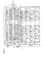
- FIGURE 1 is an explanatory diagram showing a conventional liquid crystal display driving system employing such a double-speed line sequential scanning system with the pixels arranged in a delta shape.
- FIGURE 2 is an explanatory diagram schematically showing Section A encircled in FIGURE 1.
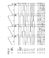
- FIGURE 3 is a timing chart for explaining the operation of this liquid crystal display driving system.
- FIGURE 3(a) shows a video signal
- FIGURE 3(b) shows a start signal (hereinafter referred to as STH pulse)
- FIGURE 3(c) shows a control signal
- FIGURES 3(d) through 3(g) show 1st, 3rd, 2nd and 4th output enable signals (hereinafter referred to as the OE1, OE3, OE2 and OE4 signals), respectively
- FIGURES 3(h) through 3(k) show the state of the gate lines Y11, Y12, Y21 and Y22, respectively
- S/H in FIGURE 3 shows the sample-hold operation and W shows the write operation to the data lines.
- a liquid crystal cell 1 is constructed by filling twist nematic liquid crystal (not shown) between a pair of plate glasses (not shown).
- a common electrode is formed on one of the plate glasses, and gate lines Y (Y11, Y12, Y21, Y22, 7-8) and n pieces of data lines X (X1 through Xn) are formed on the other plate glass, and pixel electrodes (not shown) are formed on the intersections of the gate lines Y and the data lines X.
- Pixels are arranged in the matrix shape at the intersections of the gate lines Y and the data lines X with a thin film transistor (TFT) 2 shown in FIGURE 2 provided to each of the pixels.
- TFT thin film transistor
- a gate signal is supplied to a gate G of each TFT 2 from a gate line controller 3 (hereinafter referred to as the Y driver) through the gate line Y and video signal sampling voltage from a data line driving circuit (hereinafter referred to as the X driver) 4 is supplied to a source S through the data line X, and a drain D is connected to the pixel electrode.
- a liquid crystal capacitance is generated by a liquid crystal 5 which is formed between the pixel electrode and the common electrode. Further, an auxiliary capacitor Cs is provided in parallel with the liquid crystal capacitance.
- the TFT 2 is turned ON by a high level (hereinafter referred to as "H") gate signal from the gate line Y to apply video signal sampling voltage from the data line X to the pixel electrode. As a result, a liquid crystal comprising the pixels is driven to display a picture.
- H high level
- the liquid crystal cell 1 has adopted the delta arrangement of liquid crystal pixels of odd lines and even lines with half of the pixels shifted in the horizontal scanning direction, as shown in FIGURE 1, and the number of lines has been so set that they are sufficient enough to display video signals for one frame of a broadcasting system.
- video signals are supplied simultaneously to two lines of the liquid crystal cell 1 in one horizontal (1H) period and, as shown in FIGURES 3(h) through 3(k), the Y driver 3 makes two gate lines Y11 and Y12, and Y21 and Y22, arranged to "H" sequentially in one horizontal period.
- video signals are written for all pixels in one field period.
- the X driver 4 is composed of a shift register 6, a switch group 7, a sample-hold circuit group 8 and a buffer amplifier group 9.
- the shift register 6 When supplied with the start pulse STH (FIGURE 3(b)) showing the start of the horizontal display period, the shift register 6 outputs ON pulse as the pulses are turned ON sequentially from the first bit at a timing in synchronism with clock CLK. Further, the clock CLK is set to a frequency based on two times of the number of pixels in the horizontal direction of the liquid crystal 1.
- the switches S11, S12 through Snl, Sn2 of the switch group 7 output ON pulse to the sample-hold circuit group 8 under the control of the control signal (FIGURE 3(c)).
- the sample-hold circuit group 8 is composed of 4n pieces of sample-hold circuits SH (SH11 through SH14, SH21 through SH24, . SHn1 through SNn4), and each sample-hold circuit SH samples three primary color video signals R, G and B, which are input through the terminals 11 through 13, at the ON pulse timing from the switch group 7 and holds them.
- the sample-hold circuits SH supply the video signals they are holding to buffer amplifiers B (B11 through B14, B21 through B24, ., Bn1 through Bn4) of the buffer amplifier group 9.
- the buffer amplifier B When turned ON by the OE1, OE2, OE3 and OE4 signals, the buffer amplifier B supplies video signals from the sample-hold circuit SH to the data lines X1 through Xn and executes the write to the pixels of the liquid crystal 1.
- one sample-hold circuit is used for one pixel of the liquid crystal 1, it becomes necessary to perform the write to the pixels within the horizontal blanking period (BLK) because it is needed to stagger the sample-hold period and the write to pixels each other. That is, it is necessary to write video signals from two sample-hold circuits to two pixels of the odd lines and even lines through one data line within one horizontal blanking period. Accordingly, the write to one pixel must be performed in a half time (about 5 ⁇ sec.) of one horizontal blanking period. In such a short time, the write cannot be carried out sufficiently because of a time constant of liquid crystal, and the contrast will become indistinct. For this reason, in FIGURE 1, two sample-hold circuits are provided for one pixel, enabling it to switch the read and write, thus providing a sufficient write time for liquid crystal.
- BLK horizontal blanking period
- sample-hold circuits SH11 and SH12 correspond to the pixels on the first row of the odd lines of the liquid crystal 1
- sample-hold circuits SH13 and SH14 correspond to the pixels on the first row of the even line of the liquid crystal 1.
- sample-hold circuits SHm3 and SHm4 correspond to the m th row of the even lines of the liquid crystal 1.
- the sample-hold circuits SHml and SHm3 hold video signals within the prescribed horizontal scanning period by the ON pulse from the switches Sm1 and Sm2 as shown in FIGURES 3(1) through 3(o)
- the sample-hold circuit SHm2 performs the write to the pixels of the odd lines in the first half of the one horizontal scanning period and the sample-hold circuit SHm4 performs the write to the pixels of the even lines in the latter half of the one horizontal scanning period according to the OE2 and the OE4 signals shown in FIGURES 3(f) and 3(g), respectively
- the sample-hold circuits SHml and SHm4 hold video signals in a prescribed horizontal period
- the sample-hold circuit SHm1 performs the write to the pixels of the odd lines in the first half of one horizontal period
- the sample-hold circuit SHm3 performs the write to the pixels of the even lines in the latter half of one horizontal period.
- the circuits shown in FIGURE 1 are provided with sufficient times for write.
- the size of the liquid crystal display will become large.
- the sample-hold circuits have capacities and if they are integrated, an extremely large space is required and a large size and high cost will result.
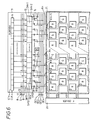
- FIGURE 4 is an explanatory diagram for explaining the method.
- FIGURE 4 shows the construction of the X driver which, differing from the conventional liquid crystal display driving system shown in FIGURE 1, is provided with the sample-hold circuits and the buffer amplifiers corresponding to the pixels of the liquid crystal cell 1 on the one-for-one basis. That is, an X driver 19 is composed of the shift register 6, the sample-hold circuit group 15 and the buffer amplifier group 16. The outputs of all bits of the shift resister 6 are applied to the sample-hold circuits SH-(SH11, SH12, SH21, SH22, dozens SHn1, SHn2) of the sample-hold circuit group 16.
- the sample-hold circuits SH sample the primary color signals R, G and H which are input through the terminals 11 through 13 at the ON pulse timing from the shift register 6 and hold them.
- the outputs of the sample-hold circuits SH11 and SH12 are applied to the data line X1 through the buffer amplifiers B11 and B12, respectively.
- the buffer amplifiers B11, B12, Vietnamese, Bn1, Bn2 are turned ON by the OE1 through the OE4 signals and apply the output of the sample-hold circuit SH to the data lines X.
- FIGURE 4 The operation of a conventional embodiment shown in FIGURE 4 will now be explained with reference to the timing chart, as shown in FIGURE 5.
- the shift register 6 shifts ON pulse by one bit at a time in the clock CLK period and applies them to the sample-hold circuit SH.
- the OE1 signal becomes "H” for the period of 1/4 of 1H from the latter half of the horizontal scanning period and the sample-hold circuit SHp1 applies the holding video signals to the data line Xp through the buffer amplifier Bp1 during this period.
- the Y driver 3 applies "H” gate signal to the gate line Y11 during this period (FIGURE 5(g)) and as a result, the video signals are written for the pixels corresponding to the left side of the first line on the screen of the liquid crystal 1 (FIGURE 5(K)).
- the OE2 signal becomes "H” for the period of H/4 instead of the OE1 signal (FIGURE 5(d)).
- the video signals held by the sample-hold circuit SHp2 is supplied to the data line Xp through the buffer amplifier Bp2.
- the gate line Y12 is kept at "H” (FIGURE 5(h)) by the gate signal from the Y driver 3, and the video signals are written for the pixels corresponding to the left side of the second line on the screen of the liquid crystal 1 (FIGURE 5(1)).
- the sample-hold circuit SHq2 applies the video signals to the data line Xq through the buffer amplifier Bq2 and the video signals are written for the pixels corresponding to the right side of the second line on the screen of the liquid crystal 1 (FIGURE 5(n)). Thereafter, the similar operation is carried out repeatedly.
- the video signals corresponding to the pixels at the left side of the screen, which are sampled and held by the sample-hold circuits SHp1 and SHp2, are written in the H/4 period from the latter half of the horizontal scanning period, respectively after the end of the sample-hold and the video signals corresponding to the right side of the screen, which are sampled and held by the sample-hold circuits SHq1 and SHq2, are written in the H/4 period, respectively after the end of the sample-hold.
- the sample-hold of video signals are carried out by the sample-hold circuits corresponding to the pixels on the one-for-one basis in a sufficient time for writing to the pixels.
- the data line X has a relatively large floating capacitance. Actually, therefore, the video signals from the buffer amplifier B are first held by the data line X and then are written for the pixels. That is, even when the buffer amplifier is turned OFF, the video signals are written for the pixels by the floating capacitance of the data line.
- the OE1 signal is held at "H” and the gate line 21 is also held at "H”.
- the video signals from the sample-hold circuit SHpl are written for the pixels at the left side of the screen as described above.
- the gate line 21 is kept at "H"
- the TFT of the pixels of the third line at the right side of the screen is also turned ON and the video signals being held by the data line Xq of the right side of the screen are written for these pixels.
- the present invention therefore seeks to provide a liquid crystal display driving system which is capable of providing a sufficient time for writing video signals without increasing the circuit size and of improving resolution and providing a natural display.
- a liquid crystal display driving system includes a liquid crystal display unit which has a screen of matrix arrangement comprised of a plurality of pixels, data lines for driving the columns of the pixels and scanning signal lines for driving the rows of the pixels, a circuit for supplying video signal to the pixels through the data lines, a scanning signal line controller for supplying progressive scanning signal to the scanning signal lines, a first sample-hold circuit for holding video signals for the pixels corresponding to odd lows on a first half side of the screen and for supplying the held video signals to the data lines corresponding to the first half side on the screen based on a first output directing signal, a second sample-hold circuit for holding video signals for the pixels corresponding to even lows on the first half side of the screen and for supplying the held video signals to the data lines corresponding to the first half side on the screen based on a second output directing signals, a third sample-hold circuit for holding video signals for the pixels corresponding to odd lows on a second half side of the screen and for supplying the held video signals to
- the liquid crystal display unit has a screen of matrix arrangement comprised of a plurality of pixels, data lines for driving the columns of the pixels, a first set of scanning signal lines for driving the rows of the pixels on a first half side of the screen and a second set of scanning signal lines for driving the rows of the pixels on a second half side of the screen.
- the liquid crystal display unit has a screen of matrix arrangement comprised of a plurality of pixels, a first set of a prescribed scanning signal line and data lines for driving the pixels on a first half side of the screen and a second set of another scanning signal line next to the prescribed scanning signal line and data lines for driving the pixels on a second half side of the screen.
- the first and the second sample-hold means sample and hold the video signals corresponding to the pixels at the first half side of the screen in the first half of the horizontal scanning period
- the third and the fourth sample-hold means sample and hold the video signals corresponding to the pixels at the second half side of the screen in the latter half of the horizontal scanning period.
- FIGURES 6 through 12 The present invention will be described in detail with reference to the FIGURES 6 through 12.
- reference numerals or letters used in FIGURES 1 through 5 will be used to designate like or equivalent elements for simplicity of explanation.
- FIGURES 6, 7 and 8 a first embodiment of the liquid crystal display driving system according to the present invention will be described in detail.
- FIGURE 6 is an explanatory diagram showing the first embodiment of the liquid crystal display driving system of the present invention.
- an X driver 19 is composed of shift register 6, a sample-hold circuit group 15 and a buffer amplifier group 16.
- the shift register 6 has the number of bits which are two times the number of pixels in the horizontal direction and takes in a start signal which is generated at the start timing of the horizontal scanning period and frequency clock CLK which is based on the two times of pixels in the horizontal direction.
- the shift register 6 starts to output ON pulse from the start signal and shifts the ON pulse output bits by one bit at a time in synchronism with the clock CLK.
- the ON pulse from each bit of the shift register 6 is applied to the sample-hold circuit SH (SH11, SH12, SH21, SH22, .
- SHn1, SHn2 of the sample-hold circuit group 15.
- the sample-hold circuits SH11, SH12, SH21, SH22, ., SHn1, SHn2 are applied with color signals R, B, G, R, . and sample and hold these color signals at the timing of the ON pulse from the shift register 6.
- the outputs of the sample-hold circuits SH11, SH12, SH21, SH22, ?? SHn1, SHn2 are applied to the buffer amplifiers B11, B12, B21, B22, Vietnamese, Bn1, Bn2, respectively.
- n are applied with the OE3 signal or the OE4 signal, respectively, and are turned ON when the OE3 or the OE4 signal becomes "H” and apply the outputs of the sample-hold circuits SHq1 and SHq2 to the data lines Xp corresponding to the second half side, e.g., the right side of the liquid crystal cell 21.
- a Y driver 20 has the output terminals corresponding to the number of pixels in the vertical direction of the liquid crystal cell 21 and these output terminals are connected to the gate lines Y11, Y12, Y21, Y22, Vietnamese of the liquid crystal cell 21.
- the Y driver 20 puts the output terminal connected to the gate line Y11 to the "H” level by a timing signal showing the start of the vertical scanning period and thereafter, by shifting the output terminals to make them "H” sequentially in the 1/2 horizontal period, applies the "H” level gate signal to all gate lines Y in one vertical scanning period.
- FIGURE 7 is an explanatory diagram for explaining the arrangement of the pixels of the liquid crystal cell 21, as shown in FIGURE 6.
- the liquid crystal cell 21 has adopted to the delta arrangement where the odd line pixels and the even line pixels are shifted each other by half pixels in the horizontal direction.
- the color filters (not shown) are arranged in order of R, G, B, R, Vietnamese for the odd lines, while they are arrange in order of B, R, G, B, Vietnamese for the even lines.
- FIGURE 8(a) illustrates the video signal
- FIGURE 8(b) illustrates the start signal STH
- FIGURE 8(c) through 8(f) illustrate the OE1, OE2, OE3 and OE4 signals
- FIGURES 8(g) through 8(j) illustrate the gate signals applied to the gate lines Y11, Y12, and Y22
- FIGURES 8(k) and 8(1) illustrate the operations of the sample-hold circuits SHp1 and SHp2, respectively
- FIGURES 8(m) and 8(n) illustrate the operations of the sample-hold circuits SHq1 and SHq2, respectively.
- S/H indicates the sample-hold operation
- W indicates the write operation to the pixels.
- the shift register 6 shifts the ON pulse and applies it to the sample-hold circuit SH.
- the gate line Y11 becomes “L” at the end of the horizontal scanning period
- the OE2 signal become "H” in the horizontal blanking period (FIGURE 8(d)).
- the sample-hold circuit SHp2 applies the holding video signals to the data line Xp through the buffer amplifier Bp2.
- the gate line Y12 also becomes “H”, as shown in FIGURE 8(h) and the video signal applied to the data line Xp are written for the pixels at the left side of the second line.
- the OE2 signal becomes "L” and the sample-hold circuit SHp2 holds the video signals in the first half of the horizontal scanning period.
- the gate line Y12 is kept at "H” during the about 1/2 horizontal scanning period. Therefore, the video signals being kept by the floating capacitance of the data line Xp are continuously written.
- the color signals R, G and B are sampled and kept held by the sample-hold circuits SHq1 and SHq2.
- the OE2 as well as the OE3 signals become "H" (FIGURE 8(e)).
- the sample-hold circuit SHq1 applies the holding video signals to the data line Xq to hold them in its floating capacitance and then, the video signals are written for to the left half pixels as well as the right half pixels connected to the gate line Y12 simultaneously.
- the gate line Y21 becomes "H” only for the 1/2 horizontal scanning period and the video signals of the even lines being held in the floating capacitance of the data line Xq are written for the right half pixels together with the video signals of the odd lines applied to the data line Xp. Thereafter, the same operation is carried out repeatedly.
- the gate lines which are connected to the left half pixels and the right half pixels on the screen are staggered by one line, and the video signals are written for the left half pixels during the period when the video signals corresponding to the right half pixels are sampled and held, while the video signals are written for the right half pixels during the period when the video signals corresponding to the left half pixels are sampled and held, and the sample-hold operation of the sample-hold circuits and the write for the pixels are staggered by using the floating capacitance of the data lines so that the video signals of the preceding line being held in the floating capacitance of the data lines are prevented from being written for the pixels of the next lines.
- the shift register 1 has the number of bits which are two times the number of pixels per line but two registers each of which has the same number of bits as the number of pixels per line may be used to output ON pulses by providing operating clocks of which phases differ by 180 degrees each other to these registers by frequency corresponding to the number of pixels per line.
- the sample-hold circuit group 15 may be divided into two groups of SH11, SH21, . SHn1 and SH12, SH22, Across SHn2 to correspond to the left half and the right half of the screen, respectively.
- the OE2 and the OE3 signals are commonly used and three kinds of OE signals may be used.
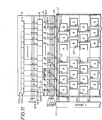
- FIGURE 9 is an explanatory diagram for explaining the second embodiment of the present invention.
- This embodiment differs from the first embodiment shown in FIGURE 6 in that this embodiment uses a liquid crystal cell 30 for the liquid crystal cell 21 and two Y drivers 31 and 32 for the Y driver 20.
- the liquid crystal cell 30 has adopted the delta arrangement using color filters and the pixels of the first through the n the rows are connected to the data lines X1 through Xn (not shown).
- the pixels of the left half lines of the liquid crystal cell 30 are connected to the gate lines Y11, Y12, Y21, Y22, .
- the pixels of the right half lines are connected to the gate lines Y13, Y14, Y23, Y24 .
- the Y driver 31 applies the "H" gate signal to the gate lines Y11, Y12, Y21, Y22, . sequentially
- the Y driver 32 applies the "H” gate signals to the gate lines Y13, Y14, Y23, Y24, .
- FIGURE 10(a) illustrates the video signal
- FIGURE 10(b) illustrates the start signal STH
- FIGURES 10(c) through 10(f) illustrate the OE1 through the OE4 signals, respectively
- FIGURES 10(g) through 10(j) illustrate the gate lines Y11, Y12, Y23, and Y14, respectively
- FIGURES 10(k) through 10(1) illustrate the sample-hold circuits SHp1 and SHp2, respectively
- FIGURES 10(m) and 10(n) illustrate the sample-hold circuits SHq1 and SHq2, respectively.
- the gate lines Y12 and Y13 have changed similarly. Further, the changes of the OE1, OE2 and OE3 signals and the gate lines Y11 and Y12 are the same as those in the first embodiment shown in FIGURE 1.
- the sample-hold and write operations of the video signals to the left half pixels and the right half pixels of the screen are the same as the first embodiment shown in FIGURE 6.
- the gate line Y14 becomes "H" simultaneously when the OE4 signal becomes "H".
- the right half pixels and the left half pixels of the screen a re driven by different gate lines.
- FIGURES 11 and 12 are explanatory diagrams for explaining the third embodiment of the present invention.
- a liquid crystal cell 41 has adopted the delta arrangement and the data lines X1 through Xn are connected to the pixels of the first through the n th rows.
- a TFT 42 is formed for the left half pixels of the liquid crystal cell 41 and a TFT 43 is formed for the right half pixels.
- the gates of TFT 43 of the odd lines are connected to the gate lines Yj2 and the gates of TFT 43 of the even lines are connected to the gate lines Y(j+1)1. That is, the left half pixels and the right half pixels of the screen are driven by the gate lines which are staggered by one line.
- a Y driver 45 supplies the "H" level gate signal to the gate lines Y11 and Y12, . sequentially.
- the present invention is not limited to the embodiments described above.
- the liquid crystal display panel of the delta arrangement having color filters was explained in the embodiments described above.
- the present invention can provide an extremely preferable liquid crystal display driving system. That is, the liquid crystal display driving system according to the present invention has such an effect that a sufficient write time is obtained without increasing the circuit size and resolution can be improved, thus providing a natural display.
Landscapes
- Engineering & Computer Science (AREA)
- Theoretical Computer Science (AREA)
- Physics & Mathematics (AREA)
- Crystallography & Structural Chemistry (AREA)
- Computer Hardware Design (AREA)
- General Physics & Mathematics (AREA)
- Chemical & Material Sciences (AREA)
- Signal Processing (AREA)
- Multimedia (AREA)
- Liquid Crystal Display Device Control (AREA)
- Transforming Electric Information Into Light Information (AREA)
- Control Of Indicators Other Than Cathode Ray Tubes (AREA)
- Preparation Of Compounds By Using Micro-Organisms (AREA)
- Medicines That Contain Protein Lipid Enzymes And Other Medicines (AREA)
- Liquid Crystal (AREA)
Applications Claiming Priority (2)
| Application Number | Priority Date | Filing Date | Title |
|---|---|---|---|
| JP135143/92 | 1992-05-27 | ||
| JP4135143A JPH05328268A (ja) | 1992-05-27 | 1992-05-27 | 液晶表示装置 |
Publications (2)
| Publication Number | Publication Date |
|---|---|
| EP0572250A1 true EP0572250A1 (fr) | 1993-12-01 |
| EP0572250B1 EP0572250B1 (fr) | 1998-08-12 |
Family
ID=15144816
Family Applications (1)
| Application Number | Title | Priority Date | Filing Date |
|---|---|---|---|
| EP93304112A Expired - Lifetime EP0572250B1 (fr) | 1992-05-27 | 1993-05-27 | Procédé de commande pour affichage à cristaux liquides |
Country Status (6)
| Country | Link |
|---|---|
| US (1) | US5745093A (fr) |
| EP (1) | EP0572250B1 (fr) |
| JP (1) | JPH05328268A (fr) |
| KR (1) | KR950013444B1 (fr) |
| CA (1) | CA2097469A1 (fr) |
| DE (1) | DE69320256T2 (fr) |
Cited By (2)
| Publication number | Priority date | Publication date | Assignee | Title |
|---|---|---|---|---|
| EP0737958A3 (fr) * | 1995-04-11 | 1997-12-03 | Sony Corporation | Circuit de commande vidéo pour un dispositif d'affichage |
| CN102903318A (zh) * | 2011-07-29 | 2013-01-30 | 顾晶 | 显示器的子像素排列及其呈现方法 |
Families Citing this family (26)
| Publication number | Priority date | Publication date | Assignee | Title |
|---|---|---|---|---|
| JPH02245793A (ja) * | 1989-03-20 | 1990-10-01 | Hitachi Ltd | マトリックス表示装置 |
| EP0673161B8 (fr) | 1994-03-15 | 2002-05-29 | Canon Kabushiki Kaisha | Système et appareil d'affichage d'informations vidéo |
| JP3518086B2 (ja) * | 1995-09-07 | 2004-04-12 | ソニー株式会社 | 映像信号処理装置 |
| JP2792490B2 (ja) * | 1995-12-20 | 1998-09-03 | 日本電気株式会社 | 液晶表示装置用駆動回路のサンプルホールド回路 |
| JPH1010546A (ja) * | 1996-06-19 | 1998-01-16 | Furon Tec:Kk | 表示装置およびその駆動方法 |
| GB2323958A (en) * | 1997-04-04 | 1998-10-07 | Sharp Kk | Active matrix devices |
| GB9706943D0 (en) * | 1997-04-04 | 1997-05-21 | Sharp Kk | Active matrix device circuits |
| JPH117268A (ja) * | 1997-06-18 | 1999-01-12 | Sony Corp | サンプルホールド回路 |
| JP3386701B2 (ja) * | 1997-10-17 | 2003-03-17 | シャープ株式会社 | 反射型液晶表示装置 |
| US6897855B1 (en) * | 1998-02-17 | 2005-05-24 | Sarnoff Corporation | Tiled electronic display structure |
| JPH11326932A (ja) * | 1998-05-19 | 1999-11-26 | Fujitsu Ltd | 液晶表示装置 |
| US6806862B1 (en) | 1998-10-27 | 2004-10-19 | Fujitsu Display Technologies Corporation | Liquid crystal display device |
| US6498592B1 (en) | 1999-02-16 | 2002-12-24 | Sarnoff Corp. | Display tile structure using organic light emitting materials |
| US6275206B1 (en) * | 1999-03-17 | 2001-08-14 | Intel Corporation | Block mapping based up-sampling method and apparatus for converting color images |
| GB9915572D0 (en) * | 1999-07-02 | 1999-09-01 | Koninkl Philips Electronics Nv | Active matrix liquid crystal display devices |
| US6885366B1 (en) * | 1999-09-30 | 2005-04-26 | Semiconductor Energy Laboratory Co., Ltd. | Display device |
| JP3367099B2 (ja) * | 1999-11-11 | 2003-01-14 | 日本電気株式会社 | 液晶表示装置の駆動回路とその駆動方法 |
| US6702407B2 (en) * | 2000-01-31 | 2004-03-09 | Semiconductor Energy Laboratory Co., Ltd. | Color image display device, method of driving the same, and electronic equipment |
| GB2383462B (en) * | 2001-12-19 | 2004-08-04 | Lg Philips Lcd Co Ltd | Liquid crystal display |
| KR100884993B1 (ko) * | 2002-04-20 | 2009-02-20 | 엘지디스플레이 주식회사 | 액정표시장치 및 그 구동방법 |
| US7095407B1 (en) * | 2003-04-25 | 2006-08-22 | National Semiconductor Corporation | Method and apparatus for reducing noise in a graphics display system |
| TWI268468B (en) * | 2004-04-12 | 2006-12-11 | Himax Tech Ltd | Liquid crystal on silicon panel and driving method thereof |
| US7427201B2 (en) | 2006-01-12 | 2008-09-23 | Green Cloak Llc | Resonant frequency filtered arrays for discrete addressing of a matrix |
| US8232943B2 (en) * | 2006-12-20 | 2012-07-31 | Lg Display Co., Ltd. | Liquid crystal display device |
| WO2008097867A1 (fr) | 2007-02-07 | 2008-08-14 | Green Cloak Llc | Affichages comprenant des structures de piste adressable |
| US8289306B2 (en) * | 2008-06-27 | 2012-10-16 | Sony Corporation | Static retention mode for display panels |
Citations (2)
| Publication number | Priority date | Publication date | Assignee | Title |
|---|---|---|---|---|
| EP0441692A1 (fr) * | 1990-02-06 | 1991-08-14 | Commissariat A L'energie Atomique | Procédé de commande d'un écran matriciel comportant deux parties indépendantes et dispositif pour sa mise en oeuvre |
| EP0461928A2 (fr) * | 1990-06-14 | 1991-12-18 | Sharp Kabushiki Kaisha | Circuit d'attaque d'électrode de colonne pour un dispositif d'affichage |
Family Cites Families (7)
| Publication number | Priority date | Publication date | Assignee | Title |
|---|---|---|---|---|
| US4830460A (en) * | 1987-05-19 | 1989-05-16 | Advanced Interventional Systems, Inc. | Guidance system and method for delivery system for high-energy pulsed ultraviolet laser light |
| US4740786A (en) * | 1985-01-18 | 1988-04-26 | Apple Computer, Inc. | Apparatus for driving liquid crystal display |
| JPS6273294A (ja) * | 1985-09-27 | 1987-04-03 | カシオ計算機株式会社 | 画像表示装置 |
| US4822142A (en) * | 1986-12-23 | 1989-04-18 | Hosiden Electronics Co. Ltd. | Planar display device |
| JPH0654421B2 (ja) * | 1987-12-07 | 1994-07-20 | シャープ株式会社 | マトリクス型液晶表示装置の列電極駆動回路 |
| US5192945A (en) * | 1988-11-05 | 1993-03-09 | Sharp Kabushiki Kaisha | Device and method for driving a liquid crystal panel |
| US5479280A (en) * | 1992-12-30 | 1995-12-26 | Goldstar Co., Ltd. | Active matrix for liquid crystal displays having two switching means and discharging means per pixel |
-
1992
- 1992-05-27 JP JP4135143A patent/JPH05328268A/ja active Pending
-
1993
- 1993-05-27 DE DE69320256T patent/DE69320256T2/de not_active Expired - Fee Related
- 1993-05-27 EP EP93304112A patent/EP0572250B1/fr not_active Expired - Lifetime
- 1993-05-27 KR KR1019930009285A patent/KR950013444B1/ko not_active Expired - Fee Related
- 1993-05-27 US US08/067,831 patent/US5745093A/en not_active Expired - Fee Related
- 1993-05-27 CA CA002097469A patent/CA2097469A1/fr not_active Abandoned
Patent Citations (2)
| Publication number | Priority date | Publication date | Assignee | Title |
|---|---|---|---|---|
| EP0441692A1 (fr) * | 1990-02-06 | 1991-08-14 | Commissariat A L'energie Atomique | Procédé de commande d'un écran matriciel comportant deux parties indépendantes et dispositif pour sa mise en oeuvre |
| EP0461928A2 (fr) * | 1990-06-14 | 1991-12-18 | Sharp Kabushiki Kaisha | Circuit d'attaque d'électrode de colonne pour un dispositif d'affichage |
Non-Patent Citations (2)
| Title |
|---|
| PATENT ABSTRACTS OF JAPAN vol. 14, no. 286 (P-1064)20 June 1990 & JP-A-2 084 685 ( TOSHIBA ) 26 March 1990 * |
| PATENT ABSTRACTS OF JAPAN vol. 14, no. 437 (E-0980)19 September 1990 & JP-A-2 170 784 ( SHARP ) 2 July 1990 * |
Cited By (7)
| Publication number | Priority date | Publication date | Assignee | Title |
|---|---|---|---|---|
| EP0737958A3 (fr) * | 1995-04-11 | 1997-12-03 | Sony Corporation | Circuit de commande vidéo pour un dispositif d'affichage |
| US5936617A (en) * | 1995-04-11 | 1999-08-10 | Sony Corporation | Display apparatus |
| CN102903318A (zh) * | 2011-07-29 | 2013-01-30 | 顾晶 | 显示器的子像素排列及其呈现方法 |
| EP2741277A4 (fr) * | 2011-07-29 | 2014-12-24 | Shenzhen Yunyinggu Technology Co Ltd | Agencement de sous-pixels pour un afficheur et procédé de rendu associé |
| US9418586B2 (en) | 2011-07-29 | 2016-08-16 | Shenzhen Yunyinggu Technology Co., Ltd | Subpixel arrangements of displays and method for rendering the same |
| US9734745B2 (en) | 2011-07-29 | 2017-08-15 | Shenzhen Yunyinggu Technology Co., Ltd | Subpixel arrangements of displays and method for rendering the same |
| US10417949B2 (en) | 2011-07-29 | 2019-09-17 | Shenzhen Yunyinggu Technology Co., Ltd. | Subpixel arrangements of displays and method for rendering the same |
Also Published As
| Publication number | Publication date |
|---|---|
| EP0572250B1 (fr) | 1998-08-12 |
| KR950013444B1 (ko) | 1995-11-08 |
| KR930024480A (ko) | 1993-12-22 |
| CA2097469A1 (fr) | 1993-11-28 |
| US5745093A (en) | 1998-04-28 |
| JPH05328268A (ja) | 1993-12-10 |
| DE69320256T2 (de) | 1999-01-28 |
| DE69320256D1 (de) | 1998-09-17 |
Similar Documents
| Publication | Publication Date | Title |
|---|---|---|
| EP0572250B1 (fr) | Procédé de commande pour affichage à cristaux liquides | |
| US7508479B2 (en) | Liquid crystal display | |
| US6552705B1 (en) | Method of driving flat-panel display device | |
| KR100242443B1 (ko) | 도트 반전 구동을 위한 액정 패널 및 이를 이용한 액정 표시 장치 | |
| JP2937130B2 (ja) | アクティブマトリクス型液晶表示装置 | |
| US6323871B1 (en) | Display device and its driving method | |
| JP3516382B2 (ja) | 液晶表示装置及びその駆動方法並びに走査線駆動回路 | |
| US8232943B2 (en) | Liquid crystal display device | |
| EP0496532B1 (fr) | Dispositif d'affichage à cristaux liquides | |
| US20090189881A1 (en) | Display device | |
| KR920000355B1 (ko) | 디스플레이 패널 구동장치 | |
| KR101082909B1 (ko) | 게이트 구동 방법 및 그 장치와 이를 갖는 표시장치 | |
| US20030107561A1 (en) | Display apparatus | |
| KR100954011B1 (ko) | 표시 장치 | |
| US20040041769A1 (en) | Display apparatus | |
| US8963912B2 (en) | Display device and display device driving method | |
| US5724061A (en) | Display driving apparatus for presenting same display on a plurality of scan lines | |
| KR100992133B1 (ko) | 신호 처리 장치 및 방법 | |
| JP2747583B2 (ja) | 液晶パネルの駆動回路及び液晶装置 | |
| JP2000098334A (ja) | 液晶表示装置 | |
| JP2008151986A (ja) | 電気光学装置、走査線駆動回路および電子機器 | |
| JPH11133934A (ja) | 液晶駆動装置及び液晶駆動方法 | |
| CN1985296A (zh) | 液晶显示设备 | |
| JP4458121B2 (ja) | 液晶表示装置 | |
| KR20070113567A (ko) | 컬럼-게이트 구동부를 구비한 액정 표시장치 및 그 구동방법 |
Legal Events
| Date | Code | Title | Description |
|---|---|---|---|
| PUAI | Public reference made under article 153(3) epc to a published international application that has entered the european phase |
Free format text: ORIGINAL CODE: 0009012 |
|
| 17P | Request for examination filed |
Effective date: 19930622 |
|
| AK | Designated contracting states |
Kind code of ref document: A1 Designated state(s): DE GB NL |
|
| 17Q | First examination report despatched |
Effective date: 19960528 |
|
| GRAG | Despatch of communication of intention to grant |
Free format text: ORIGINAL CODE: EPIDOS AGRA |
|
| GRAG | Despatch of communication of intention to grant |
Free format text: ORIGINAL CODE: EPIDOS AGRA |
|
| GRAH | Despatch of communication of intention to grant a patent |
Free format text: ORIGINAL CODE: EPIDOS IGRA |
|
| GRAH | Despatch of communication of intention to grant a patent |
Free format text: ORIGINAL CODE: EPIDOS IGRA |
|
| GRAA | (expected) grant |
Free format text: ORIGINAL CODE: 0009210 |
|
| AK | Designated contracting states |
Kind code of ref document: B1 Designated state(s): DE GB NL |
|
| PG25 | Lapsed in a contracting state [announced via postgrant information from national office to epo] |
Ref country code: NL Free format text: LAPSE BECAUSE OF FAILURE TO SUBMIT A TRANSLATION OF THE DESCRIPTION OR TO PAY THE FEE WITHIN THE PRESCRIBED TIME-LIMIT Effective date: 19980812 |
|
| REF | Corresponds to: |
Ref document number: 69320256 Country of ref document: DE Date of ref document: 19980917 |
|
| NLV1 | Nl: lapsed or annulled due to failure to fulfill the requirements of art. 29p and 29m of the patents act | ||
| PLBE | No opposition filed within time limit |
Free format text: ORIGINAL CODE: 0009261 |
|
| STAA | Information on the status of an ep patent application or granted ep patent |
Free format text: STATUS: NO OPPOSITION FILED WITHIN TIME LIMIT |
|
| 26N | No opposition filed | ||
| REG | Reference to a national code |
Ref country code: GB Ref legal event code: IF02 |
|
| PGFP | Annual fee paid to national office [announced via postgrant information from national office to epo] |
Ref country code: GB Payment date: 20040526 Year of fee payment: 12 |
|
| PGFP | Annual fee paid to national office [announced via postgrant information from national office to epo] |
Ref country code: DE Payment date: 20040603 Year of fee payment: 12 |
|
| PG25 | Lapsed in a contracting state [announced via postgrant information from national office to epo] |
Ref country code: GB Free format text: LAPSE BECAUSE OF NON-PAYMENT OF DUE FEES Effective date: 20050527 |
|
| PG25 | Lapsed in a contracting state [announced via postgrant information from national office to epo] |
Ref country code: DE Free format text: LAPSE BECAUSE OF NON-PAYMENT OF DUE FEES Effective date: 20051201 |
|
| GBPC | Gb: european patent ceased through non-payment of renewal fee |
Effective date: 20050527 |