EP0572770B1 - Computer training and support table system - Google Patents
Computer training and support table system Download PDFInfo
- Publication number
- EP0572770B1 EP0572770B1 EP93104493A EP93104493A EP0572770B1 EP 0572770 B1 EP0572770 B1 EP 0572770B1 EP 93104493 A EP93104493 A EP 93104493A EP 93104493 A EP93104493 A EP 93104493A EP 0572770 B1 EP0572770 B1 EP 0572770B1
- Authority
- EP
- European Patent Office
- Prior art keywords
- support
- table top
- leg
- support arm
- support arms
- Prior art date
- Legal status (The legal status is an assumption and is not a legal conclusion. Google has not performed a legal analysis and makes no representation as to the accuracy of the status listed.)
- Expired - Lifetime
Links
Images




Classifications
-
- A—HUMAN NECESSITIES
- A47—FURNITURE; DOMESTIC ARTICLES OR APPLIANCES; COFFEE MILLS; SPICE MILLS; SUCTION CLEANERS IN GENERAL
- A47B—TABLES; DESKS; OFFICE FURNITURE; CABINETS; DRAWERS; GENERAL DETAILS OF FURNITURE
- A47B21/00—Tables or desks for office equipment, e.g. typewriters, keyboards
- A47B21/06—Tables or desks for office equipment, e.g. typewriters, keyboards characterised by means for holding, fastening or concealing cables
-
- A—HUMAN NECESSITIES
- A47—FURNITURE; DOMESTIC ARTICLES OR APPLIANCES; COFFEE MILLS; SPICE MILLS; SUCTION CLEANERS IN GENERAL
- A47B—TABLES; DESKS; OFFICE FURNITURE; CABINETS; DRAWERS; GENERAL DETAILS OF FURNITURE
- A47B17/00—Writing-tables
-
- A—HUMAN NECESSITIES
- A47—FURNITURE; DOMESTIC ARTICLES OR APPLIANCES; COFFEE MILLS; SPICE MILLS; SUCTION CLEANERS IN GENERAL
- A47B—TABLES; DESKS; OFFICE FURNITURE; CABINETS; DRAWERS; GENERAL DETAILS OF FURNITURE
- A47B3/00—Folding or stowable tables
-
- A—HUMAN NECESSITIES
- A47—FURNITURE; DOMESTIC ARTICLES OR APPLIANCES; COFFEE MILLS; SPICE MILLS; SUCTION CLEANERS IN GENERAL
- A47B—TABLES; DESKS; OFFICE FURNITURE; CABINETS; DRAWERS; GENERAL DETAILS OF FURNITURE
- A47B87/00—Sectional furniture, i.e. combinations of complete furniture units, e.g. assemblies of furniture units of the same kind such as linkable cabinets, tables, racks or shelf units
- A47B87/002—Combination of tables; Linking or assembling means therefor
-
- A—HUMAN NECESSITIES
- A47—FURNITURE; DOMESTIC ARTICLES OR APPLIANCES; COFFEE MILLS; SPICE MILLS; SUCTION CLEANERS IN GENERAL
- A47B—TABLES; DESKS; OFFICE FURNITURE; CABINETS; DRAWERS; GENERAL DETAILS OF FURNITURE
- A47B13/00—Details of tables or desks
- A47B13/003—Connecting table tops to underframes
-
- A—HUMAN NECESSITIES
- A47—FURNITURE; DOMESTIC ARTICLES OR APPLIANCES; COFFEE MILLS; SPICE MILLS; SUCTION CLEANERS IN GENERAL
- A47B—TABLES; DESKS; OFFICE FURNITURE; CABINETS; DRAWERS; GENERAL DETAILS OF FURNITURE
- A47B3/00—Folding or stowable tables
- A47B2003/008—Folding or stowable tables the underframe parts being stored in recesses in the underside of the table top
-
- A—HUMAN NECESSITIES
- A47—FURNITURE; DOMESTIC ARTICLES OR APPLIANCES; COFFEE MILLS; SPICE MILLS; SUCTION CLEANERS IN GENERAL
- A47B—TABLES; DESKS; OFFICE FURNITURE; CABINETS; DRAWERS; GENERAL DETAILS OF FURNITURE
- A47B2200/00—General construction of tables or desks
- A47B2200/0001—Tops
- A47B2200/0003—Triangular or trapezoidal desk surface to join desks
-
- A—HUMAN NECESSITIES
- A47—FURNITURE; DOMESTIC ARTICLES OR APPLIANCES; COFFEE MILLS; SPICE MILLS; SUCTION CLEANERS IN GENERAL
- A47B—TABLES; DESKS; OFFICE FURNITURE; CABINETS; DRAWERS; GENERAL DETAILS OF FURNITURE
- A47B2200/00—General construction of tables or desks
- A47B2200/0011—Underframes
- A47B2200/002—Legs
- A47B2200/0026—Desks with C-shaped leg
-
- A—HUMAN NECESSITIES
- A47—FURNITURE; DOMESTIC ARTICLES OR APPLIANCES; COFFEE MILLS; SPICE MILLS; SUCTION CLEANERS IN GENERAL
- A47B—TABLES; DESKS; OFFICE FURNITURE; CABINETS; DRAWERS; GENERAL DETAILS OF FURNITURE
- A47B2200/00—General construction of tables or desks
- A47B2200/0035—Tables or desks with features relating to adjustability or folding
- A47B2200/0037—Folding tables whereby each pair of legs and modesty panel are swung against the underside of the desktop
-
- A—HUMAN NECESSITIES
- A47—FURNITURE; DOMESTIC ARTICLES OR APPLIANCES; COFFEE MILLS; SPICE MILLS; SUCTION CLEANERS IN GENERAL
- A47B—TABLES; DESKS; OFFICE FURNITURE; CABINETS; DRAWERS; GENERAL DETAILS OF FURNITURE
- A47B2200/00—General construction of tables or desks
- A47B2200/008—Tables or desks having means for applying electronic or electric devices
- A47B2200/0081—Auxiliary apparatus with electrical connections for office furniture
Definitions
- This invention relates to folding tables. More particularly, it relates to folding tables specially adapted for use with computers and in the computer training of personnel.
- folding tables are well known in the art (DE-A-86 19 937) and some of them have also been developed for being specifically adapted for computers and "more particularly", to computer training (US-A-4,884,513), and other ones forming table systems comprised of special elements (DE-A-92 01 549), the known devices do not satisfy all requirements concerning arrangements permitting an instructor, for example, to employ a master computer connected to a plurality of slaved workstations operated by students.
- the present invention comprises a computer training and support table system provided with a table foldable between a storage configuration and a working configuration comprising a beam having first and second ends, normally horizontal when said table is in its working configuration, comprising first and second substantially identical leg members, each having a pedestal portion normally vertical when said table is in its working configuration, and a pair of spaced, upper and lower parallel support arms extending horizontally from opposite ends of said pedestal portion; means for pivotally securing each of said leg members to a different one of the first and second ends of said beam whereby said support arms are substantially aligned with said beam when the table is in its storage configuration and substantially perpendicular to said beam when the table is in its working configuration.
- the computer training and support table system is provided with a latch between each of the uppermost support arms and the table top, wherein each of said latches comprises a latch plate mounted on the underside of said table top defining a notch therein including a locking detent, a spring loaded locking pawl carried by said uppermost support arm adapted to engage said locking detent when the table is in its working configuration, and release means on said support arm for disengaging said locking pawl from said locking detent.
- the table of the invention comprises a beam 10 in the form of a thin corrugated sheet steel face plate 12 carrying at each end a vertical end plate 14.
- a section of piano hinge 16 is mounted to the end plate 14 at each end of the beam 10 .
- the piano hinge 16 is connected to a C-shaped leg member 18.
- the leg members 18 at each end of the beam 10 are identical but inverted relative to one another.
- Each comprises a vertical pedestal 20 which is substantially rectangular in cross section to provide a hollow internal wiring channel 22 (Fig. 5).
- the inner surface of the pedestal 20, as viewed in Fig. 3, includes a half width door 24 enclosing the wiring channel 22.
- the door 24 abuts a half-width cover 26 over the channel 22.
- the door 24 and cover 26 hinge together by means of interlocking tabs 28.
- An inwardly projecting edge 26a on cover 26 abuts a similar edge 24a on door 24.
- Hooks 28 on the cover and door are encircled by a rubber band 30 which allows the door 24 to be opened but keeps it normally closed.
- Cantilevered outwardly from the pedestal 20 are an upper support arm 32 and a leg 34. Mounted to the bottom of each of the legs 34 is a pair of adjustable feet 36.
- the top edge of the beam 10 carries lengths of piano hinge 38 along its length and the hinge in turn is secured to the bottom surface of a table top 40 (Figs. 2 and 10).
- the table top 40 is substantially rectangular and, as will be seen in Fig. 22, has a honeycomb core 42 covered by surface skins 44 and bounded by edge spars 46.
- the table top 40 is secured to the support arms 32 by a latch mechanism 48 (Fig. 16).
- the latch is characterized by a single knob which releases upon rotation in any direction.
- the latch mechanism is illustrated most clearly in Figs. 16, 17, and 19.
- a latch plate 50 is secured to the table top 40 by means of screws 52.
- the latch plate 50 defines a U-shaped notch 54 which is semi-circular at its base but wider in a direction facing inwardly of the table top.
- the semi-circular portion of the notch 54 is widened to form a pair of diametrically opposed shoulders 56. Only one of the shoulders 56 is used in each latch, however. This permits the same latch plate 50 to be used for either the right hand or the left hand latch member.
- a latch post 58 is mounted on each of the support arms 32 for engagement with the notch 54 of latch plate 50.
- the latch post 58 is substantially cylindrical and has a dual diameter inner bore 60.
- a slot 62 in the side of the latch post 58 extends from its bore 60 to its outer surface.
- the upper end of the latch post 58 includes a disk-like head 64 surmounting a circular slot 66 which mates with the semi-circular portion of the notch 54 in latchplate 50.
- the latch post 58 is secured to the support arm 32 by a screw 68 which is screwed into support arm 32.
- a lockspring 70 Positioned within the bore 60 and above the head of the screw 68 is a lockspring 70 in the form of a cylindrucally wrapped leaf.
- the latch post 58 is prevented from rotating by a pair of recesses 72 on the post which receive a pair of hemispherical bumps 74 on the support arm 32.
- release lever 76 Surrounding the latch post 58 for rotation relative thereto is a release lever 76. As will be seen from Fig. 19, the release lever 76 defines an internal V-shaped camming surface 78 which encloses a lock pawl 80 slidably received within the slot 62 of the latch post 58. Rotation of the release lever 76 in either direction cams the lock pawl 80 inwardly against the force of lockspring 70 so that it is released from engagement with the shoulder 56. The rotation of release lever 76 is limited by a pair of shoulders 82 on either side of each of the bumps 74 on support arm 32.
- a large wire manager 84 may be installed on the beam 10.
- the large wire manager 84 is in the form of a hinged through which extends along the length of the beam 10 as shown in Fig. 8. Its construction is best illustrated in Figs. 10-12.
- Fig. 10 illustrates the manner in which the wire manager 84 is connected to the beam 10.
- the edge of the wire manager 84 is in the form of a narrow horizontal shelf 86 (Fig. 11) which has at each end a spring-loaded latch 88. As the wire manager 84 is pushed against the beam 10, the latch 88 is cammed outwardly by the beam and the flat bottom 90 of the beam bears against the shelf 86 of the wire manager.
- the wire manager 88 also includes at each end a projecting hook member 92 which carries the latch 88.
- the hook member 92 has an inner surface which conforms to the outer surface of the beam 10.
- the upper end of each hook member 92 carries a depending tab 94 (Fig. 12) which engages a hole 96 in the top of the beam 10.
- the wire manager 84 includes a cover 98 mounted on a piano hinge 100. When the cover 98 is closed, the interior of the wire manager 84 communicates with the interior channel 22 of the leg member 18 via a triangular opening 104 as illustrated in Figs. 3 and 11.
- FIG. 9 illustrates the basic table of this invention with a gallery wire manager 102 in place.
- the wire-carrying portion of the gallery wire manager 102 comprises an angled back-wall 104 which rests against the angled surface of the beam 10 and a horizontal floor 106.
- the ends of the trough carry end brackets 108.
- the end brackets 108 are bent to form outwardly extending flanges 110 which screw into the underside of table top 40.
- a pivotable shield panel 114 is connected to the piano hinge 112.
- a coil spring 116 which tends to maintain the shield panel in its upright position. It may then be readily rotated from its normally closed position as illustrated by solid lines in Fig. 14 to an open position as illustrated by the dash-dotted lines in order to receive wires within the trough as necessary.
- a latching strip 118 (Fig. 22).
- Fig. 22 Secured to the underside of each edge of the table top 40 is a latching strip 118 (Fig. 22).
- Fig. 23 illustrates a pair of table tops 40a, 40b joined by a connector 120.
- Each of the table tops 40 includes a depending latching strip 118a, 118b.
- Each of the table tops 40 is spaced above the top of the corresponding support arm 32a, 32b.
- the table edge connector 120 will now be described with particular reference to Figs. 20 and 23. It is formed of plastic and is basically I-shaped having a narrow central portion 122 terminating in widened bases 124, 126. As illustrated in Fig. 20, the connector 120 is shown inverted from its usual condition of use.
- the bases 124, 126 each includes a flat surface which rests against the undersides of the adjoining table tops 40a, 40b and their thickness is such as to fill the gaps between the table tops and their respective support arms 32a, 32b.
- the underside of the top flange of each support arm is engaged by a depending catch 128.
- a resilient plate 130 extends outwardly on both sides of the central portion 122 of the connector 120. It is formed to overlie the latching strip 118 of a table edge and to engage it with a detent 132a, 132b due to its natural resilience. A finger shelf 134 permits disengagement of the table edge.
- the connector 120 When a pair of tables are to be joined, the connector 120 is first inserted into the gap between one table top 40a and its support arm 32a. It is positioned such that the plate 130 is adjacent the aligned latching strips 118. On being so inserted, the detent 132a of the connector is first depressed by, but then snaps into engagement behind, the latching strip 118a as illustrated in Fig. 23. The adjacent table top 36b is then moved into position to engage the remaining latch pairs which thereupon snap into engagement to combine the table tops as illustrated in Fig. 16. When it is desired to disengage the tables, it is merely necessary to pull on finger shelf 134 allowing the tables to be disengaged and the connector 120 to be removed.
- Tables in accordance with this invention may be interconnected by any of a number of differently shaped weges and bridges.
- a table top 40a is connected to a table top 40c via an intermediate bridge 136 in the shape of a quarter sector of a circle.
- the interconnecting bridge 136 carries depending latching strips 118 (Fig. 21) which match those of the table tops.
- a rectangular strap loop 138 is spaced to match the spacing between bases 124, 126 of the connector.
- the connector 120 engages the bridge 136 in the same manner as an adjacent table edge. However, the bases 124, 126 are received within the strap loops 138 rather than in a space defined by the top of a support arm.
- FIG. 18 An additional feature of the invention which is illustrated in Fig. 18 comprises an electronic cart 140 mounted on casters 142 which may be secured beneath a table top or bridge
- One method of securing the cart 140 is by means of a bracket 144 screwed to the underside of the table top or bridge to engage a handle 146 on the top of the cart. In this manner the cart may be readily disengaged when desired so that it may be removed or replaced. Thus, it is an accessory cart.
Landscapes
- Tables And Desks Characterized By Structural Shape (AREA)
Description
- This invention relates to folding tables. More particularly, it relates to folding tables specially adapted for use with computers and in the computer training of personnel.
- While folding tables are well known in the art (DE-A-86 19 937) and some of them have also been developed for being specifically adapted for computers and "more particularly", to computer training (US-A-4,884,513), and other ones forming table systems comprised of special elements (DE-A-92 01 549), the known devices do not satisfy all requirements concerning arrangements permitting an instructor, for example, to employ a master computer connected to a plurality of slaved workstations operated by students.
- Accordingly, it is the object of the present invention to provide a computer training and support table, system which has an improved folding mechanism for storage.
- Therefore, the present invention comprises a computer training and support table system provided with a table foldable between a storage configuration and a working configuration comprising a beam having first and second ends, normally horizontal when said table is in its working configuration, comprising first and second substantially identical leg members, each having a pedestal portion normally vertical when said table is in its working configuration, and a pair of spaced, upper and lower parallel support arms extending horizontally from opposite ends of said pedestal portion; means for pivotally securing each of said leg members to a different one of the first and second ends of said beam whereby said support arms are substantially aligned with said beam when the table is in its storage configuration and substantially perpendicular to said beam when the table is in its working configuration.
- The computer training and support table system is provided with a latch between each of the uppermost support arms and the table top, wherein each of said latches comprises a latch plate mounted on the underside of said table top defining a notch therein including a locking detent, a spring loaded locking pawl carried by said uppermost support arm adapted to engage said locking detent when the table is in its working configuration, and release means on said support arm for disengaging said locking pawl from said locking detent.
- Various modifications of the system claimed in
independent claim 1 are defined in the dependent claims 2 to 11. - The invention will be described in more detail in the following with reference to the Figures of the drawings, in which
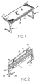
- Fig. 1
- is a perspective view of a table in accordance with this invention;
- Fig. 2
- is a perspective view of the table of Fig. 1 in its folded condition;
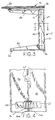
- Fig. 3
- is an enlarged cross section taken substantially along the line 3-3 in Fig. 1;
- Fig. 4
- is an enlarged view of the door of the leg wiring channel, as seen from inside the channel;
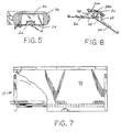
- Fig. 5
- is an enlarged cross section taken substantially along the line 5-5 of Fig. 4;
- Fig. 6
- illustrates the operation of the wiring channel door of Figs. 4 and 5;
- Fig. 7
- is a top plan view of the table of Fig. 1, the top being partially broken away to illustrate the construction;
- Fig. 8
- is a front elevational view of the table of Fig. 7 with a large wire manager installed;
- Fig. 9
- is a front view of a table similar to that of Fig. 1 having a gallery wire manager installed;
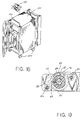
- Fig.10
- is an enlarged perspective detail illustrating the assembly of the beam and wire manager;
- Fig.11
- illustrates the operation of the hinged face of the wire manager;
- Fig.12
- is a detail showing the relationship between the wire manager and the beam;
- Fig.13
- is an exploded view of the gallery, beam, and table top;
- Fig.14
- is an end view of the wire gallery with the right table leg folded;
- Fig.15
- is a front view of a portion of the table and gallery, a portion of the gallery being broken away;
- Fig.16
- is an enlarged cross section taken substantially along the line 16-16 of Fig.1;
- Fig.17
- is a cross section taken substantially along the line 17-17 of Fig.16;
- Fig.18
- is an isometric view of an electronic cart usable with a table of this invention;
- Fig.19
- is a cross section taken substantially along the line 19-19 of Fig.16;
- Fig. 20
- is a perspective view of a table interconnecting device;
- Fig. 21
- is a perspective view of the underside of a bridge of this invention;
- Fig. 22
- is a portion of the table top, partially broken away to illustrate its construction;
- Fig. 23
- is an enlarged cross section taken along the line 23-23 of Fig. 24; and
- Fig. 24
- is a top plan view showing the edges of two rectangular tables joined together and a third table joined by a 90° bridge.
- Referring particularly to Figs. 1-3 and 10, the table of the invention comprises a
beam 10 in the form of a thin corrugated sheetsteel face plate 12 carrying at each end avertical end plate 14. Mounted to theend plate 14 at each end of thebeam 10 is a section ofpiano hinge 16. Thepiano hinge 16 is connected to a C-shaped leg member 18. These parts and the following ones relate to the basic table. - The
leg members 18 at each end of thebeam 10 are identical but inverted relative to one another. Each comprises avertical pedestal 20 which is substantially rectangular in cross section to provide a hollow internal wiring channel 22 (Fig. 5). The inner surface of thepedestal 20, as viewed in Fig. 3, includes ahalf width door 24 enclosing thewiring channel 22. Thedoor 24 abuts a half-width cover 26 over thechannel 22. Thedoor 24 andcover 26 hinge together by means of interlockingtabs 28. An inwardly projecting edge 26a oncover 26 abuts a similar edge 24a ondoor 24. Hooks 28 on the cover and door are encircled by arubber band 30 which allows thedoor 24 to be opened but keeps it normally closed. Cantilevered outwardly from thepedestal 20 are anupper support arm 32 and aleg 34. Mounted to the bottom of each of thelegs 34 is a pair ofadjustable feet 36. - The top edge of the
beam 10 carries lengths ofpiano hinge 38 along its length and the hinge in turn is secured to the bottom surface of a table top 40 (Figs. 2 and 10). Thetable top 40 is substantially rectangular and, as will be seen in Fig. 22, has ahoneycomb core 42 covered bysurface skins 44 and bounded by edge spars 46. - It will now be seen from what has thus far been described that the
individual leg member 18 are hinged relative to thebeam 10 so that they may be folded inwardly from their extended positions to folded positions as illustrated in Fig. 2. It will also be apparent that, by virtue of the lengths ofpiano hinge 38, thetable top 40 may also be hinged downwardly to the folded position illustrated in Fig. 2, thereby providing a neat and compact unit for storage. - The
table top 40 is secured to thesupport arms 32 by a latch mechanism 48 (Fig. 16). The latch is characterized by a single knob which releases upon rotation in any direction. The latch mechanism is illustrated most clearly in Figs. 16, 17, and 19. Alatch plate 50 is secured to thetable top 40 by means ofscrews 52. As will be apparent from Fig. 19, thelatch plate 50 defines aU-shaped notch 54 which is semi-circular at its base but wider in a direction facing inwardly of the table top. The semi-circular portion of thenotch 54 is widened to form a pair of diametrically opposed shoulders 56. Only one of theshoulders 56 is used in each latch, however. This permits thesame latch plate 50 to be used for either the right hand or the left hand latch member. - A
latch post 58 is mounted on each of thesupport arms 32 for engagement with thenotch 54 oflatch plate 50. As will be apparent from Figs. 16 and 19, thelatch post 58 is substantially cylindrical and has a dual diameter inner bore 60. Aslot 62 in the side of thelatch post 58 extends from its bore 60 to its outer surface. The upper end of thelatch post 58 includes a disk-like head 64 surmounting acircular slot 66 which mates with the semi-circular portion of thenotch 54 inlatchplate 50. Thelatch post 58 is secured to thesupport arm 32 by a screw 68 which is screwed intosupport arm 32. Positioned within the bore 60 and above the head of the screw 68 is alockspring 70 in the form of a cylindrucally wrapped leaf. Thelatch post 58 is prevented from rotating by a pair ofrecesses 72 on the post which receive a pair ofhemispherical bumps 74 on thesupport arm 32. - Surrounding the
latch post 58 for rotation relative thereto is arelease lever 76. As will be seen from Fig. 19, therelease lever 76 defines an internal V-shapedcamming surface 78 which encloses alock pawl 80 slidably received within theslot 62 of thelatch post 58. Rotation of therelease lever 76 in either direction cams thelock pawl 80 inwardly against the force oflockspring 70 so that it is released from engagement with theshoulder 56. The rotation ofrelease lever 76 is limited by a pair ofshoulders 82 on either side of each of thebumps 74 onsupport arm 32. - In order to increase the wire carrying-conduit volume ot the table of this invention, a
large wire manager 84 may be installed on thebeam 10. Thelarge wire manager 84 is in the form of a hinged through which extends along the length of thebeam 10 as shown in Fig. 8. Its construction is best illustrated in Figs. 10-12. Fig. 10 illustrates the manner in which thewire manager 84 is connected to thebeam 10. The edge of thewire manager 84 is in the form of a narrow horizontal shelf 86 (Fig. 11) which has at each end a spring-loadedlatch 88. As thewire manager 84 is pushed against thebeam 10, thelatch 88 is cammed outwardly by the beam and theflat bottom 90 of the beam bears against theshelf 86 of the wire manager. Thewire manager 88 also includes at each end a projectinghook member 92 which carries thelatch 88. Thehook member 92 has an inner surface which conforms to the outer surface of thebeam 10. The upper end of eachhook member 92 carries a depending tab 94 (Fig. 12) which engages ahole 96 in the top of thebeam 10. - The
wire manager 84 includes acover 98 mounted on apiano hinge 100. When thecover 98 is closed, the interior of thewire manager 84 communicates with theinterior channel 22 of theleg member 18 via atriangular opening 104 as illustrated in Figs. 3 and 11. - Another accessory which may be used with the basic table of this invention is a gallery wire manager. This accessory provides the dual function of a wire space running the length of the table and a visual shield panel above the top surface of the table to conceal the back of electronic equipment. Fig. 9 illustrates the basic table of this invention with a
gallery wire manager 102 in place. As will be clear from Figs. 13 and 14, the wire-carrying portion of thegallery wire manager 102 comprises an angled back-wall 104 which rests against the angled surface of thebeam 10 and ahorizontal floor 106. The ends of the trough carryend brackets 108. Theend brackets 108 are bent to form outwardly extendingflanges 110 which screw into the underside oftable top 40. - Extending along the bottom edge of the trough of
gallery wire manager 102 is apiano hinge 112. Apivotable shield panel 114, as illustrated in Figs. 13 and 14, is connected to thepiano hinge 112. At each end of theshield panel 114 there is provided acoil spring 116 which tends to maintain the shield panel in its upright position. It may then be readily rotated from its normally closed position as illustrated by solid lines in Fig. 14 to an open position as illustrated by the dash-dotted lines in order to receive wires within the trough as necessary. - Secured to the underside of each edge of the
table top 40 is a latching strip 118 (Fig. 22). When the table of this invention is in its unfolded position as illustrated in Fig. 1, space exists between eachsupport arm 32 and thetable top 36. This space is clearly apparent for example in Fig. 3. This space is utilized to permit the edge to edge connection of tables. The actual connection is effected by a connector 120 as illustrated in Fig. 20. Thus, these parts and the following ones relate to the table connector. - Fig. 23 illustrates a pair of table tops 40a, 40b joined by a connector 120. Each of the table tops 40 includes a depending latching strip 118a, 118b. Each of the table tops 40 is spaced above the top of the
corresponding support arm 32a, 32b. - The table edge connector 120 will now be described with particular reference to Figs. 20 and 23. It is formed of plastic and is basically I-shaped having a narrow
central portion 122 terminating in widenedbases bases respective support arms 32a, 32b. The underside of the top flange of each support arm is engaged by a dependingcatch 128. - A
resilient plate 130 extends outwardly on both sides of thecentral portion 122 of the connector 120. It is formed to overlie the latchingstrip 118 of a table edge and to engage it with adetent 132a, 132b due to its natural resilience. Afinger shelf 134 permits disengagement of the table edge. - When a pair of tables are to be joined, the connector 120 is first inserted into the gap between one
table top 40a and itssupport arm 32a. It is positioned such that theplate 130 is adjacent the aligned latching strips 118. On being so inserted, thedetent 132a of the connector is first depressed by, but then snaps into engagement behind, the latching strip 118a as illustrated in Fig. 23. The adjacent table top 36b is then moved into position to engage the remaining latch pairs which thereupon snap into engagement to combine the table tops as illustrated in Fig. 16. When it is desired to disengage the tables, it is merely necessary to pull onfinger shelf 134 allowing the tables to be disengaged and the connector 120 to be removed. - Tables in accordance with this invention may be interconnected by any of a number of differently shaped weges and bridges. One such arrangement is illustrated in Fig. 24 wherein a
table top 40a is connected to a table top 40c via anintermediate bridge 136 in the shape of a quarter sector of a circle. The interconnectingbridge 136 carries depending latching strips 118 (Fig. 21) which match those of the table tops. Depending from thebridge 136, at either end of each latchingstrip 118 is arectangular strap loop 138. Each pair of strap loops is spaced to match the spacing betweenbases bridge 136 in the same manner as an adjacent table edge. However, thebases strap loops 138 rather than in a space defined by the top of a support arm. - An additional feature of the invention which is illustrated in Fig. 18 comprises an
electronic cart 140 mounted oncasters 142 which may be secured beneath a table top or bridge One method of securing thecart 140 is by means of abracket 144 screwed to the underside of the table top or bridge to engage ahandle 146 on the top of the cart. In this manner the cart may be readily disengaged when desired so that it may be removed or replaced. Thus, it is an accessory cart.
Claims (11)
- A computer training and support table system provided with a table foldable between a storage configuration and a working configuration comprising a beam having first and second ends, normally horizontal when said table is in its working configuration, comprising first and second substantially identical leg members (18), each having a pedestal portion (20) normally vertical when said table is in its working configuration, and a pair of spaced, upper and lower parallel support arms (32) extending horizontally from opposite ends of said pedestal portion (20); means (16) for pivotally securing each of said leg members (18) to a different one of the first and second ends of said beam (10) whereby said support arms (32) are substantially aligned with said beam when the table is in its storage configuration and substantially perpendicular to said beam when the table is in its working configuration, the lowermost support arm of each leg member then functioning as a table leg; and a table top (40) hingedly secured along the top of said beam (10) for rotation between a folded position alongside said support arms (32) when the table is in its storage configuration and a working position resting upon the uppermost support arm of each leg member when the table is in its working configuration, the table comprising a latch (48) between each of the uppermost support arms (32) and the table top (40), wherein each of said latches (48) comprises a latch plate (50) mounted on the underside of said table top (40) defining a notch (54) therein including a locking detent (58), a spring loaded locking pawl (70,80) carried by said uppermost support arm adapted to engage said locking detent (58) when the table is in its working configuration, and release means (76) on said support arm (32) for disengaging said locking pawl (80) from said locking detent (58).
- The table of claim 1 wherein the pedestal portion (20) of each leg member (18) defines a first wiring channel (22) therealong.
- The table of claim 2, wherein said pedestal portion (20) includes a hinged door (24) covering said first wiring channel (22).
- The table of claims 1 - 3 wherein said release means (76) comprises a member rotatable about a substantially vertical axis to disengage said pawl (80) and detent (58) upon rotation in either direction about said axis.
- The table of claim 1 including a wire carrying trough (84) selectively engageable with said beam (10) to form a second wire channel therealong.
- The table of claim 5 wherein said trough (84) includes a hinged cover (98) thereon.
- The table of claim 1 including a gallery wire manager (102) selectively attachable to, and extending along said table top (40) parallel to said beam (10) to form a third wire channel.
- The table of claim 7 wherein said gallery wire manager (102) includes a shield panel (114) hingedly secured thereto for rotation between a position closing said third wire channel and extending above said table top (40) and an open position for access to said third wire channel.
- A computer and training support table system according to any of claims 1 - 8, characterized by further comprising an apparatus (120) for selectively connecting the table top (40a) of the table to a table top (40b) of a further table, the apparatus (120) selectively connecting adjoining edges of the two table tops (40a, 40b), each such edge being supported by a substantially horizontal support arm (32a, 32b), each of said support arms (32a, 32b) and its top defining a space therebetween and the underside of each top carrying a latching member (118) comprising an elongate body member (122); means (124, 126) carried at each end of said body member (122) for extending into both of said spaces and engaging both of said support arms (32a, 32b); and means (130) carried by said body member (122) for resiliently engaging the latching members (118) of both table tops (40a, 40b).
- The computer training and support table system according to claim 9, characterized by a planar bridge member (136) intermediate and adjoining both of the edges of the table and the further table to form an extension of said table tops (40a, 40c), wherein an underside of said bridge member (136) carries the latching member (118) and a pair of socket members (138) adjacent each such edge, and comprising the apparatus (120) for selectively connecting adjoining edges of each table top (40a, 40c), said bridge member (136) comprising the elongate body member (122), said means (124, 126) carried at each end of said body member (122) for extending into both of said space and socket (138), and said means (130) carried by said body member for resiliently engaging the latching members (118) of said table top and said bridge member (136).
- The computer training and support table system according to claim 10, characterized by a storage cart (140) receivable beneath either of said bridge (136) or table top (40a, 40c) and means (144) for releasably securing said cart thereto.
Applications Claiming Priority (2)
| Application Number | Priority Date | Filing Date | Title |
|---|---|---|---|
| US891724 | 1992-06-01 | ||
| US07/891,724 US5337657A (en) | 1992-06-01 | 1992-06-01 | Computer training and support table system |
Publications (3)
| Publication Number | Publication Date |
|---|---|
| EP0572770A2 EP0572770A2 (en) | 1993-12-08 |
| EP0572770A3 EP0572770A3 (en) | 1994-06-22 |
| EP0572770B1 true EP0572770B1 (en) | 1997-01-29 |
Family
ID=25398711
Family Applications (1)
| Application Number | Title | Priority Date | Filing Date |
|---|---|---|---|
| EP93104493A Expired - Lifetime EP0572770B1 (en) | 1992-06-01 | 1993-03-18 | Computer training and support table system |
Country Status (4)
| Country | Link |
|---|---|
| US (1) | US5337657A (en) |
| EP (1) | EP0572770B1 (en) |
| JP (1) | JP2748080B2 (en) |
| DE (1) | DE69307778T2 (en) |
Cited By (2)
| Publication number | Priority date | Publication date | Assignee | Title |
|---|---|---|---|---|
| DE10025338B4 (en) * | 2000-05-23 | 2004-03-18 | Steelcase Werndl Aktiengesellschaft | folding table |
| EP2255694A1 (en) | 2009-05-27 | 2010-12-01 | Steelcase Werndl Aktiengesellschaft | Coupling device, in particular for a furniture adjustment device |
Families Citing this family (57)
| Publication number | Priority date | Publication date | Assignee | Title |
|---|---|---|---|---|
| US6202567B1 (en) | 1994-06-10 | 2001-03-20 | Krueger International, Inc. | Modular table system with cable management |
| US5640912A (en) * | 1995-01-26 | 1997-06-24 | Howe Furniture Corporation | Foldable table with detachable wire management tray |
| NL1000128C2 (en) * | 1995-04-12 | 1996-10-15 | Stork Contiweb | Method for calculating and controlling the elongation of a moving material web and device for applying the method. |
| US5673632A (en) * | 1996-01-03 | 1997-10-07 | Sykes; Christopher C. | Workstation having L-shaped worktop and flat-folding legs |
| JPH11505461A (en) * | 1996-03-15 | 1999-05-21 | ファルコン プロダクツ インコーポレイテッド | Folding table |
| US5927214A (en) * | 1996-06-10 | 1999-07-27 | Ahc Inc. | Flat folding table |
| USD390382S (en) | 1996-06-10 | 1998-02-10 | Hunt Holdings, Inc. | Table |
| US5644994A (en) * | 1996-08-20 | 1997-07-08 | Liang; Chao-C | Folding collapsible table |
| KR200207937Y1 (en) * | 1997-04-04 | 2001-01-15 | 정중희 | Folding desk |
| USD401224S (en) | 1997-06-04 | 1998-11-17 | Rosemount Office Systems, Inc. | Cabling channel for modular office systems |
| JPH11285958A (en) | 1998-04-03 | 1999-10-19 | Toyota Motor Corp | Polishing equipment |
| CA2319779A1 (en) * | 1998-06-05 | 1999-12-09 | Richard Holbrook | Height adjustable workstation |
| DE19837987C2 (en) * | 1998-08-21 | 2002-12-05 | Wilkhahn Wilkening & Hahne | table |
| US6254206B1 (en) | 1999-02-16 | 2001-07-03 | Bretford Manufacturing, Inc. | Wire manager |
| US6282084B1 (en) * | 1999-02-22 | 2001-08-28 | International Business Machines Corporation | Transportable support apparatus for portable computers |
| US6192805B1 (en) * | 1999-05-26 | 2001-02-27 | Haworth, Inc. | Storage bin for workstation |
| US6415723B1 (en) | 1999-05-28 | 2002-07-09 | Krueger International, Inc. | Training table with wire management |
| US6182580B1 (en) | 1999-06-02 | 2001-02-06 | Bretford Manufacturing, Inc. | Mobile connectable furniture, a connector therefor and method of connection |
| USD422813S (en) * | 1999-06-07 | 2000-04-18 | Falcon Products, Inc. | Movable table leg |
| US6314892B1 (en) * | 1999-06-21 | 2001-11-13 | Peter B. Favini | Foldable table |
| US6464625B2 (en) | 1999-06-23 | 2002-10-15 | Robert A. Ganz | Therapeutic method and apparatus for debilitating or killing microorganisms within the body |
| CA2278879C (en) * | 1999-07-26 | 2004-10-19 | Spec Furniture Inc. | Folding leg mechanism |
| EP1217918B1 (en) * | 1999-08-23 | 2003-07-16 | Wilkhahn Wilkening + Hahne Gmbh + Co. | Table with pivotable table-top |
| US6604784B1 (en) * | 1999-10-19 | 2003-08-12 | Krueger International, Inc. | Chair and desk system |
| USD441572S1 (en) | 2000-01-31 | 2001-05-08 | Steelcase Development Inc. | Table |
| USD441224S1 (en) | 2000-03-10 | 2001-05-01 | Steelcase Development Inc. | Table |
| US6448498B1 (en) | 2000-05-02 | 2002-09-10 | Haworth, Inc. | Flexible raceway arrangement for cabling |
| US6848369B1 (en) | 2000-05-02 | 2005-02-01 | Haworth, Inc. | Workstation and power and telecommunication arrangement therefor |
| US6397762B1 (en) | 2000-06-09 | 2002-06-04 | Berco Industries, Inc. | Work table |
| US6647900B1 (en) | 2000-10-06 | 2003-11-18 | Krueger International, Inc. | Folding training table with wire manager pivotably mounted to and between a pair of legs |
| US6336414B1 (en) | 2001-01-31 | 2002-01-08 | Steelcase Development Corp | Table configured for utilities, ganging and storage |
| DE20118884U1 (en) | 2001-10-02 | 2002-02-07 | Cornelius, Christian, 32423 Minden | Tilted, swivel plate |
| CA2418035C (en) * | 2002-01-31 | 2007-09-11 | Krueger International, Inc. | Worksurface support system with power and communication capability and front and rear access covers |
| US6752090B2 (en) * | 2002-03-22 | 2004-06-22 | Innovative Storage Designs, Inc. | Folding desk |
| US6845723B2 (en) * | 2002-10-31 | 2005-01-25 | Hon Technology Inc. | Folding and tilting table |
| US6997115B2 (en) * | 2003-09-19 | 2006-02-14 | Lockwood Joshua C | Steady table |
| US20050263042A1 (en) * | 2004-05-28 | 2005-12-01 | Steelcase Development Corporation | Versatile table system with cable management |
| DE202005012160U1 (en) * | 2005-07-29 | 2005-10-27 | Erich Keller Ag | Furniture piece e.g. working table, for accommodating e.g. processor, has table top arranged on rails, and folding component attached to table top both in closed and open conditions, where component has pivoting section and folding plate |
| US7677184B2 (en) * | 2005-12-15 | 2010-03-16 | Steelcase Development Corporation | Flip top table |
| EP1958537B1 (en) * | 2007-02-19 | 2014-04-30 | Pro-Cord S.p.A. | Nesting and folding table |
| US8091488B2 (en) * | 2007-11-07 | 2012-01-10 | Berco Industries, Inc. | Flip top mechanism for table with nesting capabilities |
| USD604966S1 (en) | 2008-05-23 | 2009-12-01 | Steelcase Inc. | Worksurface assembly |
| US8276523B2 (en) | 2008-05-28 | 2012-10-02 | Steelcase Inc. | Worksurface assembly |
| WO2010083425A2 (en) * | 2009-01-18 | 2010-07-22 | Bretford Manufacturing Inc. | Wire management vanity panel for folding table |
| ES2369327T3 (en) | 2009-05-27 | 2011-11-29 | Steelcase Werndl Aktiengesellschaft | INTERLOCK MECHANISM. |
| US8069795B1 (en) | 2009-06-11 | 2011-12-06 | Krueger International, Inc. | Grip latch and hinge mechanism for a flip table |
| US20110017107A1 (en) * | 2009-07-25 | 2011-01-27 | Wen-Shan Ko | Folding table |
| US8297207B2 (en) * | 2011-01-20 | 2012-10-30 | Choice Industries Corp. | Rapidly assembled office desk |
| US8359983B2 (en) * | 2011-06-02 | 2013-01-29 | Halcon Inc. | Adjustable table apparatus and method |
| USD781626S1 (en) * | 2014-12-19 | 2017-03-21 | Moll Funktionsmobel Gmbh | Office table top |
| US9681763B2 (en) * | 2015-06-01 | 2017-06-20 | Knoll, Inc. | Privacy screen apparatus |
| JP1557542S (en) * | 2015-10-19 | 2016-08-29 | ||
| US9723919B1 (en) * | 2016-02-09 | 2017-08-08 | Symbiote, Inc. | Combination foldable and adjustable workstation |
| US11122886B1 (en) | 2020-05-13 | 2021-09-21 | Halcon Corp. | Adjustable table apparatus and method |
| USD1023624S1 (en) | 2021-08-16 | 2024-04-23 | AMQ Solutions, LLC | Collapsible workstation |
| USD1023627S1 (en) | 2021-08-16 | 2024-04-23 | AMQ Solutions, LLC | Workstation |
| US11974663B2 (en) * | 2022-09-29 | 2024-05-07 | Gain-Ping Co., Ltd. | Folding table |
Family Cites Families (17)
| Publication number | Priority date | Publication date | Assignee | Title |
|---|---|---|---|---|
| US489369A (en) * | 1893-01-03 | Folding table | ||
| US2836475A (en) * | 1956-06-20 | 1958-05-27 | Elton L Sapp | Connected tables |
| US3805710A (en) * | 1972-05-03 | 1974-04-23 | A Leshem | Folding table |
| JPS50118021A (en) * | 1974-03-04 | 1975-09-16 | ||
| CH600826A5 (en) * | 1976-04-29 | 1978-06-30 | Fritschi Albert | |
| AU2431077A (en) * | 1976-04-30 | 1978-10-19 | Dowty Seals Ltd | Seals and gaskets |
| CA1211490A (en) * | 1982-10-27 | 1986-09-16 | Innovative Metal, Inc. C/O/B/A Kinetics Furniture | Powered desk |
| JPS59177165A (en) * | 1983-03-25 | 1984-10-06 | Hitachi Cable Ltd | Paint applicator for enameled wire |
| JPS61191386A (en) * | 1985-02-20 | 1986-08-26 | 蛇の目ミシン工業株式会社 | Computer sewing machine |
| SE8600186D0 (en) * | 1986-01-16 | 1986-01-16 | Euroscan Ab | MACHINE AND LIKE MOUNTING MACHINE |
| DE3720639A1 (en) * | 1987-06-23 | 1989-01-05 | Eggersmann Planmoebel | OFFICE WORKPLACE |
| US4884513A (en) * | 1988-03-01 | 1989-12-05 | Herman Miller, Inc. | Work environment system |
| US5094174A (en) * | 1989-02-07 | 1992-03-10 | Steelcase Inc. | Modular furniture |
| JPH03195314A (en) * | 1989-12-25 | 1991-08-26 | Toshiba Corp | Operating disc |
| CH681948A5 (en) * | 1990-10-10 | 1993-06-30 | Syntech Sa | |
| US5205223A (en) * | 1991-04-18 | 1993-04-27 | Steelcase Inc. | Folding table |
| DE9201549U1 (en) * | 1992-02-08 | 1992-03-26 | Kusch & Co Sitzmöbelwerke KG, 5789 Hallenberg | Table system in modular construction |
-
1992
- 1992-06-01 US US07/891,724 patent/US5337657A/en not_active Expired - Fee Related
-
1993
- 1993-03-18 EP EP93104493A patent/EP0572770B1/en not_active Expired - Lifetime
- 1993-03-18 DE DE69307778T patent/DE69307778T2/en not_active Expired - Fee Related
- 1993-06-01 JP JP5168316A patent/JP2748080B2/en not_active Expired - Fee Related
Cited By (2)
| Publication number | Priority date | Publication date | Assignee | Title |
|---|---|---|---|---|
| DE10025338B4 (en) * | 2000-05-23 | 2004-03-18 | Steelcase Werndl Aktiengesellschaft | folding table |
| EP2255694A1 (en) | 2009-05-27 | 2010-12-01 | Steelcase Werndl Aktiengesellschaft | Coupling device, in particular for a furniture adjustment device |
Also Published As
| Publication number | Publication date |
|---|---|
| JP2748080B2 (en) | 1998-05-06 |
| EP0572770A3 (en) | 1994-06-22 |
| EP0572770A2 (en) | 1993-12-08 |
| JPH075953A (en) | 1995-01-10 |
| DE69307778D1 (en) | 1997-03-13 |
| US5337657A (en) | 1994-08-16 |
| DE69307778T2 (en) | 1997-05-28 |
Similar Documents
| Publication | Publication Date | Title |
|---|---|---|
| EP0572770B1 (en) | Computer training and support table system | |
| US5130494A (en) | Work space wire management system | |
| US5083512A (en) | Work environment system | |
| US11930926B2 (en) | Frame type workstation configurations | |
| US5833332A (en) | Frame system for power and signal cable management | |
| US9818001B2 (en) | Electronic equipment security device | |
| US4884513A (en) | Work environment system | |
| US6526702B2 (en) | Residential program deck | |
| EP1219204B1 (en) | Keyboard support apparatus | |
| US5154126A (en) | Work environment system | |
| US20030189393A1 (en) | Furniture accessory kit for portable computers and the like | |
| US7472970B2 (en) | Equipment enclosure kit and assembly method | |
| US8667908B2 (en) | Frame type table assemblies | |
| US4827850A (en) | Table with folding modesty panel | |
| CA2307089C (en) | Laptop computer desk | |
| US20120037049A1 (en) | Reconfigurable Table Assemblies | |
| US20090273260A1 (en) | Adaptable cable management desk system | |
| TWI756443B (en) | Vertical cable manager and base frame therefor | |
| US5626404A (en) | Work space management system and cabinet therefor | |
| US20090282663A1 (en) | Furniture Assembly | |
| US5106173A (en) | Work space management system and cabinet therefor | |
| US6192805B1 (en) | Storage bin for workstation | |
| WO1997046139A1 (en) | Computer support furniture with workspace utilization enhancement features | |
| WO2001054538A1 (en) | Table configured for utilities, ganging and storage |
Legal Events
| Date | Code | Title | Description |
|---|---|---|---|
| PUAI | Public reference made under article 153(3) epc to a published international application that has entered the european phase |
Free format text: ORIGINAL CODE: 0009012 |
|
| AK | Designated contracting states |
Kind code of ref document: A2 Designated state(s): DE FR GB |
|
| PUAL | Search report despatched |
Free format text: ORIGINAL CODE: 0009013 |
|
| AK | Designated contracting states |
Kind code of ref document: A3 Designated state(s): DE FR GB |
|
| 17P | Request for examination filed |
Effective date: 19940907 |
|
| 17Q | First examination report despatched |
Effective date: 19951019 |
|
| GRAG | Despatch of communication of intention to grant |
Free format text: ORIGINAL CODE: EPIDOS AGRA |
|
| GRAH | Despatch of communication of intention to grant a patent |
Free format text: ORIGINAL CODE: EPIDOS IGRA |
|
| GRAH | Despatch of communication of intention to grant a patent |
Free format text: ORIGINAL CODE: EPIDOS IGRA |
|
| GRAA | (expected) grant |
Free format text: ORIGINAL CODE: 0009210 |
|
| AK | Designated contracting states |
Kind code of ref document: B1 Designated state(s): DE FR GB |
|
| REF | Corresponds to: |
Ref document number: 69307778 Country of ref document: DE Date of ref document: 19970313 |
|
| ET | Fr: translation filed | ||
| PLBE | No opposition filed within time limit |
Free format text: ORIGINAL CODE: 0009261 |
|
| 26N | No opposition filed | ||
| REG | Reference to a national code |
Ref country code: GB Ref legal event code: IF02 |
|
| PGFP | Annual fee paid to national office [announced via postgrant information from national office to epo] |
Ref country code: GB Payment date: 20040322 Year of fee payment: 12 |
|
| PGFP | Annual fee paid to national office [announced via postgrant information from national office to epo] |
Ref country code: FR Payment date: 20040330 Year of fee payment: 12 |
|
| PGFP | Annual fee paid to national office [announced via postgrant information from national office to epo] |
Ref country code: DE Payment date: 20040527 Year of fee payment: 12 |
|
| PG25 | Lapsed in a contracting state [announced via postgrant information from national office to epo] |
Ref country code: GB Free format text: LAPSE BECAUSE OF NON-PAYMENT OF DUE FEES Effective date: 20050318 |
|
| PG25 | Lapsed in a contracting state [announced via postgrant information from national office to epo] |
Ref country code: DE Free format text: LAPSE BECAUSE OF NON-PAYMENT OF DUE FEES Effective date: 20051001 |
|
| GBPC | Gb: european patent ceased through non-payment of renewal fee |
Effective date: 20050318 |
|
| PG25 | Lapsed in a contracting state [announced via postgrant information from national office to epo] |
Ref country code: FR Free format text: LAPSE BECAUSE OF NON-PAYMENT OF DUE FEES Effective date: 20051130 |
|
| REG | Reference to a national code |
Ref country code: FR Ref legal event code: ST Effective date: 20051130 |