EP0573396A1 - Système de connecteur - Google Patents
Système de connecteur Download PDFInfo
- Publication number
- EP0573396A1 EP0573396A1 EP93810395A EP93810395A EP0573396A1 EP 0573396 A1 EP0573396 A1 EP 0573396A1 EP 93810395 A EP93810395 A EP 93810395A EP 93810395 A EP93810395 A EP 93810395A EP 0573396 A1 EP0573396 A1 EP 0573396A1
- Authority
- EP
- European Patent Office
- Prior art keywords
- plug
- coding
- socket
- connector system
- grooves
- Prior art date
- Legal status (The legal status is an assumption and is not a legal conclusion. Google has not performed a legal analysis and makes no representation as to the accuracy of the status listed.)
- Granted
Links
- 238000003780 insertion Methods 0.000 claims abstract description 5
- 230000037431 insertion Effects 0.000 claims abstract description 5
- 230000002093 peripheral effect Effects 0.000 claims abstract description 4
- 230000005405 multipole Effects 0.000 claims abstract description 3
- 210000001520 comb Anatomy 0.000 claims description 20
- 230000001419 dependent effect Effects 0.000 description 2
- 238000010586 diagram Methods 0.000 description 2
- 239000000463 material Substances 0.000 description 2
- 229910052751 metal Inorganic materials 0.000 description 2
- 239000002184 metal Substances 0.000 description 2
- 150000002739 metals Chemical class 0.000 description 2
- 239000004033 plastic Substances 0.000 description 2
- 229920003023 plastic Polymers 0.000 description 2
- 238000000926 separation method Methods 0.000 description 2
- 229910000838 Al alloy Inorganic materials 0.000 description 1
- 239000004952 Polyamide Substances 0.000 description 1
- 230000015572 biosynthetic process Effects 0.000 description 1
- 230000000694 effects Effects 0.000 description 1
- 238000010292 electrical insulation Methods 0.000 description 1
- 238000002347 injection Methods 0.000 description 1
- 239000007924 injection Substances 0.000 description 1
- 238000009413 insulation Methods 0.000 description 1
- 239000012212 insulator Substances 0.000 description 1
- 238000004519 manufacturing process Methods 0.000 description 1
- 229920002647 polyamide Polymers 0.000 description 1
- 229920000728 polyester Polymers 0.000 description 1
- 229920001169 thermoplastic Polymers 0.000 description 1
- 239000004416 thermosoftening plastic Substances 0.000 description 1
Images


Classifications
-
- H—ELECTRICITY
- H01—ELECTRIC ELEMENTS
- H01R—ELECTRICALLY-CONDUCTIVE CONNECTIONS; STRUCTURAL ASSOCIATIONS OF A PLURALITY OF MUTUALLY-INSULATED ELECTRICAL CONNECTING ELEMENTS; COUPLING DEVICES; CURRENT COLLECTORS
- H01R13/00—Details of coupling devices of the kinds covered by groups H01R12/70 or H01R24/00 - H01R33/00
- H01R13/64—Means for preventing incorrect coupling
- H01R13/645—Means for preventing incorrect coupling by exchangeable elements on case or base
- H01R13/6456—Means for preventing incorrect coupling by exchangeable elements on case or base comprising keying elements at different positions along the periphery of the connector
Definitions
- Connector system for multipole electrical plugs with a coding to avoid undesired plugging into a suitable socket which plug connector system comprises standardized, intermeshable comb / groove pairs, whereby 0.1 ... or n combs of the plug are removed according to the rules of combinatorics , and a wedge is clamped in 0.1 ... or n grooves of the socket, and to use the connector system.
- U 8325310 shows a coding device for multiple plug connections with a unit that can be changed as required.
- the holding device with insertable coding elements is, viewed in the direction of insertion, arranged outside the contact area. Recesses of the coding element holding device that are not occupied by coding elements are receiving spaces for the protruding free ends of the inserted coding elements of the opposite coding element holding device.
- the coding element holding device is formed in one piece on the plug holder as a cantilever arm and directly adjacent to the plug strip.
- the end face of the connector holder is not protruding laterally and is formed in an extension thereof in the plug-in direction (S).
- the contact and coding area are on one level and are closely interwoven, only front-mount connectors are possible.
- the inventor has set himself the task of improving a connector system of the type mentioned at the outset with a coding device to avoid undesired connections of plugs to sockets without increasing the number of uniformly standardized coding elements.
- the invention further relates to a use of the connector system.
- the object is achieved according to the invention in that the coding system and the contact system of socket and plug are spatially separated in the plugging direction. Further and special embodiments of the invention are the subject of dependent claims.
- the coding and contact systems are independent of one another, the contact system can also be connected to the coding system in an exchangeable manner.
- Round connector systems with a nose / groove pair used for positioning the connector have nothing to do with the present invention because they are not interchangeable Have coding elements and - this is of particular importance - the unchangeable nose / groove pair is in the same area as the contact system.
- the coding system is expediently designed as a pair of comb / groove pairs which are known per se and can be plugged into one another.
- 2 to 5, in particular 3 or 4 pairs of ridges / grooves are preferably formed, this number being designated by n.
- n the number of ridges / grooves are preferably formed, this number being designated by n.
- 0, 1, 2, .... or n interchangeable wedges can be clamped in the n grooves depending on the position. Is e.g. A replaceable wedge is clamped in one of the n grooves of a socket insert, the plug can only be inserted and the electrical contact made if the plug has no comb in the same position. If there are several grooves with a key inserted, the connector must not have a comb at any corresponding position.
- the number of contacts in a connector system can vary from one to several hundred, the arrangements noted here range from four to 16 poles. In the lower number of contacts in the latter area, three pairs of ridges / grooves are advantageous for the coding system in the upper number of contacts, although there is of course no restriction in this regard.
- the connector housing and the coding frame for a socket which in the context of the invention is also a connector attachment, are preferably essentially rectangular or square, whereby crests and grooves can be distributed over the entire circumference or arranged on one long side.
- a coding frame can also be round or oval.
- a wedge is inserted into at least one groove, this means that at least one comb must be missing on each connector housing at the corresponding positions, otherwise the connector cannot be inserted. If all possible combs are designed for a plug housing, this can only be inserted into the socket insert without inserting a wedge. If all combs are missing in a connector housing, the connector can be inserted into all connector fastenings.
- Geometrically different in groups are, for example, four cross / groove pairs at positions 1 and 2 rectangular, at positions 3 and 4 semicircular cross-sections. In contrast, with individually geometrically different cross sections, positions 1 and 3 are rectangular, positions 2 and 4 are semicircular. The same applies to the size of the cross sections.
- the combs are made in one piece with the connector housing and the webs forming the grooves are made in one piece with the connector attachment in the socket, but they can also be welded, glued or latched to them.
- Combs and / or webs can also be inserted or screwed down, but this is usually more complex.
- the spatial separation according to the invention of the coding and contact system in the plug-in direction not only increases the variety, but the mechanical guidance of the plug outside the socket is also particularly advantageous due to the coding frame which forms a housing extension and which also offers protection against mechanical damage, be it from the side Pull on the cable or by blows.
- the connector system can be used for all electrical connections from plugs to sockets in which undesired electrical contacts must be avoided.
- the invention is the use for electrical connections on communication main and peripheral devices particularly advantageous, for example ISDN, telephone, terminal and modem, as well as PC, host or data network systems.
- the connector system according to the invention comprises a safe, flexible coding system which can be changed at any time with the coding and contact system being spatially separated in the plug direction, which not only enables uniformly standardized plugs and socket inserts, but also allows the same coding system for different plugs. This can improve economy and simplify application.
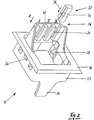
- the plug connector system S shown in FIG. 1 essentially comprises a coding frame 10 for a socket, which is part of the plug and socket fastening 11 (FIG. 2), a plug housing 12 and a socket insert 14.
- the upwardly projecting coding frame 10 is formed in one piece with a circumferential, square cover frame 16 which is chamfered in the peripheral area.
- the cover frame 16 can be a distribution plate, also called a panel, with several molded or attached coding frames 10.
- the coding frame 10 On one long side, the coding frame 10 has inwardly projecting webs 18, which form three undercut grooves 20. Two of these undercut grooves, in positions I and II, are filled with an inserted wedge 22. The grooves narrow slightly in the direction of view, whereby a clamping effect is achieved which effectively prevents the wedges 22 from falling out.
- the connector housing 12 has a comb 24 projecting into a groove 20 in position III. In positions I and II only a short stump of the combs can be seen, these are separated. If the connector housing 12 also had a comb 24 in positions I and / or II, the connector could not be inserted.
- the coding system 26 consisting of the grooves 20, the wedges 22 and the combs 24 with the positions I, II and III is designed as a unit that can be changed at any time outside the contact area of the standard connector according to the FCC, which is dealt with here. The change is made by inserting or removing wedges 22 and / or combs 24 in a position-specific manner. Details are shown in FIG. 8.
- the perspective view of the socket attachment 11 according to FIG. 2 shows the design of the coding system 26 (without the combs 24 of the connector housing 12 according to FIG. 1) more clearly.
- the wedge 22 is adapted to the shape of the undercut grooves 20. It can be inserted in the direction of arrow 28, which is also the direction of insertion R, and removed in the opposite direction. To facilitate the Two cutouts 30 are provided along the center.
- a collar 32 is formed with a guide tab 34 for the socket (not shown).
- This collar 32 also has two outer locking lugs 36 for the frame fastening and four inner locking lugs 38 for the socket insert 14 (FIG. 1).
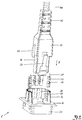
- Fig. 3 shows a connector system S in a perspective view with a connector attachment 11 and a plug 40 inserted in the plug-in direction R.
- An electrical cable 44 is guided via a flexible cable connection 42 into the plug housing 12, from which a replaceable standard plug 46 protrudes, which the electrical Contacts 48, sockets or pins, in the case shown so-called sliding contacts, holds.
- the plug 40 according to FIG. 3 can only be inserted in a socket insert 14 (not shown) (FIG. 1) if all the grooves 20 of the coding frame 10 are free, that is to say all the wedges 22 are removed. If a wedge 22 is inserted into one or more grooves 20, the corresponding comb 24 must be removed from the connector housing 12, otherwise the connector 40 cannot be inserted.
- a locking bracket 50 is shown, which secures the plug 40 inserted.
- the combs 24 are formed in one piece with the plug housing 12, but they can also be glued on, welded on or inserted into a correspondingly designed groove. This also applies to the attachment with the webs 18 according to FIG. 2.
- the connector attachment 10 and the connector housing 12 can be made of any material that is injection molded or cast and that can be machined. However, dimensionally stable plastics are preferred because of their insulation properties.
- FIG. 5 shows a combination diagram with a groove N and a comb K.
- N 1.1 the groove is empty, at N 1.2 a wedge is inserted, which is shown with a diagonal line.
- the K 1.1 comb fits into the assigned empty groove.
- the ridge of the K 1.2 is removed, which is shown with an X.
- K 1.2 also corresponds to an uncoded connector.
- N 1.1 and K 1.1 as well as N 1.2 and K 1.2 always match in pairs.
- the removed comb K 1.2 can also be used for the groove N 1.1, but K 1.1 not for N 1.2.
- N 2.1 without inserted wedge is free for all comb variants K 2.1 to K 2.4, N 2.2 and N 2.3 can be used in addition to the assigned variant of K 2.4, which also corresponds to an uncoded plug.
- the combinations can also be assessed based on the combs.
- FIG. 7 shows the possible combinations of three pairs of ridges / grooves, positions I, II and III according to FIGS. 1 and 2 being shown.
- 1 corresponds to N 3.5.
- the arrangement K 3.8 can also be inserted into this groove arrangement, which arrangement corresponds to a plug without a coding system and works with every groove combination.
- the comb combinations K 3.2, K 3.5, K 3.6 and K 3.8 can be inserted into the slot combination N 3.2.
Landscapes
- Connector Housings Or Holding Contact Members (AREA)
- Details Of Connecting Devices For Male And Female Coupling (AREA)
- Paper (AREA)
- Quick-Acting Or Multi-Walled Pipe Joints (AREA)
Applications Claiming Priority (2)
| Application Number | Priority Date | Filing Date | Title |
|---|---|---|---|
| CH1770/92A CH683881A5 (de) | 1992-06-02 | 1992-06-02 | Steckverbinderaufbau. |
| CH1770/92 | 1992-06-02 |
Publications (2)
| Publication Number | Publication Date |
|---|---|
| EP0573396A1 true EP0573396A1 (fr) | 1993-12-08 |
| EP0573396B1 EP0573396B1 (fr) | 1996-03-27 |
Family
ID=4218186
Family Applications (1)
| Application Number | Title | Priority Date | Filing Date |
|---|---|---|---|
| EP93810395A Expired - Lifetime EP0573396B1 (fr) | 1992-06-02 | 1993-06-01 | Système de connecteur |
Country Status (4)
| Country | Link |
|---|---|
| EP (1) | EP0573396B1 (fr) |
| AT (1) | ATE136165T1 (fr) |
| CH (1) | CH683881A5 (fr) |
| DE (2) | DE4228490C2 (fr) |
Cited By (6)
| Publication number | Priority date | Publication date | Assignee | Title |
|---|---|---|---|---|
| EP0776069A1 (fr) | 1995-11-24 | 1997-05-28 | Fridolin Alois Frech | Connecteur électrique multipolaire |
| EP0994533A1 (fr) * | 1998-10-13 | 2000-04-19 | Minnesota Mining And Manufacturing Company | Système de connecteur avec mécanisme de codage |
| SG98011A1 (en) * | 2000-01-07 | 2003-08-20 | Framatome Connectors Int | Cable connector for a shielded cable |
| EP1538713A1 (fr) * | 2003-12-02 | 2005-06-08 | Schaltbau GmbH | Dispositif de connexion avec saillie d'arrêt et encoche |
| EP2953213A1 (fr) * | 2014-06-05 | 2015-12-09 | Wago Verwaltungsgesellschaft mbH | Système de connecteur à fiches et élément de codage associé et procédé de codage d'un système de connecteur à fiches |
| WO2023038960A1 (fr) * | 2021-09-07 | 2023-03-16 | Raytheon Company | Dispositif de clavetage de connecteurs, système de connecteurs, et procédé pour les utiliser |
Families Citing this family (2)
| Publication number | Priority date | Publication date | Assignee | Title |
|---|---|---|---|---|
| DE4420358B4 (de) * | 1993-12-03 | 2008-07-10 | Wilhelm Rutenbeck Gmbh & Co. | Elektrisches Installationsgerät |
| CN102468578B (zh) * | 2010-11-16 | 2016-03-16 | 泰科电子(上海)有限公司 | 电连接器的壳体的防误插接装置的设计方法 |
Citations (2)
| Publication number | Priority date | Publication date | Assignee | Title |
|---|---|---|---|---|
| CH549880A (de) * | 1971-12-28 | 1974-05-31 | Siemens Ag | Mehrpolige elektrische steckverbindungsvorrichtung. |
| DE8325310U1 (de) * | 1983-09-02 | 1985-02-14 | FCT Electronic GmbH, 8000 München | Codiervorrichtung für Mehrfach-Steckverbindungen |
Family Cites Families (7)
| Publication number | Priority date | Publication date | Assignee | Title |
|---|---|---|---|---|
| DE2455409C3 (de) * | 1974-11-22 | 1981-11-19 | Siemens AG, 1000 Berlin und 8000 München | Codiervorrichtung für Mehrfach-Steckvorrichtungen |
| DE2546322B2 (de) * | 1975-10-16 | 1980-04-03 | Te Ka De Felten & Guilleaume Fernmeldeanlagen Gmbh, 8500 Nuernberg | Codiereinrichtung für Einschöbe und Einschubplätze |
| GB1568189A (en) * | 1978-02-22 | 1980-05-29 | Cannon Electric Great Britain | Electrical connectors |
| DE3331792A1 (de) * | 1983-09-02 | 1985-03-21 | FCT Electronic GmbH, 8000 München | Codiervorrichtung fuer mehrfach-steckverbindungen |
| DE3417855A1 (de) * | 1984-05-14 | 1985-11-14 | Siemens AG, 1000 Berlin und 8000 München | Steckverbinder |
| DE3601115A1 (de) * | 1986-01-16 | 1987-07-23 | Fraunhofer Ges Forschung | Unverwechselbare steckverbindung |
| DE3631115A1 (de) * | 1986-09-12 | 1988-03-24 | Licentia Gmbh | Elektrische steckverbindung fuer leiterplatten |
-
1992
- 1992-06-02 CH CH1770/92A patent/CH683881A5/de not_active IP Right Cessation
- 1992-08-27 DE DE4228490A patent/DE4228490C2/de not_active Expired - Fee Related
-
1993
- 1993-06-01 EP EP93810395A patent/EP0573396B1/fr not_active Expired - Lifetime
- 1993-06-01 DE DE59302017T patent/DE59302017D1/de not_active Expired - Lifetime
- 1993-06-01 AT AT93810395T patent/ATE136165T1/de not_active IP Right Cessation
Patent Citations (2)
| Publication number | Priority date | Publication date | Assignee | Title |
|---|---|---|---|---|
| CH549880A (de) * | 1971-12-28 | 1974-05-31 | Siemens Ag | Mehrpolige elektrische steckverbindungsvorrichtung. |
| DE8325310U1 (de) * | 1983-09-02 | 1985-02-14 | FCT Electronic GmbH, 8000 München | Codiervorrichtung für Mehrfach-Steckverbindungen |
Cited By (8)
| Publication number | Priority date | Publication date | Assignee | Title |
|---|---|---|---|---|
| EP0776069A1 (fr) | 1995-11-24 | 1997-05-28 | Fridolin Alois Frech | Connecteur électrique multipolaire |
| CH690701A5 (de) * | 1995-11-24 | 2000-12-15 | Fridolin Alois Frech | Mehrpoliger elektrischer Stecker. |
| EP0994533A1 (fr) * | 1998-10-13 | 2000-04-19 | Minnesota Mining And Manufacturing Company | Système de connecteur avec mécanisme de codage |
| SG98011A1 (en) * | 2000-01-07 | 2003-08-20 | Framatome Connectors Int | Cable connector for a shielded cable |
| EP1538713A1 (fr) * | 2003-12-02 | 2005-06-08 | Schaltbau GmbH | Dispositif de connexion avec saillie d'arrêt et encoche |
| EP2953213A1 (fr) * | 2014-06-05 | 2015-12-09 | Wago Verwaltungsgesellschaft mbH | Système de connecteur à fiches et élément de codage associé et procédé de codage d'un système de connecteur à fiches |
| WO2023038960A1 (fr) * | 2021-09-07 | 2023-03-16 | Raytheon Company | Dispositif de clavetage de connecteurs, système de connecteurs, et procédé pour les utiliser |
| JP2024531596A (ja) * | 2021-09-07 | 2024-08-29 | レイセオン カンパニー | コネクタキーイング装置、コネクタシステム、及びこれらの使用方法 |
Also Published As
| Publication number | Publication date |
|---|---|
| DE4228490C2 (de) | 1995-03-16 |
| DE4228490A1 (de) | 1993-12-09 |
| CH683881A5 (de) | 1994-05-31 |
| DE59302017D1 (de) | 1996-05-02 |
| EP0573396B1 (fr) | 1996-03-27 |
| ATE136165T1 (de) | 1996-04-15 |
Similar Documents
| Publication | Publication Date | Title |
|---|---|---|
| EP0037013B1 (fr) | Connecteur multiple | |
| DE69206266T2 (de) | Geschlechtloser elektrischer verbinder. | |
| DE69008139T2 (de) | Bauelementensatz zum gleizeitigen elektrischen Verbinden einer Mehrzahl von modularen Selbstschaltern. | |
| DE69307224T2 (de) | Steckdose von Typ "Modular Jack" mit integrierten Anschlüssen | |
| EP0265698A2 (fr) | Dispositif de connexion pour la connexion électrique des branchements d'appareils électriques | |
| DE69518846T2 (de) | Modularer verbinder mit loesbarem drahthalter | |
| EP0573396B1 (fr) | Système de connecteur | |
| DE2807017C3 (de) | Mehrpolige kodierbare Steckverbindung | |
| DE69203171T2 (de) | Verbinder. | |
| EP0706235A2 (fr) | Cosse femelle verrouillable pour une connexion électrique | |
| DE2550853B2 (de) | Elektrischer Doppelstecker | |
| DE1590632A1 (de) | Rastbare elektrische Steckkontaktverbindung | |
| DE1615655A1 (de) | Elektrisches Steckergehaeuse | |
| EP0776069B1 (fr) | Connecteur électrique multipolaire | |
| DE9218654U1 (de) | Steckverbindersystem | |
| EP1220372A2 (fr) | Boítier de connecteur avec dispositif de codage | |
| DE19614453C2 (de) | Steckbuchseneinsatz beziehungsweise Steckdose | |
| DE8701689U1 (de) | Steckereinheit | |
| DE19739503A1 (de) | Elektrischer Steckverbinder | |
| DE3617113C2 (fr) | ||
| DE9004382U1 (de) | Steckverbindersatz | |
| DE3625927C2 (de) | Rahmen zur Aufnahme und Halterung von Schaltelementen | |
| DE8108365U1 (de) | Elektrische Kupplungsvorrichtung | |
| DE9309321U1 (de) | Codierte RJ-Steckverbindung | |
| DE19631292C1 (de) | Verbesserter Western-Stecker |
Legal Events
| Date | Code | Title | Description |
|---|---|---|---|
| PUAI | Public reference made under article 153(3) epc to a published international application that has entered the european phase |
Free format text: ORIGINAL CODE: 0009012 |
|
| AK | Designated contracting states |
Kind code of ref document: A1 Designated state(s): AT BE CH DE DK ES FR GB IT LI LU NL SE |
|
| 17P | Request for examination filed |
Effective date: 19940420 |
|
| 17Q | First examination report despatched |
Effective date: 19950426 |
|
| GRAH | Despatch of communication of intention to grant a patent |
Free format text: ORIGINAL CODE: EPIDOS IGRA |
|
| GRAA | (expected) grant |
Free format text: ORIGINAL CODE: 0009210 |
|
| AK | Designated contracting states |
Kind code of ref document: B1 Designated state(s): AT BE CH DE DK ES FR GB IT LI LU NL SE |
|
| PG25 | Lapsed in a contracting state [announced via postgrant information from national office to epo] |
Ref country code: IT Free format text: LAPSE BECAUSE OF FAILURE TO SUBMIT A TRANSLATION OF THE DESCRIPTION OR TO PAY THE FEE WITHIN THE PRE;WARNING: LAPSES OF ITALIAN PATENTS WITH EFFECTIVE DATE BEFORE 2007 MAY HAVE OCCURRED AT ANY TIME BEFORE 2007. THE CORRECT EFFECTIVE DATE MAY BE DIFFERENT FROM THE ONE RECORDED.SCRIBED TIME-LIMIT Effective date: 19960327 Ref country code: ES Free format text: THE PATENT HAS BEEN ANNULLED BY A DECISION OF A NATIONAL AUTHORITY Effective date: 19960327 Ref country code: DK Effective date: 19960327 |
|
| REF | Corresponds to: |
Ref document number: 136165 Country of ref document: AT Date of ref document: 19960415 Kind code of ref document: T |
|
| REG | Reference to a national code |
Ref country code: CH Ref legal event code: NV Representative=s name: PATENTANWAELTE BREITER + WIEDMER AG |
|
| GBT | Gb: translation of ep patent filed (gb section 77(6)(a)/1977) |
Effective date: 19960328 |
|
| REF | Corresponds to: |
Ref document number: 59302017 Country of ref document: DE Date of ref document: 19960502 |
|
| ET | Fr: translation filed | ||
| PLBI | Opposition filed |
Free format text: ORIGINAL CODE: 0009260 |
|
| PLBF | Reply of patent proprietor to notice(s) of opposition |
Free format text: ORIGINAL CODE: EPIDOS OBSO |
|
| 26 | Opposition filed |
Opponent name: SIEMENS AG Effective date: 19961220 |
|
| NLR1 | Nl: opposition has been filed with the epo |
Opponent name: SIEMENS AG |
|
| PLBF | Reply of patent proprietor to notice(s) of opposition |
Free format text: ORIGINAL CODE: EPIDOS OBSO |
|
| PLBO | Opposition rejected |
Free format text: ORIGINAL CODE: EPIDOS REJO |
|
| PLBN | Opposition rejected |
Free format text: ORIGINAL CODE: 0009273 |
|
| STAA | Information on the status of an ep patent application or granted ep patent |
Free format text: STATUS: OPPOSITION REJECTED |
|
| 27O | Opposition rejected |
Effective date: 19980320 |
|
| NLR2 | Nl: decision of opposition | ||
| PGFP | Annual fee paid to national office [announced via postgrant information from national office to epo] |
Ref country code: NL Payment date: 20010621 Year of fee payment: 9 |
|
| PGFP | Annual fee paid to national office [announced via postgrant information from national office to epo] |
Ref country code: LU Payment date: 20010703 Year of fee payment: 9 |
|
| PGFP | Annual fee paid to national office [announced via postgrant information from national office to epo] |
Ref country code: BE Payment date: 20010713 Year of fee payment: 9 |
|
| REG | Reference to a national code |
Ref country code: GB Ref legal event code: IF02 |
|
| PGFP | Annual fee paid to national office [announced via postgrant information from national office to epo] |
Ref country code: SE Payment date: 20020531 Year of fee payment: 10 |
|
| PG25 | Lapsed in a contracting state [announced via postgrant information from national office to epo] |
Ref country code: LU Free format text: LAPSE BECAUSE OF NON-PAYMENT OF DUE FEES Effective date: 20020601 |
|
| PG25 | Lapsed in a contracting state [announced via postgrant information from national office to epo] |
Ref country code: BE Free format text: LAPSE BECAUSE OF NON-PAYMENT OF DUE FEES Effective date: 20020630 |
|
| BERE | Be: lapsed |
Owner name: *FRECH FRIDOLIN ALOIS Effective date: 20020630 |
|
| PG25 | Lapsed in a contracting state [announced via postgrant information from national office to epo] |
Ref country code: NL Free format text: LAPSE BECAUSE OF NON-PAYMENT OF DUE FEES Effective date: 20030101 |
|
| NLV4 | Nl: lapsed or anulled due to non-payment of the annual fee |
Effective date: 20030101 |
|
| PG25 | Lapsed in a contracting state [announced via postgrant information from national office to epo] |
Ref country code: SE Free format text: LAPSE BECAUSE OF NON-PAYMENT OF DUE FEES Effective date: 20030602 |
|
| EUG | Se: european patent has lapsed | ||
| PGFP | Annual fee paid to national office [announced via postgrant information from national office to epo] |
Ref country code: GB Payment date: 20050525 Year of fee payment: 13 |
|
| PG25 | Lapsed in a contracting state [announced via postgrant information from national office to epo] |
Ref country code: GB Free format text: LAPSE BECAUSE OF NON-PAYMENT OF DUE FEES Effective date: 20060601 |
|
| PGFP | Annual fee paid to national office [announced via postgrant information from national office to epo] |
Ref country code: FR Payment date: 20060619 Year of fee payment: 14 |
|
| GBPC | Gb: european patent ceased through non-payment of renewal fee |
Effective date: 20060601 |
|
| REG | Reference to a national code |
Ref country code: CH Ref legal event code: PFA Owner name: FRECH, FRIDOLIN ALOIS Free format text: FRECH, FRIDOLIN ALOIS#IM RAIN 7#CH-8488 TURBENTHAL (CH) -TRANSFER TO- FRECH, FRIDOLIN ALOIS#IM RAIN 7#CH-8488 TURBENTHAL (CH) |
|
| PGFP | Annual fee paid to national office [announced via postgrant information from national office to epo] |
Ref country code: AT Payment date: 20070618 Year of fee payment: 15 |
|
| PGFP | Annual fee paid to national office [announced via postgrant information from national office to epo] |
Ref country code: DE Payment date: 20070622 Year of fee payment: 15 |
|
| REG | Reference to a national code |
Ref country code: FR Ref legal event code: ST Effective date: 20080229 |
|
| PLAB | Opposition data, opponent's data or that of the opponent's representative modified |
Free format text: ORIGINAL CODE: 0009299OPPO |
|
| PGFP | Annual fee paid to national office [announced via postgrant information from national office to epo] |
Ref country code: CH Payment date: 20080620 Year of fee payment: 16 |
|
| PG25 | Lapsed in a contracting state [announced via postgrant information from national office to epo] |
Ref country code: FR Free format text: LAPSE BECAUSE OF NON-PAYMENT OF DUE FEES Effective date: 20070702 |
|
| PG25 | Lapsed in a contracting state [announced via postgrant information from national office to epo] |
Ref country code: DE Free format text: LAPSE BECAUSE OF THE APPLICANT RENOUNCES Effective date: 20080715 |
|
| PG25 | Lapsed in a contracting state [announced via postgrant information from national office to epo] |
Ref country code: AT Free format text: LAPSE BECAUSE OF NON-PAYMENT OF DUE FEES Effective date: 20080601 |
|
| REG | Reference to a national code |
Ref country code: CH Ref legal event code: PL |
|
| PG25 | Lapsed in a contracting state [announced via postgrant information from national office to epo] |
Ref country code: LI Free format text: LAPSE BECAUSE OF NON-PAYMENT OF DUE FEES Effective date: 20090630 Ref country code: CH Free format text: LAPSE BECAUSE OF NON-PAYMENT OF DUE FEES Effective date: 20090630 |