EP0575183B1 - Zusammenlegbarer Palettenbehälter - Google Patents
Zusammenlegbarer Palettenbehälter Download PDFInfo
- Publication number
- EP0575183B1 EP0575183B1 EP93304752A EP93304752A EP0575183B1 EP 0575183 B1 EP0575183 B1 EP 0575183B1 EP 93304752 A EP93304752 A EP 93304752A EP 93304752 A EP93304752 A EP 93304752A EP 0575183 B1 EP0575183 B1 EP 0575183B1
- Authority
- EP
- European Patent Office
- Prior art keywords
- flap
- container
- panel
- pallet
- transition
- Prior art date
- Legal status (The legal status is an assumption and is not a legal conclusion. Google has not performed a legal analysis and makes no representation as to the accuracy of the status listed.)
- Expired - Lifetime
Links
Images

Classifications
-
- B—PERFORMING OPERATIONS; TRANSPORTING
- B65—CONVEYING; PACKING; STORING; HANDLING THIN OR FILAMENTARY MATERIAL
- B65D—CONTAINERS FOR STORAGE OR TRANSPORT OF ARTICLES OR MATERIALS, e.g. BAGS, BARRELS, BOTTLES, BOXES, CANS, CARTONS, CRATES, DRUMS, JARS, TANKS, HOPPERS, FORWARDING CONTAINERS; ACCESSORIES, CLOSURES, OR FITTINGS THEREFOR; PACKAGING ELEMENTS; PACKAGES
- B65D19/00—Pallets or like platforms, with or without side walls, for supporting loads to be lifted or lowered
- B65D19/02—Rigid pallets with side walls, e.g. box pallets
- B65D19/06—Rigid pallets with side walls, e.g. box pallets with bodies formed by uniting or interconnecting two or more components
- B65D19/20—Rigid pallets with side walls, e.g. box pallets with bodies formed by uniting or interconnecting two or more components made wholly or mainly of paper
-
- B—PERFORMING OPERATIONS; TRANSPORTING
- B65—CONVEYING; PACKING; STORING; HANDLING THIN OR FILAMENTARY MATERIAL
- B65D—CONTAINERS FOR STORAGE OR TRANSPORT OF ARTICLES OR MATERIALS, e.g. BAGS, BARRELS, BOTTLES, BOXES, CANS, CARTONS, CRATES, DRUMS, JARS, TANKS, HOPPERS, FORWARDING CONTAINERS; ACCESSORIES, CLOSURES, OR FITTINGS THEREFOR; PACKAGING ELEMENTS; PACKAGES
- B65D19/00—Pallets or like platforms, with or without side walls, for supporting loads to be lifted or lowered
-
- B—PERFORMING OPERATIONS; TRANSPORTING
- B65—CONVEYING; PACKING; STORING; HANDLING THIN OR FILAMENTARY MATERIAL
- B65D—CONTAINERS FOR STORAGE OR TRANSPORT OF ARTICLES OR MATERIALS, e.g. BAGS, BARRELS, BOTTLES, BOXES, CANS, CARTONS, CRATES, DRUMS, JARS, TANKS, HOPPERS, FORWARDING CONTAINERS; ACCESSORIES, CLOSURES, OR FITTINGS THEREFOR; PACKAGING ELEMENTS; PACKAGES
- B65D2519/00—Pallets or like platforms, with or without side walls, for supporting loads to be lifted or lowered
- B65D2519/00004—Details relating to pallets
- B65D2519/00009—Materials
- B65D2519/00014—Materials for the load supporting surface
- B65D2519/00019—Paper
-
- B—PERFORMING OPERATIONS; TRANSPORTING
- B65—CONVEYING; PACKING; STORING; HANDLING THIN OR FILAMENTARY MATERIAL
- B65D—CONTAINERS FOR STORAGE OR TRANSPORT OF ARTICLES OR MATERIALS, e.g. BAGS, BARRELS, BOTTLES, BOXES, CANS, CARTONS, CRATES, DRUMS, JARS, TANKS, HOPPERS, FORWARDING CONTAINERS; ACCESSORIES, CLOSURES, OR FITTINGS THEREFOR; PACKAGING ELEMENTS; PACKAGES
- B65D2519/00—Pallets or like platforms, with or without side walls, for supporting loads to be lifted or lowered
- B65D2519/00004—Details relating to pallets
- B65D2519/00009—Materials
- B65D2519/00049—Materials for the base surface
- B65D2519/00054—Paper
-
- B—PERFORMING OPERATIONS; TRANSPORTING
- B65—CONVEYING; PACKING; STORING; HANDLING THIN OR FILAMENTARY MATERIAL
- B65D—CONTAINERS FOR STORAGE OR TRANSPORT OF ARTICLES OR MATERIALS, e.g. BAGS, BARRELS, BOTTLES, BOXES, CANS, CARTONS, CRATES, DRUMS, JARS, TANKS, HOPPERS, FORWARDING CONTAINERS; ACCESSORIES, CLOSURES, OR FITTINGS THEREFOR; PACKAGING ELEMENTS; PACKAGES
- B65D2519/00—Pallets or like platforms, with or without side walls, for supporting loads to be lifted or lowered
- B65D2519/00004—Details relating to pallets
- B65D2519/00009—Materials
- B65D2519/00084—Materials for the non-integral separating spacer
- B65D2519/00089—Paper
-
- B—PERFORMING OPERATIONS; TRANSPORTING
- B65—CONVEYING; PACKING; STORING; HANDLING THIN OR FILAMENTARY MATERIAL
- B65D—CONTAINERS FOR STORAGE OR TRANSPORT OF ARTICLES OR MATERIALS, e.g. BAGS, BARRELS, BOTTLES, BOXES, CANS, CARTONS, CRATES, DRUMS, JARS, TANKS, HOPPERS, FORWARDING CONTAINERS; ACCESSORIES, CLOSURES, OR FITTINGS THEREFOR; PACKAGING ELEMENTS; PACKAGES
- B65D2519/00—Pallets or like platforms, with or without side walls, for supporting loads to be lifted or lowered
- B65D2519/00004—Details relating to pallets
- B65D2519/00009—Materials
- B65D2519/00154—Materials for the side walls
- B65D2519/00159—Paper
-
- B—PERFORMING OPERATIONS; TRANSPORTING
- B65—CONVEYING; PACKING; STORING; HANDLING THIN OR FILAMENTARY MATERIAL
- B65D—CONTAINERS FOR STORAGE OR TRANSPORT OF ARTICLES OR MATERIALS, e.g. BAGS, BARRELS, BOTTLES, BOXES, CANS, CARTONS, CRATES, DRUMS, JARS, TANKS, HOPPERS, FORWARDING CONTAINERS; ACCESSORIES, CLOSURES, OR FITTINGS THEREFOR; PACKAGING ELEMENTS; PACKAGES
- B65D2519/00—Pallets or like platforms, with or without side walls, for supporting loads to be lifted or lowered
- B65D2519/00004—Details relating to pallets
- B65D2519/00258—Overall construction
- B65D2519/00263—Overall construction of the pallet
- B65D2519/00273—Overall construction of the pallet made of more than one piece
-
- B—PERFORMING OPERATIONS; TRANSPORTING
- B65—CONVEYING; PACKING; STORING; HANDLING THIN OR FILAMENTARY MATERIAL
- B65D—CONTAINERS FOR STORAGE OR TRANSPORT OF ARTICLES OR MATERIALS, e.g. BAGS, BARRELS, BOTTLES, BOXES, CANS, CARTONS, CRATES, DRUMS, JARS, TANKS, HOPPERS, FORWARDING CONTAINERS; ACCESSORIES, CLOSURES, OR FITTINGS THEREFOR; PACKAGING ELEMENTS; PACKAGES
- B65D2519/00—Pallets or like platforms, with or without side walls, for supporting loads to be lifted or lowered
- B65D2519/00004—Details relating to pallets
- B65D2519/00258—Overall construction
- B65D2519/00313—Overall construction of the base surface
- B65D2519/00328—Overall construction of the base surface shape of the contact surface of the base
- B65D2519/00343—Overall construction of the base surface shape of the contact surface of the base contact surface being substantially in the form of a panel
-
- B—PERFORMING OPERATIONS; TRANSPORTING
- B65—CONVEYING; PACKING; STORING; HANDLING THIN OR FILAMENTARY MATERIAL
- B65D—CONTAINERS FOR STORAGE OR TRANSPORT OF ARTICLES OR MATERIALS, e.g. BAGS, BARRELS, BOTTLES, BOXES, CANS, CARTONS, CRATES, DRUMS, JARS, TANKS, HOPPERS, FORWARDING CONTAINERS; ACCESSORIES, CLOSURES, OR FITTINGS THEREFOR; PACKAGING ELEMENTS; PACKAGES
- B65D2519/00—Pallets or like platforms, with or without side walls, for supporting loads to be lifted or lowered
- B65D2519/00004—Details relating to pallets
- B65D2519/00258—Overall construction
- B65D2519/00492—Overall construction of the side walls
- B65D2519/00497—Overall construction of the side walls whereby at least one side wall is made of one piece
-
- B—PERFORMING OPERATIONS; TRANSPORTING
- B65—CONVEYING; PACKING; STORING; HANDLING THIN OR FILAMENTARY MATERIAL
- B65D—CONTAINERS FOR STORAGE OR TRANSPORT OF ARTICLES OR MATERIALS, e.g. BAGS, BARRELS, BOTTLES, BOXES, CANS, CARTONS, CRATES, DRUMS, JARS, TANKS, HOPPERS, FORWARDING CONTAINERS; ACCESSORIES, CLOSURES, OR FITTINGS THEREFOR; PACKAGING ELEMENTS; PACKAGES
- B65D2519/00—Pallets or like platforms, with or without side walls, for supporting loads to be lifted or lowered
- B65D2519/00004—Details relating to pallets
- B65D2519/00547—Connections
- B65D2519/00577—Connections structures connecting side walls, including corner posts, to each other
- B65D2519/00582—Connections structures connecting side walls, including corner posts, to each other structures intended to be disassembled, i.e. collapsible or dismountable
- B65D2519/00587—Connections structures connecting side walls, including corner posts, to each other structures intended to be disassembled, i.e. collapsible or dismountable side walls directly connected to each other
- B65D2519/00592—Connections structures connecting side walls, including corner posts, to each other structures intended to be disassembled, i.e. collapsible or dismountable side walls directly connected to each other by means of hinges
- B65D2519/00597—Connections structures connecting side walls, including corner posts, to each other structures intended to be disassembled, i.e. collapsible or dismountable side walls directly connected to each other by means of hinges integrally formed
-
- B—PERFORMING OPERATIONS; TRANSPORTING
- B65—CONVEYING; PACKING; STORING; HANDLING THIN OR FILAMENTARY MATERIAL
- B65D—CONTAINERS FOR STORAGE OR TRANSPORT OF ARTICLES OR MATERIALS, e.g. BAGS, BARRELS, BOTTLES, BOXES, CANS, CARTONS, CRATES, DRUMS, JARS, TANKS, HOPPERS, FORWARDING CONTAINERS; ACCESSORIES, CLOSURES, OR FITTINGS THEREFOR; PACKAGING ELEMENTS; PACKAGES
- B65D2519/00—Pallets or like platforms, with or without side walls, for supporting loads to be lifted or lowered
- B65D2519/00004—Details relating to pallets
- B65D2519/00547—Connections
- B65D2519/00636—Connections structures connecting side walls to the pallet
- B65D2519/00641—Structures intended to be disassembled
- B65D2519/00646—Structures intended to be disassembled by means of hinges
- B65D2519/00651—Structures intended to be disassembled by means of hinges integrally formed
-
- B—PERFORMING OPERATIONS; TRANSPORTING
- B65—CONVEYING; PACKING; STORING; HANDLING THIN OR FILAMENTARY MATERIAL
- B65D—CONTAINERS FOR STORAGE OR TRANSPORT OF ARTICLES OR MATERIALS, e.g. BAGS, BARRELS, BOTTLES, BOXES, CANS, CARTONS, CRATES, DRUMS, JARS, TANKS, HOPPERS, FORWARDING CONTAINERS; ACCESSORIES, CLOSURES, OR FITTINGS THEREFOR; PACKAGING ELEMENTS; PACKAGES
- B65D2519/00—Pallets or like platforms, with or without side walls, for supporting loads to be lifted or lowered
- B65D2519/00004—Details relating to pallets
- B65D2519/00736—Details
- B65D2519/00865—Collapsible, i.e. at least two constitutive elements remaining hingedly connected
- B65D2519/00875—Collapsible, i.e. at least two constitutive elements remaining hingedly connected collapsible side walls
- B65D2519/0091—Collapsible, i.e. at least two constitutive elements remaining hingedly connected collapsible side walls whereby all side walls are hingedly connected to each other
- B65D2519/00915—Collapsible, i.e. at least two constitutive elements remaining hingedly connected collapsible side walls whereby all side walls are hingedly connected to each other and one or more side walls being foldable along a median line
Definitions
- the present invention relates in general to a container apparatus and in particular to a collapsible container apparatus attached to a pallet so as to substantially facilitate the collapse of the container to a minimized profile when storage of the apparatus is required while alternatively providing a self-prompting sealed container area to prevent the migration of materials from within the apparatus to the outside environment when the apparatus is fully deployed.
- Pallets have been used for many years by shippers and transporters of various materials. These pallets typically provide a flat and sturdy surface on which materials can be placed and stacked. In order to assure that the materials remain on the pallet, various sized and shaped containers have been attached to the tops of pallets so as to present a bounded area in which to place and/or remove the materials being shipped or stored.
- Containers that have been conventionally attached to pallets range from nothing more than four walls and a bottom which utilize the pallet top surface as a support, to more intricate collapsible pallet-container combinations. Most early pallet-container combinations were not collapsible and retained their shape, configuration and dimensions whether in use or not, thereby requiring excess space when stored between uses.
- the prior art pallet-container combinations include U.S. Pat. No. 4,373,637 to Shippell which discloses a pallet-container combination wherein the container portion requires substantial effort to deploy and collapse.
- To configure the container portion into the deployed position for example, bottom flaps 56 and 58 must in Shippell be manually repositioned from their non-deployed position. Similarly, upon reconfiguration of the container from the deployed position to the collapsed position, the bottom flaps 56 and 58 must again be manually repositioned.
- Additional prior art pallet-container combinations include U.S. Pat. No. 5,071,010 to Carufel/Zeman ; U.S. Pat. No. 4,969,559 to Nederveld ; U.S. Pat. No. 4,949,898 to Nederveld ; U.S. Pat. No. 4,793,507 to Delplanque ; U.S. Pat. No. 4,880,141 to Gossler , et al.; U.S. Pat. No. 4,712,687 to Silcott , et al.; U.S. Pat. No. 4,606,461 to Bolton Sr. ; and U.S. Pat. No. 4,545,482 to Novatny . While this prior art relates in varying degrees to the present invention, they lack the many advantages of the present invention.
- An additional object of the invention is to provide a container portion that has an automatically sealed lower periphery to prevent inadvertent or accidental migration of the contents within the container to the outside environment.
- the present invention comprises a collapsible pallet container apparatus for automatically prompting the collapse and deployment of the apparatus so that upon full articulated deployment articles may be positioned within the interior region of the container while on full collapse the overall profile of the apparatus is minimized.
- the apparatus comprises a pallet and a container attached to the top surface of the pallet.
- the container comprises front panel members, back panel members and one or more side panel members that are positioned between the front and back panel members.
- the front, back, and one or more side panels members each respectively have an upper and lower edge, as well as respective side edges, which are attached to one another so as to form a contiguous periphery of the container.
- At least one of the one or more side panels contains an articulation means to allow the side panel, and in turn the container, to fold inwardly towards the interior region of the container upon reconfiguration of the apparatus from an articulated deployed position to a fully collapsed position.
- the container further comprises a bottom panel which includes a front, back and one or more side edges and which covers and is restrainably attached to at least a portion of the top surface of the pallet.
- the bottom panel attaches the container to the pallet by not only being attached to a portion of the pallet but by also being hingedly emanating from at least one of the front, back and side panels at the respective front, back and side edges of the bottom panel.
- collapse prompting members are associated with at least one of the bottom and one or more side panel articulation members so as to provide for a biasing of the apparatus from the deployed position to the collapsed position upon the movement or jarring of at least one of the front, back and one or more side panel members.
- the apparatus in this preferred embodiment also includes automatically deployable and collapsible sealing flaps emanating and hingedly attached to at least one of the one or more side panel members at seal flap folds.
- Each of the sealing flaps is positionable so that upon deployment of the container the sealing flaps move from their stored location adjacent to the respective one or more side panel members to a position juxtaposed and on top of the bottom panel.
- each of the sealing flaps is capable of automatically moving positions from juxtaposed and on top of said bottom panel when in the fully deployed position to their respective storage location adjacent to a side panel member.
- the sealing flaps permit the apparatus to collapse to an overall profile that is now minimized.
- seal flap folds which attach the sealing flaps to the one or more side panel members, prevent the migration of articles from within the interior region of the container to the outside environment.
- wing flaps emanating from a portion of the lower edges of the one or more side panel members.
- the wing flaps are capable of automatic deployment from a position adjacent to the respective one or more side panel members, when in the stored position, to a position juxtaposed and on top of a portion of the bottom panel when the container is articulated to full deployment.
- Each of the wing flaps is restrainably attached to a portion of the bottom panel as well as hingedly attached to at least a portion of the lower edge of respective one or more side panel members.
- the hinge between the wing flaps and respective one or more side panel members is utilized to further prevent migration of articles from the interior region of the container to the outside environment.
- the lower periphery of the container as defined by the lower edges of the back panel member, the front panel member, the bottom panel and the one or more side panel members is completely sealed and enclosed to prevent and preclude migration of articles between the top surface of the pallet and the respective lower edges of the front panel, back panel and one or more side panel members.
- the apparatus further comprises a single front panel, a single back panel, positioned across from the front panel and two side panels located opposite each other and between the front and back panels.
- Each of the side panels contains a panel articulation fold that traverses the side panels from their respective lower edges to their respective upper edges and which bisects the side panels so that the distance between respective side edges and the articulation fold is approximately equal to each other, thereby dividing the respective side panels in half.
- the articulation folds move inwardly towards each other and the interior region of the container thereby drawing the front and back panels inwardly towards each other -- to reduce the distance between the two panels and, in turn, reduce the overall collapsed profile of the container and apparatus.
- the sealing flaps comprise two sealing flaps, one of each being positioned on each of the respective opposite side panels and transversing a distance from the lower edge of the back panel towards the front panel to a location beyond the articulation fold within the respective side panel.
- Each of the respective sealing flaps further contains a starburst score pattern proximate to the articulation folds in the respective side panels so that upon collapse of the container the sealing flaps are adjacent to and wrapped around the respective articulation folds and in turn the respective side panels.
- the wing flap which, in this embodiment, includes a recessed area to be utilized for receipt of a portion of the adjacent sealing flap. Upon full deployment, the respective adjacent sealing flap and wing flap become substantially co-planar to each other so as to be juxtaposed to the bottom panel.
- the bottom panel of the preferred embodiment comprises a collapse flap, a pallet attachment flap, a transition flap member and bottom panel flap alignment members wherein the collapsed flap, pallet attachment flap and transition flap member cooperate with each other as well as with the remainder of the container so as to facilitate the transition of the apparatus from a fully articulated and deployed configuration to a fully collapsed position wherein the overall profile of the apparatus is minimized.
- the bottom panel flap alignment member further comprises a male tab positioned on the front edge of the pallet attachment flap and a female slot operably positioned in the transition flap member, so that upon deployment of the container the male tab will engage the female slot -- to effectively align, lock and stabilize the container by securing the relative position of the collapse flap, pallet attachment flap and transition flap member.
- the locking of the male tab and female slot may further be enhanced by an interference friction fit created between the male tab and female slot or alternatively, by a positive non-retractable interface upon insertion of the male tab into the female slot.
- the lower periphery of the container is configured so that the collapse flap, pallet attachment flap and transition flap members are utilized to effectively seal any gaps that may exist along a portion of the lower periphery of the container so as to prevent migration of articles from the interior region of the container to the outside environment.
- the collapse flap is position between the lower edge of the back panel and the pallet attachment flap and has a height that corresponds to the overall thickness of the container when in the fully collapsed orientation; so as to permit the container to be folded over, positioned upon and hingedly attached to the top surface of the pallet.
- the pallet attachment flap, hingedly emanating from the collapse flap at pallet attachment flap fold is secured to a portion of the top surface of the pallet.
- the pallet attachment flap fold is positioned at the back edge of the pallet attachment flap which is opposite to the front edge and spans the distance between the two respective side edges.
- the front edge of the pallet attachment flap is positioned at and between the articulation folds in the respective one or more side panels when the container is in the fully articulated deployed configuration.
- the transition flap members of this preferred embodiment further contains a front edge, a back edge and two side edges positioned between the front and back edges wherein the front edge of the transition flap members and the lower edge of the front panel members are hingedly attached by transition flap folds.
- the back edge of the transition flap members is positioned so as to extend at and between the panel articulation folds in the respective one or more side panels when the container is in the fully articulated deployed position.
- the transition flap members further comprise a transition flap center panel and two transition flap side panels hingedly attached to each opposite side edge of the transition flap center panel by transition panel folds.
- the respective wing flaps which hingedly emanate from respective side panel members are attached to the two respective transition flap side panels. Such attachment facilitates the sealing of the lower periphery of the container by preventing migration of articles through any gaps that may have existed between the transition flap side panels and the respective side panel members.
- the transition flap folds, wing flap folds and respective panel folds are hinged through a type of specific scored and crushed alternating fold.
- Such alternating scoring and crushing biases the respective wing flaps, front panel members, side panel members, transition flap center panel and transition flap side panels to a position of either 0 or 90 degree orientation to respective adjacent wing flap, front panel member, side panel members, transition flap center panel and transition flap side panel so as to create a bias in the overall container towards at least a preliminarily collapsed position.
- biasing can be utilized to prompt collapse by, for example, elevating, jarring, or otherwise simply reorientating at least one of the front, back and side panel members when the container is in its fully articulated and deployed position, while simultaneously disengaging the bottom panel flap alignment members.
- the container further comprises closure flap members which hingedly emanate from the respective side edges of at least one of the front and back panels.
- the closure flaps comprise two closure flaps, each of which-includes an upper edge, a lower edge and two side edges positioned opposite to each other and between the upper and lower edges.
- One of the closure flaps emanates from the side edge of the front panel while the second of the closure flaps emanates from a side edge of the back panel by closure flap folds.
- each closure flap is restrainably attached to the adjoining side panel so as to integrate the front, back and side panels as well as the bottom panel into a single integrated container of contiguous material.
- the single integrated contiguous container may be formed out of two blanks of container material.
- the first material blank comprises the back panel, the collapse flap, the pallet attachment flap, one of the side panels, one of the closure flaps, one of the wing flaps and one of the sealing flaps while the second material blank comprises the front panel, the transition flap means (with transition flap center and side panels), the second side panel means, the second closure flap, the second wing flap and the second sealing flap.
- these two material blanks form a contiguous integrated container as described herein.
- These blanks and the apparatus may be formed out of many different types of material. While the pallet and the container need not be constructed from the same material, it is envisioned that the container portion be constructed out of a substantially biodegradable, paperboard material, preferably corrugated paperboard. Similarly, the pallet may be formed from a corrugated paperboard material or any other materials that may be appropriate for its function.
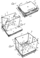
- Collapsible pallet container apparatus 10 is shown in Fig. 1 in the fully collapsed position in which the overall profile of the apparatus is minimized.
- Apparatus 10 comprises pallet means 11 and container means 12 which is attached thereto.
- Container means 12 comprises front panel means 14, back panel means 13, side panel means 17-18 and 19-20, and bottom panel means 29, 30 and 39.
- Container means 12 is restrainably attached to pallet means 11 at pallet attachment flap 29, which comprises a portion of bottom panel means 29, 30 and 39.
- Bottom panel means 29, 30 and 39 includes pallet attachment flap 29, transition flap means 30a through c and collapse flap 39, as fully shown in Figs. 3, 5, 9 and 10.
- container means 12 lies juxtapose to overlay pallet means 11 so as to minimize the area required for storage of apparatus 10.
- Container means 12 is collapsed with back panel means 13 and front panel means 14 substantially parallel to each other as well as parallel to pallet means 11.
- Side panel means 17-18 and 19-20 are positioned so as to lie between and adjacent to back and front panel means 13 and 14 and are sandwiched therebetween.
- side panel means 17-18 and 19-20 are folded in such a way so that side panel means portions 17 and 19 overlie side panel means portions 18 and 20 respectively, thereby forming a "V" about articulation folds 22 and 21.
- Pallet attachment flap 29 is operably positioned between and juxtaposed to both front panel means 14 and pallet means 11.
- collapse flap 39 is hingedly attached to lower edge 23 of back panel means 13 as well as to pallet attachment flap 29 at scored fold 24.
- Fig. 2 shows apparatus 10 in a preliminarily collapsed position, where pallet attachment flap 29 of container means 12 remains juxtaposed to and restrainably attached to pallet means 11.
- Pallet attachment flap 29 is further attached to collapse flap 39 which is substantially co-planar to pallet attachment flap 29.
- back panel means 13 Also attached to collapse flap 39 at back edge 23 is back panel means 13.
- container means 12 is only preliminarily collapsed so that front, back and side panel means 14, 13, 17-18 and 19-20, respectively, are substantially vertical as well as perpendicular to pallet means 11.
- Back panel means 13 is also hingedly attached to side panel means portion 19 which emanates from back panel means at side edge 27.
- closure flap means 15 is also hingedly emanating from back panel 13 and overlies side panel means portion 17, thereby attaching side panel means 17-18 to back panel means 13.
- Front panel means 14 is similarly situated with respect to transition flap means 30 and side panel means portions 18 and 20.
- Side panel means portion 18 is hingedly emanating from side edge 26 of front panel means 14.
- closure flap means 16 is hingedly emanating from front panel means 14 and overlies side panel means portion 20 thereby attaching front panel means 14 to side panel means 19-20.
- Articulation folds 22 and 21 are positioned within the respective side panel means 17-18 and 19-20 so as to traverse the distance between the upper and lower edges of side panel means 17-18 and 19-20, with side panel means 17-18 and 19-20 being of substantially the same size.
- articulation folds 22 and 21 depart from each other to a position substantially co-planar to that of side edges 25 and 26, and 27 and 28 respectively, so as to eliminate the "V" shaped fold region otherwise formed in side panel means 17-18 and 19-20.
- Side panel means 17-18 and 19-20 respectively are thus substantially co-planar and parallel to each other, when container means 12 is in its fully erected deployed position.
- Transition flap means 30 hingedly emanates from the lower edge 52 of front panel means 14 so as to be able to move from its collapsed position adjacent and parallel to front panel means 14, to its deployed position adjacent to pallet means 11 and substantially perpendicular to front panel means 14.
- Transition flap means 30 is further joined to side panel means portions 18 and 20 respectively by wing flap means 46 and 47 respectively attached to transition flap side panels 30c and 30a.
- Wing flap means 46 and 47 hingedly emanate from side panel means portions 18 and 20 at lower edges 38 and 37, respectively overlie and are attached to a portion of the respective top surfaces of transition flap side panels 30c and 30a, as shown in Fig. 3.
- Transition flap side panels 30c and 30a are connected to transition flap center panel 30b by transition folds 35 and 34 respectively.
- Transition folds 34 and 35 allow transition flap means 30 with flap portions 30a, b and c, to become co-planar upon deployment of container means 12, while permitting transition flap side panels 30a and 30c to turn inwardly and overlie transition flap center panel 30b so as to be juxtaposed thereto when container means 12 is in its collapsed position.
- Bottom panel flap alignment means male tab member 41 is operably positioned on the front edge 36 of pallet attachment flap means 29 for aligned engagement within female slot 31 on the back edge of transition flap means 30, upon full deployment of apparatus 10 as shown in Fig. 3.
- sealing flap means 32 and 33 hingedly emanate from respective side panel means 17-18 and 19-20 at lower edges 38 and 37. Sealing flap means 32 and 33 are positioned so as to extend from back panel means 13 towards front panel means 14, past articulation folds 22 and 21. In their collapsed position, sealing flap means 32 and 33 become automatically positioned juxtaposed to side panel means 17-18 and 19-20, respectively.
- sealing flap means 32 and 33 are automatically prompted from their storage position adjacent to side panel means 17-18 and 19-20, to positions juxtaposed to and on top of pallet attachment flap 29, so as to be substantially co-planar to wing flap means 46 and 47, and perpendicular to side panel means 17-18 and 19-20.
- FIG. 3 demonstrates apparatus 10 in its fully articulated and deployed position.
- Front panel means 14, back panel means 13, side panel means, 17-18 and 19-20 and closure flap means 15 and 16 are all substantially vertical, perpendicular to pallet means 11, and interconnected so as to form an article-containing structure corresponding to container means 12.
- Back panel means 13 is positioned opposite front panel means 14, each of which are substantially perpendicular to side panel means 17-18 and 19-20, which are fully extended and opposite to each other.
- Side edges 25 and 26 and articulation fold 22 are all substantially co-planar with each other as well as with side panel means 17-18.
- side edges 27 and 28 and articulation fold 21 are all substantially co-planar with each other as well as with side panel means 19-20.
- the lower periphery of container means 12, as bounded by the lower edges 23, 52, 38 and 37 of the back panel means 13, front panel means 14 and side panel means 17-18 and 19-20 respectively, is, in the preferred embodiment, fully congruent with the outer periphery of pallet means 11.
- Bottom panel means 29, 30 and 39 overlie pallet means 11 so as to substantially cover the entirety of the top surface of pallet means 11, as shown in Fig. 3.
- pallet attachment flap 29, collapse flap 39 and transition flap means 30 are substantially co-planar to each other and parallel to pallet means 11.
- pallet attachment flap 29 and transition flap means 30 are positioned so that the front edge 36 of pallet attachment flap 29 and the back edge 40 of transition flap means 30 are adjacent one another, with male tab member 41 of the bottom panel flap alignment means, operably engaging female slot 31 thereby assisting in restraining the relative positions of bottom panel means 29, 30 and 39 and, in turn, assisting in maintaining container means 12 from inadvertent or accidental collapse.
- the addition of articles into the container further maintains the bottom panel means 29, 30 and 39 and indeed the remainder of container means 12 in its deployed orientation.
- Wing flap means 46 and 47 are hingedly attached to side panel means portions 18 and 20 respectively, as well as are attached to transition flap side panels means 30c and 30a, so as to be substantially parallel to and completely overlie transition flap side panels 30c and 30a upon full deployment of container means 12.
- Wing flap means 46 and 47 further contain recessed areas 42 and 43 for receipt of portions of sealing flap means 32 and 33, respectively, upon full deployment and articulation of container means 12.
- wing flap means 46 and 47 and sealing flap means 32 and 33 become substantially coplanar to each other, and collectively juxtaposed to portions of transition flap means 30 and pallet attachment flap 29 respectively.
- Sealing flap means 32 and 33, and wing flaps 46 and 47 are further positioned so that upon deployment of container means 12, the lower periphery of container means 12, is completely sealed so as to prevent materials held within container means 12 from migrating between lower edges 23, 52, 37 and 38; and pallet means 11.
- pallet means 11 is attached to container means 12 at pallet attachment flap 29 which contains male tab member 41 on front edge 36.
- Collapse flap 39 which is itself not attached to pallet means 11, is hingedly attached to back panel means 13 at lower edge 23.
- Collapse flap 39 is hingedly attached at its other side to pallet attachment flap 29 at double score fold 24.
- the distance between fold line 24 and back edge 23 comprises the height of collapse flap 39 when container means 12 and apparatus 10 are in the fully collapsed position; the same height of the overall profile of container means 12 when it has been minimized upon collapse.
- wing flap means 46 and 47 and transition flap means 30 move from their respective positions adjacent and juxtaposed to side panel means portions 18 and 20 and front panel means 14, to their deployed positions.
- wing flaps 46 and 47 abut the now horizontal transition flap means 30 which has assumed a position co-planar with pallet attachment flap 29, juxtaposed to pallet means 11.
- Collapse prompting means embodied by crushed and scored hinges 34, 35 and 52, facilitate the transition of container means 12 from a deployed position to preliminary and fully collapsed positions and vice-versa.
- sealing flap means 32 and 33 move from their positions adjacent side panel means 17-18 and 19-20 to positions substantially co-planar to wing flap means 46 and 47, respectively.
- Wing flap means 46 and 47 receive sealing flap means 32 and 33 in recessed areas 42 and 43 so as to effectively seal the lower periphery of container means 12 against article migration.
- the starburst scoring pattern 44 and 45 of sealing flap means 32 and 33 imparts flexibility to sealing flap means 32 and 33 to enable automatic deployment from their respective positions adjacent side panel means 17-18 and 19-20 to rotate 90 degrees about folds 38 and 37, (Figs. 9 and 10) and adjacent articulation folds 22 and 21, respectively adjacent thereto, as well as to facilitate similar repositioning upon collapse of container means 12.
- Bottom panel means 29, 30 and 39 cover substantially the entirety of the surface area bounded by pallet means 11, with the bottom panel means at least partially maintained in position by the cooperation of male tab member 41 of the bottom panel flap alignment means, operably engaging female slot 31 of bottom panel flap alignment means.
- Collapse flap 39, sealing flap means 32 and 33, wing flap means 46 and 47 and transition flap means 30 are all hingedly attached to back panel means 13, side panel means 17-18 and 19-20 and front panel means 14, respectively, at lower edges 23 (Fig. 9), 38, 37 and 52 (Fig. 3).
- Apparatus 10 is shown in the fully collapsed position for storage in Fig. 6.
- Pallet attachment flap 29 remains attached to pallet means 11 thereby keeping container means 12 attached to pallet means 11 at all times including during non-deployment.
- Container means 12 is permitted to fold in upon itself about collapse flap 39 to reduce and minimize the overall profile of apparatus 10 when not in use.
- the total height required by apparatus 10 while in the collapsed position is the height of pallet means 11 in combination with the height of collapse flap 39.
- Collapse flap 39 is hingedly attached to both back panel means 13 and pallet attachment flap 29 at lower edge 23 and double score fold 24 respectively. This configuration allows container means 12 to fold back towards and on top of pallet means 11 again minimizing the space required for storage of apparatus 10. Sandwiched between pallet attachment flap 29 and back panel means 13 is the remainder of container means 12.
- FIG 7 shows another view of apparatus 10 in its fully collapsed position.
- Pallet means 11 is attached to container means 12 at pallet attachment flap 29, with the remainder of container means 12 folded back over flap 29, about collapse flap 39.
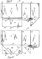
- Collapse prompting means comprising alternating scored and crushed hinge folds along lower edge 37 of side panel means 19-20, are shown enlarged in Fig. 8.
- the folds are scored in such a way so as to permit one set of scoring 55 and 56 to be recessed, or offset, relative to their mated scores 54 and 57, when container means 12 is articulated to the collapsed position.
- Interposed between scores along lower edge 37 are non-scored, crushed regions 53 and 58.
- crushed regions such as 53 and 58 should not be positioned beneath perpendicular folds such as articulation folds 21 or 22.
- hinge fold prompts adjoining flaps and panels to both a 0 degree and 90 degree orientation, to create a bias therebetween, to prompt respective side panels, wing flaps, and bottom panel means into either a fully deployed or preliminarily collapsed orientation.
- Container blank 12a is shown in Fig. 9 as including closure flap means 15 hingedly emanating from the side edge of back panel means 13 at closure flap fold 25; and collapse flap 39 hingedly emanating from back panel means 13 at lower edge 23 which is also attached to pallet attachment flap 29 at double scored fold 24. Also shown as embodied by this blank 12a portion are: pallet attachment flap 29 with male tab member 41; side panel means 19-20 hingedly attached to the side edge of back panel means 13 at side panel fold 27; articulation fold 21 equally positioned midway between side panel portions 19 and 20; sealing flap means 33 hingedly attached along lower edge 37 of side panel means 19-20; and wing flap means 47 with recessed area 43 for operable receipt of sealing flap means 33. As shown, sealing flap means 33 is further scored in a starburst pattern for flexible movement of the sealing flap relative to the side and bottom panels. Starburst scoring pattern 45 utilizes articulation fold 21 as a center for the starburst pattern.
- Fig. 10 shows container means blank 12b for attachment to blank 12a, along closure flaps 15 and 16, toward integration into the overall container means 12.
- Blank 12b includes front panel means 14 hingedly attached to closure flap means 16, transition flap means 30a-c and side panel means 17-18.
- Blank 12b further includes transition flap means fold 52, side panel fold 26 and articulation fold 22.
- Transition flap means 30a-c includes fold lines 34 and 35 positioned at a substantially 45 degree angle to back edge 40 of transition flap means 30 which continue to the corners formed by front edge 52 and the respective side edges of transition flap means 30 -- to form transition flap side panels 30a and 30c and transition flap center panel 30b.
- Female slot 31 of bottom panel flap alignment means is further positioned on back edge 40 of transition flap means 30 so that, upon articulation and full deployment of container means 12, it operably engages and receives male tab member 41 of the bottom panel flap alignment means.
- side panel means 17-18 includes articulation fold 22 positioned midway between side panel portions 17 and 18.
- wing flap means 46 being hingedly attached thereto so as to facilitate the folding and articulation of wing flap means 46 upon positioning container means 12 into its fully deployed position.
- Wing flap means 46 additionally has recessed area 42 so as to receive sealing flap means 32.
- Sealing flap means 32 is additionally shown in Fig. 10 with starburst scoring pattern 44, utilizing the articulation fold 22 as the center for such scoring.
- fold lines 34, 35, 37, 38 and 52 contain collapse prompting means comprising the above described alternating scored and crushed hinges; for prompting folds to the 0 and 90 degree positions.
- the apparatus may include other features not shown in the drawings.
- One such feature can be a top cover to be positioned adjacent to, on top of and about the upper edges of the front, back and side panel means so as to completely enclose and secure the interior region of the container means and, in turn, the articles therein.
- Another such feature may include support members positioned vertically in the respective corners, or horizontally along the height of the container means so as to reinforce the container means when in the fully deployed configuration.
- a portion of the front, back and/or side panels may additionally be flap cut and folded inwardly to restrain such vertical or horizontal support members in place at the corners or along the height of a particular panel.
Landscapes
- Engineering & Computer Science (AREA)
- Mechanical Engineering (AREA)
- Pallets (AREA)
- Rigid Containers With Two Or More Constituent Elements (AREA)
Claims (20)
- Zusammenlegbare Paletten-Containervorrichtung, die auf einfache Art und Weise das Herbeiführen ihres zusammengelegten oder ihres aufgebauten Zustand automatisch unterstützt, die von einem gegliederten aufgebauten Zustand, in welchem in ihren Innenraum während des Befüllens, der Lagerung und des Transports Gegenstände hineingelegt werden können, in einen gegliederten zusammengelegten Zustand übergeht, in welchem der Gesamtquerschnitt der Vorrichtung bei Nichtgebrauch möglichst klein ist, gekennzeichnet durch folgende Merkmale:
eine Palette mit einer nach oben weisenden Fläche;
ein Container mit eine, Vorderseite mit einer Oberkante, einer Unterkante gegenüber der Oberkante und zwei gegenüberliegenden Seitenkanten zwischen der Oberkante und der Unterkante; mit einer Rückseite mit einer Oberkante, einer Unterkante gegenüber der Oberkante und zwei gegenüberliegenden Seitenkanten zwischen der Oberkante und der Unterkante; eine oder mehrere zwischen der Vorderseite und der Rückseite beweglich angeordnete Seitenwände, von denen jedes eine Oberkante, eine Unterkante gegenüber der Oberkante und zwei gegenüberliegende Seitenkanten zwischen der Oberkante und der Unterkante hat;
daß wenigstens eine der Seitenwände durch eine Gelenkverbindung gegliedert ist, welche beim Umbau der Vorrichtung aus dem aufgebauten Zustand in den zusammengelegten Zustand in Richtung des Innenraums klappen kann;
daß jede der Seitenkanten der Vorderseite, der Rückseite und der Seitenwände beweglich und schwenkbar in dieser Reihenfolge aneinander befestigt sind;
daß der Container ferner Bodenplattenelemente mit einer Vorderkante, einer Hinterkante gegenüber der Vorderkante und eine oder mehrere Seitenkanten aufweist;
daß die Bodenplattenelemente wenigstens einen Teil der Palette bedecken und wenigstens ein Teil der Bodenplattenelemente fest mit der nach oben weisenden Fläche der Palette verbunden ist;
daß die Bodenplattenelemente beweglich von einer entsprechenden Unterkante wenigstens der Vorderseite, der Rückseite oder der Seitenwände an einer entsprechenden Vorderkante, Hinterkante und Seitenkante der Bodenteilmittel ausgehen und durch Bodenplattenfalze damit schwenkbar verbunden sind; und
daß Führungsmittel für das Zusammenlegen wenigstens zu den Bodenplattenelementen oder den Gliederungsverbindungen gehören, um das einfachere Zusammenlegen des Containers aus dem aufgebauten Zustand in den zusammengelegten Zustand zu unterstützen, wenn wenigstens eine der Seitenwände, die Vorderseite oder die Rückseite bewegt wird, wahrend die Vorrichtung sich im gegliederten aufgebauten Zustand befindet. - Zusammenlegbare Paletten-Containervorrichtung nach Anspruch 1, dadurch gekennzeichnet, daß der Container ferner eine oder mehrere automatisch aufbaubare bzw. zusammenlegbare Abschlußklappen umfaßt, welche von der Unterkante wenigstens einer der Seitenwände ausgehen, und daß jede der Abschlußklappen schwenkbar mit der entsprechenden Seitenwand durch Abschlußklappenfalze verbunden ist; daß sich jede der Abschlußklappen automatisch aus eine praktisch senkrechten Position neben der entsprechenden einen Seitenwand bzw. den Seitenwänden in eine praktisch waagerechte Position neben den Bodenteilmitteln bewegen kann, wenn der Container aus dem zusammengelegten Zustand in den aufgebauten Zustand aufgebaut wird, um auf diese Weise Lücken zwischen dem bzw. den Seitenwänden und den Bodenplattenelementen zu verschließen, um so auszuschließen, daß Gegenstände ungewollt durch diese Lücken herausrutschen;
daß sich jede der Abschlußklappen automatisch aus der praktisch waagerechten Position neben den Bodenteilmitteln in die praktisch senkrechte Position neben dem entsprechenden einen bzw. den Seitenwänden bewegen kann, wenn der Container aus dem aufgebauten Zustand in den zusammengelegten Zustand umgebaut wird, damit die Vorrichtung vollständig zusammengelegt werden kann, um ihr Gesamtprofil bei Nichtgebrauch möglichst klein zu halten. - Zusammenlegbare Paletten-Containervorrichtung nach Anspruch 2, dadurch gekennzeichnet, daß wenigstens eine der Seitenwände folgendes umfaßt:
daß eine Flügelklappe schwenkbar an einem Teil der Unterkante der entsprechenden Seitenwand durch Flügelklappenfalze angelenkt ist; daß sich jede der Flügelklappen automatisch aus einer Position praktisch neben der entsprechenden Seitenwand, an die sie angelehnt ist, in eine praktisch waagerechte Position neben den Bodenplattenelementen und praktisch senkrecht zu der entsprechenden Seitenwand bewegen kann, wenn der Container in den aufgebauten Zustand aufgebaut wird, um Lücken zwischen den Seitenwänden und den Bodenplattenelementen zu verschließen, um so auszuschließen, daß Gegenstände ungewollt durch diese Lücken herausrutschen;
daß sich jede der Flügelklappen automatisch aus der praktisch waagerechten Position neben den Bodenplattenelementen in die Position praktisch neben der entsprechenden Seitenwand bewegen kann, wenn der Container aus dem aufgebauten Zustand in den zusammengelegten Zustand gebracht wird, uni das vollständige Zusammenlegen zu einem möglichst kleinen Profil der Vorrichtung zu ermöglichen;
daß jede der Flügelklappen ferner wenigstens mit einem Teil der Bodenplattenelemente fest verbunden ist, um so zusätzliche Lücken zwischen den Seitenwänden und den Bodenplattenelementen zu verschließen, um so auszuschließen, daß Gegenstände ungewollt durch diese Lücken herausrutschen, wenn der Container vollständig aufgebaut ist. - Zusammenlagebare Paletten-Containervorrichtung nach Anspruch 3, dadurch gekennzeichnet, daß die Vorderseite ein Vorderteil umfaßt;
daß die Rückseite ein Rückteil umfaßt, das beweglich gegenüber der Vorderseite angeordnet ist;
daß die Seitenwände zwei Seitenteile umfassen,
die beweglich einander gegenüberliegend angeordnet sind, so daß sie jeweils zwischen der Vorderseite und der Rückseite liegen;
daß die Gelenkverbindungen beweglich in jeder der beiden Seitenwände angeordnet sind, die Gelenkfalze umfassen, welche praktisch von der jeweiligen Oberkante bis zur jeweiligen Unterkante jeder Seitenwand verlaufen und praktisch in der Mitte zwischen den jeweiligen Seitenkanten jeder der beiden Seitenwände angeordnet sind, so daß sie praktisch jede der beiden Seitenwände halbieren;
daß das Führungsmittel für das Zusammenlegen während des Zusammenlegens des Containers jeden der Gelenkfalze in Richtung des Innenraums einziehen kann und auf diese Weise gleichzeitig die Vorderseite und die Rückseite nach innen aufeinander zuziehen kann, um das Gesamtprofil im zusammengelegten Zustand des Containers möglichst klein zu halten. - Zusammenlegbare Paletten-Containervorrichtung nach Anspruch 4, dadurch gekennzeichnet, daß
das oder die automatisch aufbaubaren bzw. zusammenlegbaren Abschlußklappen zwei Abschlußklappen unfassen, von denen jede so angeordnet ist, daß sie von jeweils einem der beiden Seitenwände ausgeht und sich praktisch bis zur Unterkante der Rückseite erstreckt, daß sich die beiden Abschlußklappen praktisch gegenüberliegen und sich in Richtung der Vorderseite jenseits der Position der Gelenkverbindung in jedem der beiden Seitenwände erstrecken;
daß in jede der beiden Abschlußklappen ein strahlenförmiges Einkerbungsmuster in der Nähe der Position der Gelenkverbindung in jedem der beiden Seitenwände eingekerbt ist, um den automatischen Aufbau bzw. das automatische Zusammenlegen der Abschlußklappen zu vereinfachen. - Zusammenlegbare Paletten-Containervorrichtung nach Anspruch 5, dadurch gekennzeichnet, daß jede der Seiten eine der Flügelklappen enthält;
daß jede der Flügelklappen ferner einen vertieften Bereich zur Aufnahme wenigstens eines Teils der jeweiligen Abschlußklappe besitzt, wenn der Container in den aufgebauten Zustand oder in den zusammengelegten Zustand umgebaut wird;
daß die Abschlußklappen und die Flügelklappen praktisch in einer Ebene liegen und praktisch senkrecht auf der jeweiligen Vorderseite, Rückseite und den Seitenwänden stehen, wenn der Container in den aufgebauten Zustand gebracht wird, wobei die Flügelklappen und die Abschlußklappen neben den Bodenplattenelementen liegen. - Zusammenlegbare Paletten-Containervorrichtung nach Anspruch 1, dadurch gekennzeichnet, daß die Bodenplattenelemente eine Schließklappe, eine Palettenmontageklappe, eine Übergangsklappe und eine Ausrichtungsklappe für die Bodenplattenelemente enthalten, wobei die Schließklappe, die Palettenmontageklappe und die Übergangsklappe beweglich ineinander und in die Vorderseite, die Rückseite sowie die Seitenwände eingreifen, um den einfacheren Übergang der Vorrichtung vom aufgebauten in den zusammengelegten Zustand zu fördern, wodurch in der Summe das Gesamtprofil der Vorrichtung im zusammengelegten Zustand möglichst klein gehalten wird.
- Zusammenlegbare Paletten-Containervorrichtung nach Anspruch 7, dadurch gekennzeichnet, daß die Ausrichtungsklappe für die Bodenplattenelemente ein von der Palettenmontageklappe hervorstehendes Zungenteil und einen Schlitz in der Übergangsklappe umfaßt, der der sichereren Aufnahme des Zungenteils dient, um die Palettenmontageklappe bezüglich den Übergangsklappe wirksam auszurichten und zu verriegeln, wenn der Container in den aufgebauten Zustand gebracht wird.
- Zusammenlegbare Paletten-Containervorrichtung nach Anspruch 8, dadurch gekennzeichnet, daß die Ausrichtungsklappe für die Bodenplattenelemente eine kraftschlüssige Verbindung zwischen dem Zungenteil und dem Schlitz erzeugt.
- Zusammenlegbare Paletten-Containervorrichtung nach Anspruch 9, dadurch gekennzeichnet, daß die Ausrichtungsklappen für die Bodenplattenelemente eine verriegelnde, feste Verbindung zwischen dem Zungenteil und dem Schlitz erzeugt.
- Zusammenlegbare Paletten-Containervorrichtung nach Anspruch 7, dadurch gekennzeichnet, daß die Schließklappe, die Palettenmontageklappe und die Übergangsklappen so konstruiert sind, daß wenigstens ein Teil des unteren Umfangs des Containers, der durch die entsprechenden Unterkanten der Vorderseite und der Rückseite festgelegt wird, wirksam verschlossen wird, um zu verhindern, daß Gegenstände aus diesem Innenraum herausrutschen;
daß die Schließklappe schwenkbar zwischen der Unterkante der Rückseite und der Palettenmontageklappe angeordnet ist;
daß die Hohe der Schließklappe praktisch der Gesamtdicke des Containers in dessen vollständig zusammengelegten Zustand entspricht, um den Umbau es zusammengelegten Containers in eine Orientierung neben und über der Palette zu ermöglichen. - Zusammenlegbare Paletten-Containervorrichtung nach Anspruch 7, dadurch gekennzeichnet, daß die Palettenmontageklappe eine Vorderkante, eine dieser gegenüberliegende Hinterkante und zwei dazwischenliegende Seitenkanten hat, wobei die Palettenmontageklappe schwenkbar an die Verschlußklappe an der Hinterkante der Palettenmontageklappe um über die Montageklappenfalze angelenkt ist; daß die Palettenmontageklappe durch Palettenmontagevorrichtungen an der Palette befestigt ist;
daß die Vorderkante der Palettenmontageklappe so angeordnet ist, daß sie zwischen der entsprechenden Gelenkverbindung in den Seitenwänden hervorsteht, wenn das Containermittel in den aufgebauten Zustand gebracht wird. - Zusammenlegbare Paletten-Containervorrichtung nach Anspruch 7, dadurch gekennzeichnet, daß die Übergangsklappen eine Vorderkante, eine dieser gegenüberliegende Hinterkante und zwei dazwischenliegende Seitenkanten besitzen, daß die Übergangsklappen beweglich und schwenkbar von der Unterkante der Vorderseite an der Vorderkante der Übergangsklappe um die Übergangsklappenfalze hervorstehen;
daß die Hinterkanten der Übergangsklappen so angeordnet sind, daß sie zwischen der entsprechenden Gelenkverbindung in dem bzw. den Seitenwänden hervorstehen, wenn der Container in den aufgebauten Zustand gebracht wird;
daß die Übergangsklappen ein Übergangsklappenzentrierteil und zwei Übergangsklappenseitenteile umfassen, von denen ein jedes zur Gliederung mit gegenüberliegenden Enden des Übergangsklappenzentrierteils durch Übergangsseitenfalze verbunden ist; daß die Vorrichtung ferner zwei Flügelklappenteil besitzt, die beide schwenkbar von einem Teil der Unterkante von wenigstens zwei entsprechenden Seitenwänden um die Flügelklappen hervorstehen; daß sich beide Flügelklappenteile automatisch aus einer Position praktisch neben den entsprechenden Seitenwänden, von denen sie hervorstehen, in eine praktisch waagerechte Position parallel zu der Palette und praktisch senkrecht zu der entsprechenden Seitenwand aufrichten können, wenn der Container in den aufgebauten Zustand gebracht wird;
daß jede der beiden Flügelklappen ferner beweglich und fest mit einer der beiden Übergangsklappenseiten in den Übergangsklappen verbunden ist, um so zusätzlich Lücken zwischen den Seitenwänden und den Übergangsklappen wirksam zu verschließen, um auf diese Weise zu verhindern, daß Gegenstände durch diese Lücken herausrutschen, wenn der Container vollständig aus dem zusammengelegten in den aufgebauten Zustand gebracht wird;
daß sich jede der Flügelklappen automatisch aus der praktisch waagerechten Position parallel zu der Palettenmontageklappe in eine Position praktisch neben der entsprechenden Seitenwand bewegen kann, wenn der Container aus dem aufgebauten in den zusammengelegten Zustand gebracht wird, um auf diese Weise das vollständige Zusammenlegen des Containers zu einem möglichst kleinen Vorrichtungsprofil zu erleichtern. - Automatisch aufbaubare und zusammenlegbare Paletten -Containervorrichtung nach Anspruch 13, dadurch gekennzeichnet, daß die Führungsmittel für das Zusammenlegen die Flügelklappenfalze, die Übergangsklappenfalze und die Seitenfalze umfassen, die jeweils abwechselnd eingekerbte und eingedrückte Scharnierfalze besitzen;
daß die abwechselnd eingekerbten und eingedrückten Scharnierfalze jeweils eine der ausgerichteten Flügelklappen, Vorderseite, Seitenwände, Übergangsklappenzentrierteile und Übergangsklappenseitenteile in eine 0- und 90-Grad-Stellung zueinander beweglich vorspannen, um auf diese Weise im Containermittel einen Vorspannung zu erzeugen, um dadurch die entsprechenden Seitenteile, Flügelklappen, Vorderseite und Übergangsklappen in den vollständigen aufgebauten Zustand bzw. bei Umbau wenigstens die Vorderseite, die Rückseite oder die Seitenwände in eine Vorstufe zur zusammengelegten Position in Richtung weiterer Zusammenlegung der Vorrichtung zu zwingen. - Zusammenlegbare Paletten-Containervorrichtung nach Anspruch 6, dadurch gekennzeichnet, daß der Container ferner Verschlußklappen umfaßt, die von der Seitenkante wenigstens eines der Vorderseite und der Rückseite um die Verschlußklappenfalz hervorstehen und schwenkbar mit dieser Seitenkante verbunden sind;
daß die Verschlußklappen zwei Verschlußklappen umfassen, von denen jede eine Oberkante, eine Unterkante und zwei einander gegenüberliegende Seitenkanten zwischen Ober- und Unterkante hat;
daß eine Seitenkante der ersten der beiden Verschlußklappen schwenkbar von der entsprechenden Seitenkante des Vorderteils an den Verschlußklappenfalzen und eine Seitenkante der zweiten der beiden Verschlußklappen schwenkbar von der entsprechenden Seitenkante der Rückseite an den Verschlußklappenfalzen hervorsteht;
daß jede der Verschlußklappen fest mit einem entsprechenden, darauffolgenden Seitenteil verbunden werden kann, um die Vorderseite, die Rückseite, die Seitenwände und die Bodenplattenelemente zu einem einzigen integrierten Container zusammenzufassen. - Zusammenlegbare Paletten-Containervorrichtung nach Anspruch 15, dadurch gekennzeichnet, daß der Container aus einem ersten und einem zweiten Teilstück besteht;
daß das erste Teilstück die Rückseite, wenigstens einen Teil der Bodenplattenelemente, eine der beiden Seitenwände, eine der beiden Verschlußklappen, eine der beiden Flügelklappen und eine der beiden Abschlußklappen umfaßt;
daß das zweite Teilstück das Vorderteil, den Rest der Bodenplattenelemente, das zweite der beiden Seitenwände, die zweite der beiden Verschlußklappen, die zweite der beiden Flügelklappen und die zweite der beiden Abschlußklappen umfaßt. - Zusammenlegbare Paletten-Containervorrichtung gemäß Anspruch 1, wobei der Container aus einem praktisch vollständig kompostierbaren Material hergestellt wird.
- Zusammenlegbare Paletten-Containervorrichtung gemäß Anspruch 1, wobei der Container aus Pappe hergestellt wird.
- Zusammlegbare Paletten-Containervorrichtung gemäß Anspruch 1, wobei der Container aus Wellpappe hergestellt wird.
- Zusammenlegbare Paletten-Containervorrichtung gemäß Anspruch 1, wobei die Palette aus Wellpappe hergestellt wird.
Applications Claiming Priority (2)
| Application Number | Priority Date | Filing Date | Title |
|---|---|---|---|
| US07/899,773 US5301872A (en) | 1992-06-17 | 1992-06-17 | Collapsible pallet container apparatus |
| US899773 | 1992-06-17 |
Publications (2)
| Publication Number | Publication Date |
|---|---|
| EP0575183A1 EP0575183A1 (de) | 1993-12-22 |
| EP0575183B1 true EP0575183B1 (de) | 1995-09-06 |
Family
ID=25411542
Family Applications (1)
| Application Number | Title | Priority Date | Filing Date |
|---|---|---|---|
| EP93304752A Expired - Lifetime EP0575183B1 (de) | 1992-06-17 | 1993-06-17 | Zusammenlegbarer Palettenbehälter |
Country Status (8)
| Country | Link |
|---|---|
| US (1) | US5301872A (de) |
| EP (1) | EP0575183B1 (de) |
| JP (1) | JP3364807B2 (de) |
| KR (1) | KR940005473A (de) |
| AT (1) | ATE127416T1 (de) |
| CA (1) | CA2098555A1 (de) |
| DE (1) | DE69300444T2 (de) |
| MX (1) | MX9303610A (de) |
Families Citing this family (23)
| Publication number | Priority date | Publication date | Assignee | Title |
|---|---|---|---|---|
| EP0597589B1 (de) * | 1992-10-16 | 1997-12-29 | HITACHI KASEI SHOJI Co. Ltd. | Faltschachtel |
| DE4339911C2 (de) * | 1993-11-23 | 1995-11-16 | Und Plastverarbeitung Gmbh Mas | Verpackungsbehälter zum Transport auf Paletten |
| US5601232A (en) * | 1995-09-08 | 1997-02-11 | Stone Container Corporation | Bottom closure restrainment apparatus for palletized bulk bin container |
| US5701642A (en) * | 1995-09-29 | 1997-12-30 | Order; Stanley E. | Ecological burial method and apparatus |
| AU7231496A (en) * | 1995-10-10 | 1997-04-30 | John Duncan Mcneill | Container means with foldable wall means |
| US5845842A (en) * | 1997-04-23 | 1998-12-08 | Security Packaging, Inc. | Polymodal collapsible packaging container |
| US6105511A (en) * | 1997-10-01 | 2000-08-22 | Dell U.S.A., L. P. | Packaging apparatus and method for computer component racks |
| US5934474A (en) * | 1997-11-05 | 1999-08-10 | Renninger; Robert David | Collapsible palletized container system |
| US6109513A (en) * | 1998-10-06 | 2000-08-29 | Dugan Neff Corporation | Collapsible container |
| US6112673A (en) * | 1999-09-01 | 2000-09-05 | Gomez; Steven V. | Pallet assembly for storing and transporting doors and the like |
| DE10009272A1 (de) * | 2000-02-26 | 2001-09-13 | Volkswagen Ag | Zusammenlegbarer Behälter |
| FR2856383B1 (fr) * | 2003-06-23 | 2005-11-04 | Smurfit Socar Sa | Nouvelle caisse-palette, notamment pour le transport de volumes importants de materiaux en vrac |
| US20110086750A1 (en) * | 2003-11-03 | 2011-04-14 | David Goodrich | Corrugated shipping container system with overlaping side panels having a width at least slightly less than the width of four side wall panels |
| US8783461B2 (en) * | 2010-05-19 | 2014-07-22 | International Paper Co. | Collapsible bulk bin container |
| US10315829B2 (en) | 2012-09-14 | 2019-06-11 | Clearpak, Llc | Multi-layered suspension package assembly |
| US9332814B2 (en) * | 2013-03-15 | 2016-05-10 | Barbara Brock | Compact organizer for cosmetics |
| US9463915B2 (en) | 2013-10-28 | 2016-10-11 | John McDonald | Compressible packaging assembly |
| US9199761B2 (en) | 2013-10-28 | 2015-12-01 | John McDonald | Compressible packaging assembly |
| US20150266642A1 (en) | 2014-03-21 | 2015-09-24 | John McDonald | Heat sealed packaging assemblies and methods of producing and using the same |
| US10392156B2 (en) | 2017-04-10 | 2019-08-27 | John McDonald | Return shipping system |
| US10273070B2 (en) | 2017-05-19 | 2019-04-30 | Paper Systems, Inc. | Collapsible container |
| US11643240B2 (en) | 2019-10-07 | 2023-05-09 | International Paper Company | Container with improved breakdown features |
| US20240294284A1 (en) * | 2023-03-03 | 2024-09-05 | Innomark Communications | Pallet wrapping apparatus and method |
Family Cites Families (18)
| Publication number | Priority date | Publication date | Assignee | Title |
|---|---|---|---|---|
| US3115291A (en) * | 1960-12-12 | 1963-12-24 | Kotowick Joseph Lawrence | Collapsible container |
| US3119547A (en) * | 1962-03-16 | 1964-01-28 | Jay H Nute | Collapsible and re-usable carton |
| US3199762A (en) * | 1963-07-29 | 1965-08-10 | Olin Mathieson | Collapsible container |
| US3642192A (en) * | 1970-04-10 | 1972-02-15 | Anderson Box Co Inc | Collapsible reuseable carton |
| US3770186A (en) * | 1972-07-07 | 1973-11-06 | J Kupersmit | Collapsible shipping container |
| US4100859A (en) * | 1976-09-07 | 1978-07-18 | Clark Jr Alexander B | Fork lift pallet |
| US4373637A (en) * | 1981-11-30 | 1983-02-15 | Consolidated Packaging Corporation | Collapsible pallet mounted container |
| US4545482A (en) * | 1984-04-10 | 1985-10-08 | Boise Cascade Corporation | U-Shaped support pad for appliances and the like |
| US4606461A (en) * | 1985-04-18 | 1986-08-19 | Ace Paper Products Co. | Collapsible container |
| FR2594797B1 (fr) * | 1986-02-25 | 1989-01-13 | Alain Delplanque | Caisse de conditionnement repliable |
| US4691859A (en) * | 1986-05-05 | 1987-09-08 | Oi Forest Products Sts Inc. | Collapsible bulk shipping container |
| US4712687A (en) * | 1986-07-08 | 1987-12-15 | Weyerhaeuser Company | Collapsible pallet container and multi-wall fibreboard container therefor |
| US4863024A (en) * | 1988-08-10 | 1989-09-05 | Booth Clarence R | Collapsible pallet and related products |
| US4949898A (en) * | 1989-01-13 | 1990-08-21 | Packaging Corporation Of America | Palletized container |
| US4880141A (en) * | 1989-03-10 | 1989-11-14 | Gossler Hans K | Pallets supported reinforced container |
| US4969559A (en) * | 1990-02-12 | 1990-11-13 | Packaging Corporation Of America | Palletized container |
| US5071010A (en) * | 1990-07-09 | 1991-12-10 | Kentwood Packaging Corporation | Collapsible container |
| US5163555A (en) * | 1990-10-11 | 1992-11-17 | Georgia-Pacific Corporation | Hazardous waste disposal container |
-
1992
- 1992-06-17 US US07/899,773 patent/US5301872A/en not_active Expired - Fee Related
-
1993
- 1993-06-16 MX MX9303610A patent/MX9303610A/es not_active IP Right Cessation
- 1993-06-16 KR KR1019930010970A patent/KR940005473A/ko not_active Ceased
- 1993-06-16 JP JP16832493A patent/JP3364807B2/ja not_active Expired - Fee Related
- 1993-06-16 CA CA002098555A patent/CA2098555A1/en not_active Abandoned
- 1993-06-17 DE DE69300444T patent/DE69300444T2/de not_active Expired - Fee Related
- 1993-06-17 AT AT93304752T patent/ATE127416T1/de not_active IP Right Cessation
- 1993-06-17 EP EP93304752A patent/EP0575183B1/de not_active Expired - Lifetime
Also Published As
| Publication number | Publication date |
|---|---|
| DE69300444D1 (de) | 1995-10-12 |
| US5301872A (en) | 1994-04-12 |
| DE69300444T2 (de) | 1996-10-31 |
| KR940005473A (ko) | 1994-03-21 |
| JP3364807B2 (ja) | 2003-01-08 |
| CA2098555A1 (en) | 1993-12-18 |
| EP0575183A1 (de) | 1993-12-22 |
| MX9303610A (es) | 1994-06-30 |
| JPH0680142A (ja) | 1994-03-22 |
| ATE127416T1 (de) | 1995-09-15 |
Similar Documents
| Publication | Publication Date | Title |
|---|---|---|
| EP0575183B1 (de) | Zusammenlegbarer Palettenbehälter | |
| US5775576A (en) | Flip-top reclosable carton with reduced-weight liner | |
| US5934474A (en) | Collapsible palletized container system | |
| US3971503A (en) | Sanitary paperboard scoop and container | |
| CA2069226C (en) | One-piece corrugated box with interior supports | |
| US5601232A (en) | Bottom closure restrainment apparatus for palletized bulk bin container | |
| US3670949A (en) | Collapsible carton | |
| US5588585A (en) | Automatic set-up carton with corner posts | |
| US4949898A (en) | Palletized container | |
| US4648549A (en) | Self-locking container | |
| US5630543A (en) | One piece octagonal box | |
| US4317536A (en) | Two-piece container | |
| HU211209B (en) | Carton for packing cylindrical boxes | |
| US5368225A (en) | Container with truncated corners | |
| US6749106B2 (en) | Single piece wedge lock pizza box | |
| US3000496A (en) | Recessed bottom container | |
| US5573175A (en) | Octagonal container with lock bottom | |
| US3441193A (en) | Side loading egg case | |
| US3467298A (en) | Hexagonal one-piece carton | |
| US3734391A (en) | Carton with shortened web corners | |
| JPH02219741A (ja) | カートン | |
| US4160519A (en) | Paperboard bulk bin | |
| EP1493674A2 (de) | Siegelbare Faltschachtel | |
| US4214695A (en) | One-piece reinforced container | |
| US5358173A (en) | Container closure flap arrangement |
Legal Events
| Date | Code | Title | Description |
|---|---|---|---|
| PUAI | Public reference made under article 153(3) epc to a published international application that has entered the european phase |
Free format text: ORIGINAL CODE: 0009012 |
|
| AK | Designated contracting states |
Kind code of ref document: A1 Designated state(s): AT DE ES FR GB IT SE |
|
| 17P | Request for examination filed |
Effective date: 19940415 |
|
| 17Q | First examination report despatched |
Effective date: 19940809 |
|
| GRAA | (expected) grant |
Free format text: ORIGINAL CODE: 0009210 |
|
| AK | Designated contracting states |
Kind code of ref document: B1 Designated state(s): AT DE ES FR GB IT SE |
|
| PG25 | Lapsed in a contracting state [announced via postgrant information from national office to epo] |
Ref country code: IT Free format text: LAPSE BECAUSE OF FAILURE TO SUBMIT A TRANSLATION OF THE DESCRIPTION OR TO PAY THE FEE WITHIN THE PRE;WARNING: LAPSES OF ITALIAN PATENTS WITH EFFECTIVE DATE BEFORE 2007 MAY HAVE OCCURRED AT ANY TIME BEFORE 2007. THE CORRECT EFFECTIVE DATE MAY BE DIFFERENT FROM THE ONE RECORDED.SCRIBED TIME-LIMIT Effective date: 19950906 Ref country code: ES Free format text: THE PATENT HAS BEEN ANNULLED BY A DECISION OF A NATIONAL AUTHORITY Effective date: 19950906 Ref country code: AT Effective date: 19950906 |
|
| REF | Corresponds to: |
Ref document number: 127416 Country of ref document: AT Date of ref document: 19950915 Kind code of ref document: T |
|
| ET | Fr: translation filed | ||
| REF | Corresponds to: |
Ref document number: 69300444 Country of ref document: DE Date of ref document: 19951012 |
|
| PG25 | Lapsed in a contracting state [announced via postgrant information from national office to epo] |
Ref country code: SE Effective date: 19951206 |
|
| PLBE | No opposition filed within time limit |
Free format text: ORIGINAL CODE: 0009261 |
|
| STAA | Information on the status of an ep patent application or granted ep patent |
Free format text: STATUS: NO OPPOSITION FILED WITHIN TIME LIMIT |
|
| 26N | No opposition filed | ||
| PGFP | Annual fee paid to national office [announced via postgrant information from national office to epo] |
Ref country code: GB Payment date: 19990504 Year of fee payment: 7 |
|
| PGFP | Annual fee paid to national office [announced via postgrant information from national office to epo] |
Ref country code: FR Payment date: 19990602 Year of fee payment: 7 |
|
| PGFP | Annual fee paid to national office [announced via postgrant information from national office to epo] |
Ref country code: DE Payment date: 19990624 Year of fee payment: 7 |
|
| PG25 | Lapsed in a contracting state [announced via postgrant information from national office to epo] |
Ref country code: GB Free format text: LAPSE BECAUSE OF NON-PAYMENT OF DUE FEES Effective date: 20000617 |
|
| GBPC | Gb: european patent ceased through non-payment of renewal fee |
Effective date: 20000617 |
|
| PG25 | Lapsed in a contracting state [announced via postgrant information from national office to epo] |
Ref country code: FR Free format text: LAPSE BECAUSE OF NON-PAYMENT OF DUE FEES Effective date: 20010228 |
|
| REG | Reference to a national code |
Ref country code: FR Ref legal event code: ST |
|
| PG25 | Lapsed in a contracting state [announced via postgrant information from national office to epo] |
Ref country code: DE Free format text: LAPSE BECAUSE OF NON-PAYMENT OF DUE FEES Effective date: 20010403 |