EP0576133A1 - Gas-Verdichter - Google Patents
Gas-Verdichter Download PDFInfo
- Publication number
- EP0576133A1 EP0576133A1 EP93303753A EP93303753A EP0576133A1 EP 0576133 A1 EP0576133 A1 EP 0576133A1 EP 93303753 A EP93303753 A EP 93303753A EP 93303753 A EP93303753 A EP 93303753A EP 0576133 A1 EP0576133 A1 EP 0576133A1
- Authority
- EP
- European Patent Office
- Prior art keywords
- cylinder
- valve assembly
- gas
- way valve
- valve assemblies
- Prior art date
- Legal status (The legal status is an assumption and is not a legal conclusion. Google has not performed a legal analysis and makes no representation as to the accuracy of the status listed.)
- Granted
Links
- 230000000712 assembly Effects 0.000 claims abstract description 31
- 238000000429 assembly Methods 0.000 claims abstract description 31
- 230000006835 compression Effects 0.000 claims abstract description 19
- 238000007906 compression Methods 0.000 claims abstract description 19
- 238000007789 sealing Methods 0.000 claims description 6
- 238000007599 discharging Methods 0.000 claims description 4
- 230000004888 barrier function Effects 0.000 claims description 3
- 230000035515 penetration Effects 0.000 claims description 3
- 239000012530 fluid Substances 0.000 claims description 2
- 238000001816 cooling Methods 0.000 description 2
- 230000004308 accommodation Effects 0.000 description 1
- 238000010276 construction Methods 0.000 description 1
- 230000008878 coupling Effects 0.000 description 1
- 238000010168 coupling process Methods 0.000 description 1
- 238000005859 coupling reaction Methods 0.000 description 1
Images

Classifications
-
- F—MECHANICAL ENGINEERING; LIGHTING; HEATING; WEAPONS; BLASTING
- F04—POSITIVE - DISPLACEMENT MACHINES FOR LIQUIDS; PUMPS FOR LIQUIDS OR ELASTIC FLUIDS
- F04B—POSITIVE-DISPLACEMENT MACHINES FOR LIQUIDS; PUMPS
- F04B3/00—Machines or pumps with pistons coacting within one cylinder, e.g. multi-stage
-
- F—MECHANICAL ENGINEERING; LIGHTING; HEATING; WEAPONS; BLASTING
- F04—POSITIVE - DISPLACEMENT MACHINES FOR LIQUIDS; PUMPS FOR LIQUIDS OR ELASTIC FLUIDS
- F04B—POSITIVE-DISPLACEMENT MACHINES FOR LIQUIDS; PUMPS
- F04B25/00—Multi-stage pumps
- F04B25/02—Multi-stage pumps of stepped piston type
-
- F—MECHANICAL ENGINEERING; LIGHTING; HEATING; WEAPONS; BLASTING
- F04—POSITIVE - DISPLACEMENT MACHINES FOR LIQUIDS; PUMPS FOR LIQUIDS OR ELASTIC FLUIDS
- F04B—POSITIVE-DISPLACEMENT MACHINES FOR LIQUIDS; PUMPS
- F04B5/00—Machines or pumps with differential-surface pistons
- F04B5/02—Machines or pumps with differential-surface pistons with double-acting pistons
Definitions
- This invention pertains to gas compressors.
- the invention relates to a compressor in which the compression cylinder thereof confines therewithin inlet and discharge valves, and reciprocable ones of said valves are piston-ringed to serve, also, as the gas compressing pistons, and still further to a gas compressor of the aforesaid type which is staged to provide two-step compression.
- It is an object of the present invention to set forth a gas compressor comprising a straight cylinder having (a) a longitudinal axis, and (b) a circumferential wall; a cylindrical sleeve, within said cylinder, extending from one axial end of said cylinder to substantially a mid-length of said cylinder; a first, one-way valve assembly removably set within said cylinder, in adjacency to one axial end thereof; a second, centrally-bored, one-way valve assembly removably set within said sleeve, in adjacency to the opposite end of said cylinder; a piston rod reciprocably disposed within said cylinder and said sleeve, and in slidable penetration of said second valve assembly; wherein said rod has a terminal, drive end extending outwardly from said cylinder; a third, one-way valve assembly coupled to an innermost end of said rod; a fourth, one-way valve assembly coupled to, and intermediate the length of, said rod; radial porting
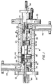
- the novel gas compressor 10 has a straight cylinder 12 which has a longitudinal axis 14 and a circumferential wall 16.
- a cylindrical sleeve 18 is set within the cylinder 12, and extends from one end of the cylinder 12 to substantially a mid-length thereof.
- a first, one-way valve assembly 20 is removably set within the cylinder 12, in adjacency to axial end 22 of the cylinder.
- a second, centrally-bored, one-way valve assembly 24 is set within the cylinder in adjacency to axial end 26 of the cylinder 12.
- Headers 28 and 30 close off ends 22 and 26, and are secured in place by tie rods (not shown), as more fully described in the aforesaid US-A-5,015,158.
- a piston rod 32 is reciprocably disposed within the cylinder 12 and the sleeve 18, and is in slidable penetration of the second valve assembly 24.
- the rod 32 has a terminal, drive end 34 which extends outwardly from the cylinder 12 for coupling thereof to a prime mover (not shown).
- a third, one-way valve assembly 36 is coupled to the innermost end of the rod 32, and a fourth, one-way valve assembly 38 is coupled to the rod 32 intermediate the length of the rod.
- Gas inlet radial porting 40 is formed in the wall 16, adjacent to end 22 of the cylinder 12, for admitting gas to the first valve assembly 20, and gas outlet radial porting 42 is formed in the wall 16 and the sleeve 18 for discharging compressed gas from the second valve assembly 24.
- a flanged conduit 44 is joined to porting 40, and a flanged conduit 46 is joined to porting 42.
- valve assemblies 20, 24, 36 and 38 are of the plate-type, and correspond to the valve assembly disclosed in the aforecited US-A-5,011,383.
- valve assembly 36 With reciprocation of the rod 32 in the right-hand direction (with reference to the Figure 1 depiction), valve assembly 36 will move toward the sleeve 18, and draw a vacuum between itself and valve assembly 20. As a consequence thereof, gas will be admitted through valve assembly 20 into a chamber 48. Then, with reciprocation of the rod 32 in the left-hand direction, the chamber-confined gas will be compressed to a first stage of compression between valve assemblies 20 and 36 and, at some given pressure threshold, will pass through valve assembly 36 and enter chamber 48.
- valve assembly 38 will draw a relative vacuum between itself and valve assembly 24, and with translation of valve assembly 38 to the left will pass the first stage-compressed gas therethrough, from chamber 48. Then, with movement of valve assembly 38 to the right, this gas product will be compressed, between valve assemblies 38 and 24, to a second stage of compression. At another pressure threshold, the final compressed gas product will pass through valve assembly 24 to exit via porting 42 and conduit 46.
- Valves 20, 24,-36 and 38 have pluralities of grooves 50 formed therein which nest sealing rings 52 therein. Consequently, the valve assemblies 36 and 38 serve the function of pistons (as more fully explained in cited US-A-5,011,383).
- the chamber 48 which with translation of the rod 32 varies in volume, comprises both (a) a first compression stage compressed gas volume, and (b) a second compression stage suction volume. Where there obtains a reason to intercool the product compressed gas, between the two stages of compression, the invention sets forth an alternative embodiment of the invention, as depicted in Figure 2.
- index numbers which are the same or similar to those displayed on Figure 1 denote same or similar components.
- Compressor 10a in Figure 2 is of construction similar to compressor 10 of Figure 1, except for its accommodation for intercooling.
- a fluid barrier Between valve assemblies three and four, i.e. assemblies 36 and 38, is a fluid barrier.
- the latter comprises a circular sealing element 54.
- Element 54 like the valve assemblies, carries sealing rings 52 in grooves 50 provided therefor. It seals between left-hand and right-hand portions of the compression cylinder 12, and is coupled to the rod 32 intermediate the valve assemblies 36 and 38.
- a first stage discharge porting 56 and conduit 58 (shown in phantom) open onto the inner of the cylinder 12 between the element 54 and valve assembly 36
- a second stage porting 60 and conduit 62 open onto the inner of the cylinder 12 between element 54 and valve assembly 38. It remains only to interconnect an appropriate cooling device, between conduits 58 and 62, to provide for the inter-stage cooling.
- valve assemblies 20, 24, 36 and 38 are constructed as disclosed in US-A-5,011,383. Clearly, however, valve assemblies 20 and 36 are of larger diameter than valve assemblies 24 and 38. Valve assemblies 20 and 36, though, are identical and interchangeable, and valve assemblies 24 and 38 also are identical and interchangeable.
- valve assembly 20 is mounted on a stub shaft 64.
- Shaft 64 has an outermost threaded end which is threadedly engaged with header 28 and receives a threaded cap nut 66 at the termination thereof. Too, stub shaft 64 has a hexagonal lug formed thereon intermediate the length thereof. The lug 68 can be engaged and turned by a wrench to adjust the positioning of valve assembly 20, as a means of varying the compression level to be achieved in the first stage of compression.
- the valve assembly 20 is horizontally split; the cross-sectioned half depicts the valve assembly 20 set in its innermost positioning, and the full-line half thereof depicts the same in its outermost positioning.
Landscapes
- Engineering & Computer Science (AREA)
- Mechanical Engineering (AREA)
- General Engineering & Computer Science (AREA)
- Compressor (AREA)
- Compressors, Vaccum Pumps And Other Relevant Systems (AREA)
Applications Claiming Priority (2)
| Application Number | Priority Date | Filing Date | Title |
|---|---|---|---|
| US07/899,805 US5209647A (en) | 1992-06-17 | 1992-06-17 | Straight cylinder gas compressor with a reduced diameter compression chamber |
| US899805 | 2010-10-07 |
Publications (2)
| Publication Number | Publication Date |
|---|---|
| EP0576133A1 true EP0576133A1 (de) | 1993-12-29 |
| EP0576133B1 EP0576133B1 (de) | 1996-09-25 |
Family
ID=25411587
Family Applications (1)
| Application Number | Title | Priority Date | Filing Date |
|---|---|---|---|
| EP93303753A Expired - Lifetime EP0576133B1 (de) | 1992-06-17 | 1993-05-14 | Gas-Verdichter |
Country Status (4)
| Country | Link |
|---|---|
| US (1) | US5209647A (de) |
| EP (1) | EP0576133B1 (de) |
| CN (1) | CN1034601C (de) |
| DE (1) | DE69305007T2 (de) |
Cited By (4)
| Publication number | Priority date | Publication date | Assignee | Title |
|---|---|---|---|---|
| WO1999024714A1 (en) * | 1997-11-07 | 1999-05-20 | Westport Research Inc. | High pressure fuel supply system for natural gas vehicles |
| US6659730B2 (en) | 1997-11-07 | 2003-12-09 | Westport Research Inc. | High pressure pump system for supplying a cryogenic fluid from a storage tank |
| EP1511935A4 (de) * | 2002-06-13 | 2006-01-18 | Dresser Rand Co | Gasverdichter und verfahren mit verbesserten ventilanordnungen |
| CN113969881A (zh) * | 2021-11-25 | 2022-01-25 | 郑州铁路职业技术学院 | 一种无电机直动型无油活塞式空气压缩机 |
Families Citing this family (10)
| Publication number | Priority date | Publication date | Assignee | Title |
|---|---|---|---|---|
| KR100399444B1 (ko) * | 1995-06-30 | 2004-04-29 | 주식회사 하이닉스반도체 | 에지강조형위상반전마스크및그제조방법 |
| US5658134A (en) * | 1995-07-26 | 1997-08-19 | J-Operating Company | Compressor with suction valve in piston |
| US5622486A (en) * | 1996-07-19 | 1997-04-22 | J-W Operating Company | Radially-valve compressor with adjustable clearance |
| US6318967B1 (en) | 2000-03-01 | 2001-11-20 | Dresser-Rand Company | Gas compression kit and method with interchangeable compression cylinders |
| US6655935B2 (en) * | 2002-01-14 | 2003-12-02 | Dresser-Rand Company | Gas compressor comprising a double acting piston, an elongate chamber, multiple inlets mounted within heads on both sides of the chamber, and one central outlet |
| DE102005034907A1 (de) * | 2005-07-26 | 2007-02-01 | Linde Ag | Verdichter, insbesondere Kolbenverdichter |
| CN101975150A (zh) * | 2010-10-26 | 2011-02-16 | 中国民航大学 | 双作用柱塞式除冰液泵 |
| CN103193833B (zh) * | 2013-03-28 | 2016-03-02 | 中国林业科学研究院林产化学工业研究所 | 生物质加压液化与定向萃取分离制备甲基糖苷和多酚产物的方法 |
| US9822877B2 (en) | 2013-09-16 | 2017-11-21 | Ariel Corporation | Lightweight compressor piston with opening |
| US20210079908A1 (en) | 2018-04-25 | 2021-03-18 | Dresser-Rand Company | Reciprocating compressor with improved valve cylinder assembly |
Citations (3)
| Publication number | Priority date | Publication date | Assignee | Title |
|---|---|---|---|---|
| US1488683A (en) * | 1922-07-05 | 1924-04-01 | Maximilian F Juruick | Compressor |
| NL38892C (de) * | 1935-05-09 | 1936-07-17 | ||
| US5015158A (en) * | 1989-11-08 | 1991-05-14 | Dresser-Rand Company | Gas compressor |
Family Cites Families (7)
| Publication number | Priority date | Publication date | Assignee | Title |
|---|---|---|---|---|
| US213692A (en) * | 1879-03-25 | Improvement in force-pumps | ||
| US2256926A (en) * | 1939-12-04 | 1941-09-23 | Maniscalco Pietro | Fluid compressor |
| US2323068A (en) * | 1941-03-29 | 1943-06-29 | Maniscalco Pictro | Compressor |
| US3694109A (en) * | 1970-12-09 | 1972-09-26 | Patrick Joseph Walls | Internal combustion engine or compressor |
| US4111609A (en) * | 1975-10-22 | 1978-09-05 | Anton Braun | Multistage gas compressor |
| JPH0733834B2 (ja) * | 1986-12-18 | 1995-04-12 | 株式会社宇野澤組鐵工所 | ロータ内蔵ハウジングの外周温度が安定化された内部分流逆流冷却多段式の三葉式真空ポンプ |
| US5011383A (en) * | 1990-01-02 | 1991-04-30 | Dresser-Rand Company | Valve assembly, for use in combination with a straight-cylinder, gas-compression chamber, and in combination therewith |
-
1992
- 1992-06-17 US US07/899,805 patent/US5209647A/en not_active Expired - Fee Related
-
1993
- 1993-04-28 CN CN93105331A patent/CN1034601C/zh not_active Expired - Fee Related
- 1993-05-14 DE DE69305007T patent/DE69305007T2/de not_active Expired - Fee Related
- 1993-05-14 EP EP93303753A patent/EP0576133B1/de not_active Expired - Lifetime
Patent Citations (3)
| Publication number | Priority date | Publication date | Assignee | Title |
|---|---|---|---|---|
| US1488683A (en) * | 1922-07-05 | 1924-04-01 | Maximilian F Juruick | Compressor |
| NL38892C (de) * | 1935-05-09 | 1936-07-17 | ||
| US5015158A (en) * | 1989-11-08 | 1991-05-14 | Dresser-Rand Company | Gas compressor |
Cited By (6)
| Publication number | Priority date | Publication date | Assignee | Title |
|---|---|---|---|---|
| WO1999024714A1 (en) * | 1997-11-07 | 1999-05-20 | Westport Research Inc. | High pressure fuel supply system for natural gas vehicles |
| US6659730B2 (en) | 1997-11-07 | 2003-12-09 | Westport Research Inc. | High pressure pump system for supplying a cryogenic fluid from a storage tank |
| US6898940B2 (en) | 2000-05-02 | 2005-05-31 | Westport Research Inc. | High pressure pump system for supplying a cryogenic fluid from a storage tank |
| EP1511935A4 (de) * | 2002-06-13 | 2006-01-18 | Dresser Rand Co | Gasverdichter und verfahren mit verbesserten ventilanordnungen |
| CN100513785C (zh) * | 2002-06-13 | 2009-07-15 | 德雷瑟尔-兰德公司 | 具有改进的阀组件的气体压缩机及方法 |
| CN113969881A (zh) * | 2021-11-25 | 2022-01-25 | 郑州铁路职业技术学院 | 一种无电机直动型无油活塞式空气压缩机 |
Also Published As
| Publication number | Publication date |
|---|---|
| EP0576133B1 (de) | 1996-09-25 |
| CN1034601C (zh) | 1997-04-16 |
| CN1080027A (zh) | 1993-12-29 |
| DE69305007T2 (de) | 1997-04-03 |
| DE69305007D1 (de) | 1996-10-31 |
| US5209647A (en) | 1993-05-11 |
Similar Documents
| Publication | Publication Date | Title |
|---|---|---|
| EP0576133A1 (de) | Gas-Verdichter | |
| US4334833A (en) | Four-stage gas compressor | |
| CA2487175C (en) | Gas compressor and method with improved valve assemblies | |
| WO2018065672A1 (en) | Gas intensifier with lubrication | |
| US4478561A (en) | Hydraulic intensifier | |
| CN110219793B (zh) | 一种二级压缩的无油活塞式压缩机 | |
| US6655935B2 (en) | Gas compressor comprising a double acting piston, an elongate chamber, multiple inlets mounted within heads on both sides of the chamber, and one central outlet | |
| EP0711918A3 (de) | Kältemittelverdichter mit veränderlicher Kapazität | |
| WO2005072127A2 (en) | Double-acting, high-pressure cryogenic pump | |
| US3713755A (en) | Pumping device | |
| US5525044A (en) | High pressure gas compressor | |
| CN109863300A (zh) | 具有入口折流件的液压泵 | |
| CA2092751C (en) | Gas compressor | |
| CN106523333A (zh) | 一种四缸隔膜式气体压缩机 | |
| CN118442279A (zh) | 一种往复式气体泵 | |
| RU2554162C2 (ru) | Газовый компрессор | |
| US2889108A (en) | Compressor | |
| CN208456793U (zh) | 往复式增压泵 | |
| CN220452184U (zh) | 油脂泵 | |
| WO2002025111A1 (en) | Reciprocating compressor driven by a linear motor | |
| CN111140461A (zh) | 一种水冷柱塞式多级压缩机及其配气机构 | |
| CN210196012U (zh) | 旋转压缩机及空调 | |
| CN212429126U (zh) | 用于直线压缩机的双气缸装置及直线压缩机 | |
| CN1149109A (zh) | 多级压力缸 | |
| KR20050043489A (ko) | 왕복동식 압축기의 흡입밸브 고정장치 |
Legal Events
| Date | Code | Title | Description |
|---|---|---|---|
| PUAI | Public reference made under article 153(3) epc to a published international application that has entered the european phase |
Free format text: ORIGINAL CODE: 0009012 |
|
| AK | Designated contracting states |
Kind code of ref document: A1 Designated state(s): DE ES FR GB NL |
|
| 17P | Request for examination filed |
Effective date: 19940521 |
|
| 17Q | First examination report despatched |
Effective date: 19950728 |
|
| GRAG | Despatch of communication of intention to grant |
Free format text: ORIGINAL CODE: EPIDOS AGRA |
|
| GRAH | Despatch of communication of intention to grant a patent |
Free format text: ORIGINAL CODE: EPIDOS IGRA |
|
| GRAH | Despatch of communication of intention to grant a patent |
Free format text: ORIGINAL CODE: EPIDOS IGRA |
|
| GRAA | (expected) grant |
Free format text: ORIGINAL CODE: 0009210 |
|
| AK | Designated contracting states |
Kind code of ref document: B1 Designated state(s): DE ES FR GB NL |
|
| PG25 | Lapsed in a contracting state [announced via postgrant information from national office to epo] |
Ref country code: ES Free format text: THE PATENT HAS BEEN ANNULLED BY A DECISION OF A NATIONAL AUTHORITY Effective date: 19960925 |
|
| REF | Corresponds to: |
Ref document number: 69305007 Country of ref document: DE Date of ref document: 19961031 |
|
| ET | Fr: translation filed | ||
| PLBE | No opposition filed within time limit |
Free format text: ORIGINAL CODE: 0009261 |
|
| STAA | Information on the status of an ep patent application or granted ep patent |
Free format text: STATUS: NO OPPOSITION FILED WITHIN TIME LIMIT |
|
| 26N | No opposition filed | ||
| REG | Reference to a national code |
Ref country code: GB Ref legal event code: IF02 |
|
| PGFP | Annual fee paid to national office [announced via postgrant information from national office to epo] |
Ref country code: NL Payment date: 20040416 Year of fee payment: 12 |
|
| PGFP | Annual fee paid to national office [announced via postgrant information from national office to epo] |
Ref country code: GB Payment date: 20040505 Year of fee payment: 12 |
|
| PGFP | Annual fee paid to national office [announced via postgrant information from national office to epo] |
Ref country code: FR Payment date: 20040519 Year of fee payment: 12 |
|
| PGFP | Annual fee paid to national office [announced via postgrant information from national office to epo] |
Ref country code: DE Payment date: 20040630 Year of fee payment: 12 |
|
| PG25 | Lapsed in a contracting state [announced via postgrant information from national office to epo] |
Ref country code: GB Free format text: LAPSE BECAUSE OF NON-PAYMENT OF DUE FEES Effective date: 20050514 |
|
| PG25 | Lapsed in a contracting state [announced via postgrant information from national office to epo] |
Ref country code: NL Free format text: LAPSE BECAUSE OF NON-PAYMENT OF DUE FEES Effective date: 20051201 Ref country code: DE Free format text: LAPSE BECAUSE OF NON-PAYMENT OF DUE FEES Effective date: 20051201 |
|
| GBPC | Gb: european patent ceased through non-payment of renewal fee |
Effective date: 20050514 |
|
| PG25 | Lapsed in a contracting state [announced via postgrant information from national office to epo] |
Ref country code: FR Free format text: LAPSE BECAUSE OF NON-PAYMENT OF DUE FEES Effective date: 20060131 |
|
| NLV4 | Nl: lapsed or anulled due to non-payment of the annual fee |
Effective date: 20051201 |
|
| REG | Reference to a national code |
Ref country code: FR Ref legal event code: ST Effective date: 20060131 |
|
| REG | Reference to a national code |
Ref country code: DE Ref legal event code: R082 Ref document number: 69305007 Country of ref document: DE Representative=s name: MAI DOERR BESIER PATENTANWAELTE, DE |