EP0578459A1 - Improvements relating to support systems for cables, service pipes and the like - Google Patents
Improvements relating to support systems for cables, service pipes and the like Download PDFInfo
- Publication number
- EP0578459A1 EP0578459A1 EP93305237A EP93305237A EP0578459A1 EP 0578459 A1 EP0578459 A1 EP 0578459A1 EP 93305237 A EP93305237 A EP 93305237A EP 93305237 A EP93305237 A EP 93305237A EP 0578459 A1 EP0578459 A1 EP 0578459A1
- Authority
- EP
- European Patent Office
- Prior art keywords
- cable
- sections
- ladder
- tray
- blank
- Prior art date
- Legal status (The legal status is an assumption and is not a legal conclusion. Google has not performed a legal analysis and makes no representation as to the accuracy of the status listed.)
- Withdrawn
Links
- 230000008878 coupling Effects 0.000 claims abstract description 19
- 238000010168 coupling process Methods 0.000 claims abstract description 19
- 238000005859 coupling reaction Methods 0.000 claims abstract description 19
- 239000000463 material Substances 0.000 claims abstract description 17
- 210000002105 tongue Anatomy 0.000 claims description 13
- 239000002184 metal Substances 0.000 claims description 7
- 238000009434 installation Methods 0.000 claims description 5
- 238000005452 bending Methods 0.000 claims description 4
- 238000003780 insertion Methods 0.000 claims description 2
- 230000037431 insertion Effects 0.000 claims description 2
- 238000004519 manufacturing process Methods 0.000 description 3
- 238000006073 displacement reaction Methods 0.000 description 2
- 229910001209 Low-carbon steel Inorganic materials 0.000 description 1
- 230000001934 delay Effects 0.000 description 1
- 230000014509 gene expression Effects 0.000 description 1
- 238000000034 method Methods 0.000 description 1
- 230000002093 peripheral effect Effects 0.000 description 1
Images


Classifications
-
- H—ELECTRICITY
- H02—GENERATION; CONVERSION OR DISTRIBUTION OF ELECTRIC POWER
- H02G—INSTALLATION OF ELECTRIC CABLES OR LINES, OR OF COMBINED OPTICAL AND ELECTRIC CABLES OR LINES
- H02G3/00—Installations of electric cables or lines or protective tubing therefor in or on buildings, equivalent structures or vehicles
- H02G3/02—Details
- H02G3/06—Joints for connecting lengths of protective tubing or channels, to each other or to casings, e.g. to distribution boxes; Ensuring electrical continuity in the joint
- H02G3/0608—Joints for connecting non cylindrical conduits, e.g. channels
Definitions
- This invention relates to support systems for cables, service pipes and the like and in particular concerns what is known as an accessory or coupler for cable trays and cable ladders.
- Cable support systems typically comprise what are known as cable trays and cable ladders, being elongated members defining a channel space for the receipt of the cables, the channel space being defined in the case of a cable tray by a base and cable tray sides, and in the case of cable ladder by ladder rungs extending between parallel ladder stringers.
- Accessories may be of T-configuration or cross configuration for the joining together of three lengths of cable tray or ladder or four lengths of cable tray ladder arranged at right angles to each other as the case may be.
- the present invention seeks to provide a novel form of accessory or coupler which is adjustable as to the angle between the respective coupling edges so that it can be used for any of a range of applications involving cable trays and cable ladders which are arranged at different angles.
- a device made of sheet material for connecting together the ends of two lengths of cable tray or cable ladder, comprising two or more sections which are channel shaped and of which the bases serve to support cables or the like, extending in use between the cable tray lengths, and of which sections two define edges respectively for coupling to the said cable trays or ladders, the sheet material of the device integrally connecting adjacent sections so that the sections are adjustable in relative angularly by bending said sheet material where it so connects the sections.
- the coupler or accessory includes means for locking the sections in any adjusted position.
- Adjacent sections may be angularly adjustable about a perpendicular axis, for coupling lengths of cable tray or cable ladder in a common plane.
- the respective bases of adjacent sections then preferably overlap.
- adjacent sections may be angularly adjustable about a transverse axis, for coupling lengths of cable tray or cable ladder inclined at different gradients.
- the fixing means may comprise a nut and bolt arrangement adapted to pass through the overlapping sections, one of which has a hole for the bolt and the other of which has a slot through which the bolt can slide when adjustment is taking place, said slot being arcuate and having its centre at location about which the sections are hingeable.
- a single strip of material defines the hinge point and also the walls of both sections at that side of the accessory, the material being of a ductile nature so as to be capable of defining a hinge.
- the entire accessory is formed from a blank of sheet material duly punched and cut from such material, the blank defining in each of said sections a base and outer and inner walls, which are folded at right angles relative to the base, and the outer walls are integral and are coupled by a section which forms the said hinge pivot.
- the blank will be of metal, and the respective inner walls will be provided with means whereby they can be coupled and anchored together when the blank is folded to define the accessory, and the sections have been angled one relative to another to suit the particular cable tray installation.
- edges for connection to the cable tray lengths or cable ladder lengths may be defined by base extensions which are joggled out of the plane of the base, so that the base will lie in the same plane as the adjacent cable tray, and the sides may be provided with coupling tongues adapted to overlap the side walls of the cable tray to which the edge is to be connected.
- the tongues may be profiled as set forth in our co-pending UK Patent Application No 9121518.6 for ease of insertion of the tongues into the return flange cable tray walls when the cable tray is of the return flange type.
- the blank 10 is of sheet metal such as mild steel, and may if desired be dip galvanised.
- the blank can be considered as having a centre line 12 insofar as it defines two sections 14 and 16 to opposite sides of the centre line 12, although the sections are not symmetrical as will be evident.
- Section 14 has a base 18 and an outer side wall 20 and an inner side wall 22, the expressions inner and outer being applied in relation to the manner in which the accessory is used as will be clear hereinafter.
- Each of the side walls 20 and 22 is provided with a fold over top flange 24 and 26, and at the left hand ends in Fig. 1, the side walls 20 and 22 are provided with identical location and connection tongues 28 and 30.
- the base at the left hand end has a joggled extension plate 32 which is displaced out of the plane of the base 18 by a joggling section 34 which is formed when the blank is cut and punched from the stock material.
- the base 18 is provided with a coupling plate 34, of a configuration shown and again joggled downwardly out of the plane of the base 18 by the joggled section 36.
- the coupling plate 34 is provided with a curved slot 38 whose centre of curvature is on the centre line, and in the vicinity of the section 40 which couples the outer walls of the sections 14 and 16.
- the section 16 is of generally similar configuration to the section 14, except that the connector plate 34 is omitted, and the inner side wall 44 is provided with fixing slot 46 and aperture 48.
- the slot 46 is arranged on the same radius of curvature as the slot 38 and the aperture 48 is arranged on the same radius of curvature as the apertures 42 so that as will be explained hereinafter when the blank is assembled, slot 38 registers with slot 46 and apertures 42 can be arranged to register with aperture 48.
- the blank is folded to an erected condition in order to render it suitable for forming the accessory which is shown in Fig. 2, and in the arrangement shown in Fig. 1 the fold lines are indicated by chain-dotted lines.
- the double dotted lines illustrate the joggled portions.
- the blank is furthermore punched with apertures as indicated.
- the side wall 44 is furthermore provided with a long extension tongue 50 having a slot 52 therein. Additionally, the side wall 22 of section 14 is provided with the registration slot 52 which registers with the slot 50 in the assembled condition of the accessory.
- the side walls of the sections are folded upwardly, and the flanges such as 24 and 26 of the side walls are folded inwardly as shown in Fig. 2.
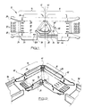
- Fig. 2 shows the accessory in the assembled condition, and a pair of return flange cable tray ends 56 and 58 adapted to be presented to and coupled to the coupling edges 60 and 62 defined at the free ends of the sections 14 and 16.
- Fig. 3 shows a further embodiment of the invention, in this case the accessory having three defined sections; tray connecting sections 70 and 74, and intermediate section 72.
- This three-section connector is similarly produced by erection from a single blank, and the end sections 70 and 74 have similar forms to that of section 14 in the two-section accessory, except that the connector plate 34 is omitted, and fixing slots 85 and 87 are provided in base plates 88 and 90 respectively.
- Middle section 72 comprises a base plate 86, connector plates 81 and 83 which overlap the base plates 88 and 90 of the end sections 70 and 74, and side wall 80 from which extension tongues 82 and 84 extend at either side.
- the end sections 88 and 90 are angularly adjustable relative to one another by deformation of the coupling portions 76 and 78 and extension tongues 82 and 84 respectively.
- the accessory is then locked in shape by the fitting of bolts 92 and 94 through slots 85 and 89, and 87 and 91 respectively in the overlapping base plates, and bolts 96 and 98 into the side walls and through the extension tongues.
- This embodiment has an advantage over the one-hinge embodiment in that considerably lens deformation occurs at each hinge, thus making the structure more durable.
- the embodiment shown in Fig. 3 also displays a greater range of angular positions possible and also provides a less edged connection, thus facilitating the positioning of cables within.
- An extremely effective and efficient coupling accessory is provided by the invention and is one which can be readily adjusted in an angular fashion to suit the angle of coupling between the trays 56 and 58 regardless of the angle at which the trays lie, as long as this angle is within the range of adjustment of the accessory.
- a similar type of strip-hinge arrangement might also be used in an accessory used to alter the gradient of cable tray or ladder arrangement, as shown in Figs. 5 and 6.
- the vertical riser 100 shown in Fig. 6 is divided into three sections 102, 104, 106 by a transverse arrangement of rectangular holes 108, defining hinge strips 110.
- the hinge strips 110 are positioned in the floor 112 of the accessory 100, as opposed to the previously described embodiments which provide lateral angular displacement in a plane, wherein the hinge strips are provided in the side-wall portions, e.g. side wall 25 of the embodiment shown in Fig. 2
- the factory process will, after blanking to the form shown in Fig. 5, include the steps of bending the side walls 114 to an upright position and inturning the wall flanges 116.
- the user simply bends the riser 100 into the multi-incline form desired. Only the strips 110 along the two transverse hinges 118 and 120 are deformed, and the upper corners of the separate side walls 114 are caused to overlap.
- the user attaches nuts 126 and bolts 128 in the respective holes 122 and arcuate slots 124 provided in the overlapping side walls 114.
- the riser ends 130 and 132 are adapted for connection to the ends of a cable ladder or tray.
- arcuate slots in the fixing arrangement allows the angular displacement of the riser to be variable through a range of angles. It will be appreciated that any number of hinges, e.g. 118, from only one upwards, can be provided and any suitable fixing means might be used. If the connecting strips 110 are sufficiently rigid or numerous, no separate fixing means may be required.
- a conversely-curved riser arrangement could be provided with suitable fixing means, e.g. side wall-like portions which are bent vertically downwards. These portions will overlap on bending the riser into shape, and will be provided with slots and holes in a similar fashion to those in the convavely-curved riser 100 side walls 114 to allow fixing into shape by the placement of bolts therein.
- suitable fixing means e.g. side wall-like portions which are bent vertically downwards.
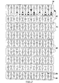
- a configuration of blank as shown in Fig. 7 is used.
- This cable riser blank 150 has nine riser sections 152, separated by eight lines of weakness 154.
- Each line of weakness 154 is defined by a row of slots 156 cut into the blank. The remainder of the perforations 158 on the blank are more widely spaced, so that the device will bend along the designated lines 154 when torque is applied.
- peripheral sections 160 are erected by machine labour at the manufacturing site to form side walls. It is however preferred that the predesignated hinge lines 154 are weak enough for the riser to be further formed manually at the site of installation.
Landscapes
- Engineering & Computer Science (AREA)
- Architecture (AREA)
- Civil Engineering (AREA)
- Structural Engineering (AREA)
- Details Of Indoor Wiring (AREA)
Abstract
A cable-tray or cable-ladder coupler which is adjustable as to the angle between the respective coupling edges is provided. The coupler is erected from a blank and two sections of it are relatively hingeable and may be locked in position. The hinge is constituted by a single strip of material and two overlapping pieces of sheet material are relatively slidable by means of a bolt guided in an arcuate slot.
Description
- This invention relates to support systems for cables, service pipes and the like and in particular concerns what is known as an accessory or coupler for cable trays and cable ladders.
- Cable support systems typically comprise what are known as cable trays and cable ladders, being elongated members defining a channel space for the receipt of the cables, the channel space being defined in the case of a cable tray by a base and cable tray sides, and in the case of cable ladder by ladder rungs extending between parallel ladder stringers.
- When it is necessary to couple one end of one length of cable tray or ladder with an end of another cable tray or cable ladder, unless the cable trays and cable ladders are in alignment and can be joined directly end to end, it is necessary to use an accessory or coupler designed with a pair of coupling edges adapted respectively to couple to the respective ends of the cable trays and cable ladders. Accessories may be of T-configuration or cross configuration for the joining together of three lengths of cable tray or ladder or four lengths of cable tray ladder arranged at right angles to each other as the case may be.
- It frequently happens however that in any particular installation, the lengths of cable tray or ladder will lie at an angle other than 90°, and it is usual in such circumstances to make a custom designed accessory or coupler with the coupling edges at the appropriate angle. As these accessories or couplers are fabricated from sheet metal in the majority of cases, so the custom manufacture of accessories and couplers can become an inconvenience and an expense.
- Additionally, if it is discovered on site that a coupler is not of the correct angle for the installation in question, then this can cause considerable delays in the erection of the system.
- The present invention seeks to provide a novel form of accessory or coupler which is adjustable as to the angle between the respective coupling edges so that it can be used for any of a range of applications involving cable trays and cable ladders which are arranged at different angles.
- According to one aspect of the present invention, there is provided a device made of sheet material for connecting together the ends of two lengths of cable tray or cable ladder, comprising two or more sections which are channel shaped and of which the bases serve to support cables or the like, extending in use between the cable tray lengths, and of which sections two define edges respectively for coupling to the said cable trays or ladders, the sheet material of the device integrally connecting adjacent sections so that the sections are adjustable in relative angularly by bending said sheet material where it so connects the sections.
- Preferably, the coupler or accessory includes means for locking the sections in any adjusted position.
- Adjacent sections may be angularly adjustable about a perpendicular axis, for coupling lengths of cable tray or cable ladder in a common plane. The respective bases of adjacent sections then preferably overlap.
- Alternatively, adjacent sections may be angularly adjustable about a transverse axis, for coupling lengths of cable tray or cable ladder inclined at different gradients. The fixing means may comprise a nut and bolt arrangement adapted to pass through the overlapping sections, one of which has a hole for the bolt and the other of which has a slot through which the bolt can slide when adjustment is taking place, said slot being arcuate and having its centre at location about which the sections are hingeable.
- In a particularly suitable arrangement, a single strip of material defines the hinge point and also the walls of both sections at that side of the accessory, the material being of a ductile nature so as to be capable of defining a hinge.
- In one embodiment, the entire accessory is formed from a blank of sheet material duly punched and cut from such material, the blank defining in each of said sections a base and outer and inner walls, which are folded at right angles relative to the base, and the outer walls are integral and are coupled by a section which forms the said hinge pivot.
- Typically the blank will be of metal, and the respective inner walls will be provided with means whereby they can be coupled and anchored together when the blank is folded to define the accessory, and the sections have been angled one relative to another to suit the particular cable tray installation.
- The edges for connection to the cable tray lengths or cable ladder lengths may be defined by base extensions which are joggled out of the plane of the base, so that the base will lie in the same plane as the adjacent cable tray, and the sides may be provided with coupling tongues adapted to overlap the side walls of the cable tray to which the edge is to be connected.
- The tongues may be profiled as set forth in our co-pending UK Patent Application No 9121518.6 for ease of insertion of the tongues into the return flange cable tray walls when the cable tray is of the return flange type.
- The invention is best explained in relation to embodiments thereof, illustrated in the accompanying drawings, wherein:-
- Fig. 1 is a plan view of a sheet metal blank erectable into an accessory according to an embodiment of the invention;
- Fig. 2 shows the blank of Fig. 1 in erected condition and arranged to receive the ends of respective cable tray lengths;
- Fig. 3 shows an erected accessory according to a further embodiment of the invention;
- Fig. 4 is a plan view of the sheet metal blank erectable into the accessary of Fig. 3;
- Fig. 5 is a plan view of a sheet metal blank erectable into a vertical riser according to yet a further embodiment of the invention;
- Fig. 6 shows the blank of Fig. 5 in erected condition; and
- Fig. 7 is a plan view of a cable riser blank according to another embodiment of the invention.
- Referring to the drawings, and firstly to Fig. 1, the blank 10 is of sheet metal such as mild steel, and may if desired be dip galvanised. The blank can be considered as having a
centre line 12 insofar as it defines twosections centre line 12, although the sections are not symmetrical as will be evident. -
Section 14 has abase 18 and anouter side wall 20 and aninner side wall 22, the expressions inner and outer being applied in relation to the manner in which the accessory is used as will be clear hereinafter. - Each of the
side walls top flange side walls connection tongues 28 and 30. - The base at the left hand end has a joggled extension plate 32 which is displaced out of the plane of the
base 18 by ajoggling section 34 which is formed when the blank is cut and punched from the stock material. - At the right hand end and towards the
centre line 12, thebase 18 is provided with acoupling plate 34, of a configuration shown and again joggled downwardly out of the plane of thebase 18 by thejoggled section 36. Thecoupling plate 34 is provided with acurved slot 38 whose centre of curvature is on the centre line, and in the vicinity of thesection 40 which couples the outer walls of thesections - Adjacent the
slot 38 areadditional fixing apertures 42. - As can be seen from Fig. 1, the
section 16 is of generally similar configuration to thesection 14, except that theconnector plate 34 is omitted, and theinner side wall 44 is provided with fixing slot 46 andaperture 48. The slot 46 is arranged on the same radius of curvature as theslot 38 and theaperture 48 is arranged on the same radius of curvature as theapertures 42 so that as will be explained hereinafter when the blank is assembled,slot 38 registers with slot 46 andapertures 42 can be arranged to register withaperture 48. - As will be appreciated from the foregoing description, the blank is folded to an erected condition in order to render it suitable for forming the accessory which is shown in Fig. 2, and in the arrangement shown in Fig. 1 the fold lines are indicated by chain-dotted lines. The double dotted lines illustrate the joggled portions.
- The blank is furthermore punched with apertures as indicated.
- The
side wall 44 is furthermore provided with along extension tongue 50 having aslot 52 therein. Additionally, theside wall 22 ofsection 14 is provided with theregistration slot 52 which registers with theslot 50 in the assembled condition of the accessory. - In order to assemble the accessory, the side walls of the sections are folded upwardly, and the flanges such as 24 and 26 of the side walls are folded inwardly as shown in Fig. 2.
- To angle the
respective sections section 40 so that thecoupling plate 38 slides underneath the base of thesection 16, and the slots andapertures slots 38 and 46 to anchor the sections in the angled position. Thelong tongue 50 is positioned to the inside ofside 22 but between theside 22 and theflange 26 as shown in Fig. 2, and then a bolt 54 is passed through the alignedslots tongue 50 in the adjusted position. The tongue has to be bent so as to follow the angularity between thesections - Fig. 2 shows the accessory in the assembled condition, and a pair of return flange
cable tray ends coupling edges sections - Fig. 3 shows a further embodiment of the invention, in this case the accessory having three defined sections; tray connecting
sections intermediate section 72. This three-section connector is similarly produced by erection from a single blank, and theend sections section 14 in the two-section accessory, except that theconnector plate 34 is omitted, andfixing slots base plates -
Middle section 72 comprises abase plate 86, connector plates 81 and 83 which overlap thebase plates end sections side wall 80 from whichextension tongues - The
end sections coupling portions extension tongues bolts 92 and 94 throughslots bolts - An extremely effective and efficient coupling accessory is provided by the invention and is one which can be readily adjusted in an angular fashion to suit the angle of coupling between the
trays - A similar type of strip-hinge arrangement might also be used in an accessory used to alter the gradient of cable tray or ladder arrangement, as shown in Figs. 5 and 6. The
vertical riser 100 shown in Fig. 6 is divided into threesections rectangular holes 108, defininghinge strips 110. In the case of avertical riser 100, thehinge strips 110 are positioned in thefloor 112 of theaccessory 100, as opposed to the previously described embodiments which provide lateral angular displacement in a plane, wherein the hinge strips are provided in the side-wall portions, e.g. side wall 25 of the embodiment shown in Fig. 2 - In manufacture, the factory process will, after blanking to the form shown in Fig. 5, include the steps of bending the
side walls 114 to an upright position and inturning thewall flanges 116. In use, the user simply bends theriser 100 into the multi-incline form desired. Only thestrips 110 along the twotransverse hinges separate side walls 114 are caused to overlap. To fix the arrangement in shape, the user attachesnuts 126 andbolts 128 in therespective holes 122 andarcuate slots 124 provided in the overlappingside walls 114. Theriser ends - The use of arcuate slots in the fixing arrangement allows the angular displacement of the riser to be variable through a range of angles. It will be appreciated that any number of hinges, e.g. 118, from only one upwards, can be provided and any suitable fixing means might be used. If the connecting
strips 110 are sufficiently rigid or numerous, no separate fixing means may be required. - Further, a conversely-curved riser arrangement could be provided with suitable fixing means, e.g. side wall-like portions which are bent vertically downwards. These portions will overlap on bending the riser into shape, and will be provided with slots and holes in a similar fashion to those in the convavely-
curved riser 100side walls 114 to allow fixing into shape by the placement of bolts therein. - In a further embodiment of cable riser according to the invention, a configuration of blank as shown in Fig. 7 is used. This
cable riser blank 150 has nineriser sections 152, separated by eight lines ofweakness 154. Each line ofweakness 154 is defined by a row ofslots 156 cut into the blank. The remainder of theperforations 158 on the blank are more widely spaced, so that the device will bend along the designatedlines 154 when torque is applied. - The
peripheral sections 160 are erected by machine labour at the manufacturing site to form side walls. It is however preferred that thepredesignated hinge lines 154 are weak enough for the riser to be further formed manually at the site of installation.
Claims (12)
- A device made of sheet material for connecting together the ends of two lengths of cable tray or cable ladder, comprising two or more sections which are channel shaped and of which the bases serve to support cables or the like extending in use between the cable tray lengths, and of which sections two define edges respectively for coupling to the said cable trays or ladders, the sheet material of the device integrally connecting adjacent sections so that the sections are adjustable in relative angularly by bending said sheet material where it so connects the sections.
- A device according to claim 1 wherein adjacent sections are angularly adjustable about a perpendicular axis, for coupling lengths of cable tray or cable ladder in a common plane.
- A device according to Claim 1 wherein adjacent sections are angularly adjustable about a transverse axis for coupling lengths of cable tray or cable ladder inclined at different gradients.
- A device according to claim 1, 2 or 3, including means for locking the sections in any adjusted position.
- A device according to claim 4, the fixing means comprising one or more nut and bolt arrangements adapted to pass through each pair of overlapping sections, one of which having a hole for the bolt and the other having a slot through which the bolt can slide when adjustment is taking place, said slot being arcuate and having its centre of curvature at location about which the sections are hingeable.
- A device according to any of claims 1 to 5, wherein a line of weakness built into the device defines each hinge, the material of the device at each hinge being of a deformable nature.
- A device according to Claim 6, wherein the lines of weakness are created in the material by the positioning of slots along the said lines.
- A device according to any of claims 1 to 7, wherein the entire device is formed from a blank of sheet material duly punched and cut from such material, the blank defining in each of said sections a base and outer and inner walls, which are folded at right angles relative to the base, and the outer walls are integral.
- A device according to any of claims 1, 2, 4, 5 or 6, wherein the respective inner walls are provided with means whereby they can be coupled and anchored together when the blank is folded to define the device, and the sections have been angled one relative the other to suit the particular cable tray or cable ladder installation.
- A device according to any of claims 1 to 8, wherein the edges for connection to the cable-tray or cable-ladder lengths may be defined by base extensions which are joggled out of the plane of the base, so that the base will lie in the same plane as the adjacent cable tray or cable ladder, and the sides are provided with coupling tongues adapted to overlap the side walls of the cable tray or cable ladder to which the edge is to be connected.
- A device according to claim 10, wherein the tongues are suitably profiled for ease of insertion into cable-tray or cable-ladder walls of the return flange type.
- A device according to any of claims 1 to 11, wherein the blank is of metal.
Applications Claiming Priority (2)
| Application Number | Priority Date | Filing Date | Title |
|---|---|---|---|
| GB929214258A GB9214258D0 (en) | 1992-07-04 | 1992-07-04 | Improvements relating to support systems for cables,service pipes and the like |
| GB9214258 | 1992-07-04 |
Publications (1)
| Publication Number | Publication Date |
|---|---|
| EP0578459A1 true EP0578459A1 (en) | 1994-01-12 |
Family
ID=10718223
Family Applications (1)
| Application Number | Title | Priority Date | Filing Date |
|---|---|---|---|
| EP93305237A Withdrawn EP0578459A1 (en) | 1992-07-04 | 1993-07-01 | Improvements relating to support systems for cables, service pipes and the like |
Country Status (2)
| Country | Link |
|---|---|
| EP (1) | EP0578459A1 (en) |
| GB (1) | GB9214258D0 (en) |
Cited By (28)
| Publication number | Priority date | Publication date | Assignee | Title |
|---|---|---|---|---|
| EP0712189A1 (en) * | 1994-11-10 | 1996-05-15 | Stago B.V. | Raceway system composed of parts such as raceway elements and fittings for horizontal and vertical branches for accomondating cables, leads and the like |
| GB2315924A (en) * | 1996-07-26 | 1998-02-11 | Marshall C & C Ltd | Trunking corner piece |
| WO2002086576A1 (en) * | 2001-04-25 | 2002-10-31 | Adc Telecommunications, Inc. | Articulated trough system for communication cables |
| US6478499B1 (en) * | 2000-08-03 | 2002-11-12 | Panduit Corp. | Adjustable corner fitting |
| FR2831724A1 (en) * | 2001-10-31 | 2003-05-02 | Seine Const Elec | CONNECTION DEVICE FOR CABLE PATH AND ASSEMBLY OF CABLE PATH INCLUDING SUCH A CONNECTION DEVICE |
| GB2383767A (en) * | 2002-01-08 | 2003-07-09 | Parkin Woods Services Ltd | Method and apparatus for bending cable tray |
| NL1024866C2 (en) * | 2003-11-25 | 2005-05-27 | Johannes Reijnen | Cable or flexible conduit channel part is for support of at least one cable or conduit and comprises a support surface and at least one side wall extending crossways to one edge of the support surface |
| EP1617535A1 (en) * | 2004-07-15 | 2006-01-18 | Legrand | Flat angle or derivation device adaptable for different angles formed between cable ducts |
| EP1788681A3 (en) * | 2005-11-18 | 2009-04-22 | Interflex, S.A. | Engageable stretch of cable trays |
| GB2458749A (en) * | 2008-04-04 | 2009-10-07 | Schneider Electric Espana Sa | A quick connecting joint for adjoining cable trays |
| EP2211436A1 (en) * | 2009-01-26 | 2010-07-28 | Gewiss France SAS | Sheet-metal chute for cable raceway |
| CN102773672A (en) * | 2012-08-09 | 2012-11-14 | 天津二十冶建设有限公司 | Production method of cable tray bend without damaging zinc coating |
| EP2685576A1 (en) * | 2012-07-10 | 2014-01-15 | OBO Bettermann GmbH & Co. KG | Cable channel segment |
| EP2996214A1 (en) * | 2014-09-15 | 2016-03-16 | OBO Bettermann GmbH & Co. KG | Cable support segment connector as adapter for a cable support system |
| DE102016102351A1 (en) * | 2016-02-11 | 2017-08-17 | PUK Group GmbH & Co. KG | Connecting device for position-flexible, mechanical connection of cable guides and cable guide device with variable angle adjustment |
| DE202017101317U1 (en) * | 2017-03-08 | 2018-06-11 | Werner Wildeboer | Fluidic installation |
| EP3540883A1 (en) | 2018-03-16 | 2019-09-18 | Niedax GmbH & Co. KG | Cable guidance connector and method for connecting cable guidance elements |
| EP3681001A1 (en) * | 2019-01-09 | 2020-07-15 | Hermi, d.o.o. | Cable tray connecting device |
| CN111697484A (en) * | 2020-05-28 | 2020-09-22 | 国网黑龙江省电力有限公司大庆供电公司 | Aerial cable maintenance operation supporting table |
| WO2021105534A1 (en) * | 2019-11-28 | 2021-06-03 | Basor Electric, S.A. | Multi-position hinge for the angular connection of two cable trays |
| WO2021152191A1 (en) * | 2020-01-30 | 2021-08-05 | Aiscan, S.L. | Sheet-metal tray module for cable ducts and similar, and template piece for configuring the tray module |
| FR3112036A1 (en) * | 2020-06-26 | 2021-12-31 | Speedinnov | Cable tray suitable for a curved profile |
| CN114243597A (en) * | 2021-12-23 | 2022-03-25 | 江苏瑞仕达电气设备有限公司 | Cable bridge convenient to angle of adjustment |
| GB2601763A (en) * | 2020-12-09 | 2022-06-15 | Clifton George Miller Lloyd | Apparatus for elevated cabling |
| US20230350148A1 (en) * | 2022-05-02 | 2023-11-02 | Clearfield, Inc. | Flexible cable mounting systems |
| US12009646B2 (en) | 2018-05-07 | 2024-06-11 | A Raymond Et Cie | Device for accommodating a cable assembly |
| US12444914B2 (en) | 2016-02-25 | 2025-10-14 | T&B Cable Tray Canada Ltd. | Splice plate assembly for cable tray |
| WO2026013322A1 (en) * | 2024-07-08 | 2026-01-15 | Enrique Llorens Ciurana S.L | Curved guide tray for electrical installations |
Families Citing this family (1)
| Publication number | Priority date | Publication date | Assignee | Title |
|---|---|---|---|---|
| CN116191297B (en) * | 2023-05-04 | 2023-08-22 | 国网山东省电力公司肥城市供电公司 | Power supply cable laying assembly |
Citations (5)
| Publication number | Priority date | Publication date | Assignee | Title |
|---|---|---|---|---|
| FR365954A (en) * | 1906-05-07 | 1906-09-24 | Clarence Clifford Sibley | Elbow for electrical piping |
| US2656999A (en) * | 1951-11-15 | 1953-10-27 | T J Cope Inc | Angle connector for trough systems |
| FR1471497A (en) * | 1966-03-15 | 1967-03-03 | Rieth & Co Fa | Advanced cable trunking |
| EP0315023A2 (en) * | 1987-11-03 | 1989-05-10 | Swifts Of Scarborough Limited | Improvements relating to cable tray systems |
| GB2250564A (en) * | 1990-10-12 | 1992-06-10 | Rich Muller Limited | Fishplate |
-
1992
- 1992-07-04 GB GB929214258A patent/GB9214258D0/en active Pending
-
1993
- 1993-07-01 EP EP93305237A patent/EP0578459A1/en not_active Withdrawn
Patent Citations (5)
| Publication number | Priority date | Publication date | Assignee | Title |
|---|---|---|---|---|
| FR365954A (en) * | 1906-05-07 | 1906-09-24 | Clarence Clifford Sibley | Elbow for electrical piping |
| US2656999A (en) * | 1951-11-15 | 1953-10-27 | T J Cope Inc | Angle connector for trough systems |
| FR1471497A (en) * | 1966-03-15 | 1967-03-03 | Rieth & Co Fa | Advanced cable trunking |
| EP0315023A2 (en) * | 1987-11-03 | 1989-05-10 | Swifts Of Scarborough Limited | Improvements relating to cable tray systems |
| GB2250564A (en) * | 1990-10-12 | 1992-06-10 | Rich Muller Limited | Fishplate |
Cited By (37)
| Publication number | Priority date | Publication date | Assignee | Title |
|---|---|---|---|---|
| EP0712189A1 (en) * | 1994-11-10 | 1996-05-15 | Stago B.V. | Raceway system composed of parts such as raceway elements and fittings for horizontal and vertical branches for accomondating cables, leads and the like |
| GB2315924A (en) * | 1996-07-26 | 1998-02-11 | Marshall C & C Ltd | Trunking corner piece |
| GB2315924B (en) * | 1996-07-26 | 2000-09-06 | Marshall C & C Ltd | Trunking corner piece |
| US6478499B1 (en) * | 2000-08-03 | 2002-11-12 | Panduit Corp. | Adjustable corner fitting |
| WO2002086576A1 (en) * | 2001-04-25 | 2002-10-31 | Adc Telecommunications, Inc. | Articulated trough system for communication cables |
| US6585195B2 (en) | 2001-04-25 | 2003-07-01 | Adc Telecommunications, Inc. | Cable management system including variable segments |
| FR2831724A1 (en) * | 2001-10-31 | 2003-05-02 | Seine Const Elec | CONNECTION DEVICE FOR CABLE PATH AND ASSEMBLY OF CABLE PATH INCLUDING SUCH A CONNECTION DEVICE |
| EP1309058A1 (en) * | 2001-10-31 | 2003-05-07 | Société de Constructions Electriques de la Seine ( CES) | Connection device for cable ducts and cable ducts using the same |
| GB2383767A (en) * | 2002-01-08 | 2003-07-09 | Parkin Woods Services Ltd | Method and apparatus for bending cable tray |
| GB2383767B (en) * | 2002-01-08 | 2004-12-08 | Parkin Woods Services Ltd | Method and apparatus for bending cable tray |
| NL1024866C2 (en) * | 2003-11-25 | 2005-05-27 | Johannes Reijnen | Cable or flexible conduit channel part is for support of at least one cable or conduit and comprises a support surface and at least one side wall extending crossways to one edge of the support surface |
| EP1617535A1 (en) * | 2004-07-15 | 2006-01-18 | Legrand | Flat angle or derivation device adaptable for different angles formed between cable ducts |
| FR2873241A1 (en) * | 2004-07-15 | 2006-01-20 | Legrand Sa | DEVICE FOR FLAT ANGLE OR DERIVATION ADAPTABLE TO DIFFERENT ANGLES SHAPED BETWEEN CHUTE |
| EP1788681A3 (en) * | 2005-11-18 | 2009-04-22 | Interflex, S.A. | Engageable stretch of cable trays |
| GB2458749A (en) * | 2008-04-04 | 2009-10-07 | Schneider Electric Espana Sa | A quick connecting joint for adjoining cable trays |
| GB2458749B (en) * | 2008-04-04 | 2012-06-27 | Schneider Electric Espaa A S A | Quick connecting joint for electric wiring |
| EP2211436A1 (en) * | 2009-01-26 | 2010-07-28 | Gewiss France SAS | Sheet-metal chute for cable raceway |
| EP2685576A1 (en) * | 2012-07-10 | 2014-01-15 | OBO Bettermann GmbH & Co. KG | Cable channel segment |
| CN102773672A (en) * | 2012-08-09 | 2012-11-14 | 天津二十冶建设有限公司 | Production method of cable tray bend without damaging zinc coating |
| EP2996214A1 (en) * | 2014-09-15 | 2016-03-16 | OBO Bettermann GmbH & Co. KG | Cable support segment connector as adapter for a cable support system |
| DE102016102351A1 (en) * | 2016-02-11 | 2017-08-17 | PUK Group GmbH & Co. KG | Connecting device for position-flexible, mechanical connection of cable guides and cable guide device with variable angle adjustment |
| US12444914B2 (en) | 2016-02-25 | 2025-10-14 | T&B Cable Tray Canada Ltd. | Splice plate assembly for cable tray |
| DE202017101317U1 (en) * | 2017-03-08 | 2018-06-11 | Werner Wildeboer | Fluidic installation |
| EP3540883A1 (en) | 2018-03-16 | 2019-09-18 | Niedax GmbH & Co. KG | Cable guidance connector and method for connecting cable guidance elements |
| US12009646B2 (en) | 2018-05-07 | 2024-06-11 | A Raymond Et Cie | Device for accommodating a cable assembly |
| EP3681001A1 (en) * | 2019-01-09 | 2020-07-15 | Hermi, d.o.o. | Cable tray connecting device |
| WO2021105534A1 (en) * | 2019-11-28 | 2021-06-03 | Basor Electric, S.A. | Multi-position hinge for the angular connection of two cable trays |
| US12060740B2 (en) | 2019-11-28 | 2024-08-13 | Basor Electric, S.A. | Multi-position hinge for the angular connection of two cable trays |
| WO2021152191A1 (en) * | 2020-01-30 | 2021-08-05 | Aiscan, S.L. | Sheet-metal tray module for cable ducts and similar, and template piece for configuring the tray module |
| CN111697484B (en) * | 2020-05-28 | 2023-07-25 | 国网黑龙江省电力有限公司大庆供电公司 | High-altitude cable maintenance operation supporting table |
| CN111697484A (en) * | 2020-05-28 | 2020-09-22 | 国网黑龙江省电力有限公司大庆供电公司 | Aerial cable maintenance operation supporting table |
| FR3112036A1 (en) * | 2020-06-26 | 2021-12-31 | Speedinnov | Cable tray suitable for a curved profile |
| GB2601763A (en) * | 2020-12-09 | 2022-06-15 | Clifton George Miller Lloyd | Apparatus for elevated cabling |
| CN114243597A (en) * | 2021-12-23 | 2022-03-25 | 江苏瑞仕达电气设备有限公司 | Cable bridge convenient to angle of adjustment |
| US20230350148A1 (en) * | 2022-05-02 | 2023-11-02 | Clearfield, Inc. | Flexible cable mounting systems |
| US12153274B2 (en) * | 2022-05-02 | 2024-11-26 | Clearfield, Inc. | Flexible cable mounting systems |
| WO2026013322A1 (en) * | 2024-07-08 | 2026-01-15 | Enrique Llorens Ciurana S.L | Curved guide tray for electrical installations |
Also Published As
| Publication number | Publication date |
|---|---|
| GB9214258D0 (en) | 1992-08-19 |
Similar Documents
| Publication | Publication Date | Title |
|---|---|---|
| EP0578459A1 (en) | Improvements relating to support systems for cables, service pipes and the like | |
| EP0315023A2 (en) | Improvements relating to cable tray systems | |
| US5653079A (en) | Truss bracket | |
| US5165213A (en) | Partition wall and interlocking panels therefor | |
| CA2266182C (en) | Mounting bracket and supporting brace | |
| US6076325A (en) | Metal truss joining gusset | |
| US20170342736A1 (en) | Track system for supporting wall studs | |
| US6237300B1 (en) | Wall stud connectors | |
| NZ510447A (en) | Clip fastening system for walls where each clip has a resilient detent | |
| US7065928B1 (en) | Roof curb assembly | |
| US6237301B1 (en) | Flexible runner | |
| US20050086896A1 (en) | Multiple flexible track | |
| CA2212344C (en) | Flexible runner | |
| EP0613408A1 (en) | Developed blank layout angle bracket | |
| US4678018A (en) | Screen arrangement | |
| US20040074200A1 (en) | Metal framing member with off site manufactured layout locating tabs | |
| US20050166524A1 (en) | Metal framing member with off site manufactured locking tabs | |
| GB2267605A (en) | Cable tray bridging members | |
| IE77168B1 (en) | Partition frame structure | |
| JP2710087B2 (en) | Construction method of the horizontal roof exterior | |
| CA2559322C (en) | Post coupler | |
| US11767672B2 (en) | Modular building construction | |
| EP0579929A1 (en) | Improvements relating to supporting brackets | |
| EP1409805A1 (en) | Partially rigid channel section having close transversal notches and a continuous longitudinal ribbing located on the base flange between the discontinuous side flanges | |
| CA2296703A1 (en) | Improvements relating to connection devices |
Legal Events
| Date | Code | Title | Description |
|---|---|---|---|
| PUAI | Public reference made under article 153(3) epc to a published international application that has entered the european phase |
Free format text: ORIGINAL CODE: 0009012 |
|
| AK | Designated contracting states |
Kind code of ref document: A1 Designated state(s): DE FR GB IT NL SE |
|
| 17P | Request for examination filed |
Effective date: 19940609 |
|
| 17Q | First examination report despatched |
Effective date: 19951206 |
|
| STAA | Information on the status of an ep patent application or granted ep patent |
Free format text: STATUS: THE APPLICATION IS DEEMED TO BE WITHDRAWN |
|
| 18D | Application deemed to be withdrawn |
Effective date: 19960417 |