EP0579273A1 - Apparat zum Wiederüberziehen gespleisster Längen der zu überziehenden optischen Fasern - Google Patents
Apparat zum Wiederüberziehen gespleisster Längen der zu überziehenden optischen Fasern Download PDFInfo
- Publication number
- EP0579273A1 EP0579273A1 EP93114473A EP93114473A EP0579273A1 EP 0579273 A1 EP0579273 A1 EP 0579273A1 EP 93114473 A EP93114473 A EP 93114473A EP 93114473 A EP93114473 A EP 93114473A EP 0579273 A1 EP0579273 A1 EP 0579273A1
- Authority
- EP
- European Patent Office
- Prior art keywords
- recoating
- end portions
- portions
- spliced
- recoated
- Prior art date
- Legal status (The legal status is an assumption and is not a legal conclusion. Google has not performed a legal analysis and makes no representation as to the accuracy of the status listed.)
- Granted
Links
Images


Classifications
-
- G—PHYSICS
- G02—OPTICS
- G02B—OPTICAL ELEMENTS, SYSTEMS OR APPARATUS
- G02B6/00—Light guides; Structural details of arrangements comprising light guides and other optical elements, e.g. couplings
- G02B6/24—Coupling light guides
-
- G—PHYSICS
- G02—OPTICS
- G02B—OPTICAL ELEMENTS, SYSTEMS OR APPARATUS
- G02B6/00—Light guides; Structural details of arrangements comprising light guides and other optical elements, e.g. couplings
- G02B6/24—Coupling light guides
- G02B6/255—Splicing of light guides, e.g. by fusion or bonding
- G02B6/2558—Reinforcement of splice joint
-
- G—PHYSICS
- G02—OPTICS
- G02B—OPTICAL ELEMENTS, SYSTEMS OR APPARATUS
- G02B6/00—Light guides; Structural details of arrangements comprising light guides and other optical elements, e.g. couplings
- G02B6/24—Coupling light guides
- G02B6/36—Mechanical coupling means
- G02B6/38—Mechanical coupling means having fibre to fibre mating means
- G02B6/3801—Permanent connections, i.e. wherein fibres are kept aligned by mechanical means
Definitions
- This invention relates to an apparatus for recoating end portions of lengths of coated optical fibers as set forth in the preamble of claim 1
- a method of recoating spliced end portions of optical fibers is disclosed in U.S. Pat. No. 4,410,561.
- the method involves placing the spliced fiber end portions from which the original coating material has been removed and adjacent portions within a cavity in the form of a groove in a split mold.
- the effective diameter of the groove is somewhat greater than that of the remaining coated portion of each fiber.
- the fibers are positioned so that only portions of the coated portions of the fibers touch the surface which defines the groove, while the vulnerable, uncoated spliced end portions of the fibers remain suspended and do not contact the groove surface.
- the mold is covered to enclose the groove and a suitable curable coating material is injected into the groove to recoat the bared, spliced fiber end portions.
- the recoating material contacts the adjacent originally coated portions of the spliced fibers along substantially radial planes exposed when the original coating material was removed from the end portions and along overlapping portions of the outer surface of the original coating material adjacent to the radial planes.
- the coating material is then cured to yield a recoated splice section with a transverse cross section which is larger than that of the optical fiber having the original coating material thereon.
- This molding process provides a recoated splice; however, steps must be taken to avoid an undesirable number of residual bubbles in the recoating material.
- the existence of bubbles may lead to stress concentrations when the fiber is handled subsequently. This is particularly undesirable in underwater cables where splices are inaccessible and under stress for many years.
- US-PS 4410561 discloses an apparatus for recoating bared end portions of optical fibers which have been spliced together. This apparatus is adapted to avoid the formation of bubbles in the coating material.Therefore the spliced portions of the fibers are positioned in a groove of a mold base plate and enclosed with a cover. An UV-energy source is used to cure the recoating material encapsulating the bared end portion of optical fibers. As the UV radiation is directed past the recoated spliced end portions it is reflected by means of a plane base plate. The reflected radiation can not be directed to the underside of the recoating material which causes an uneven curing of the recoating material..
- the sought after apparatus which are to be used to recoat spliced end portions of optical fibers preferably are such that the formation of bubbles is avoided substantially.
- the coating material on end portions of the lengths of each of two coated optical fibers is removed to leave a bared portion and a portion on which the coating material is conically shaped.
- the prepared end portions which have been spliced together are positioned in a passageway of a fixture with original coated portions of the lengths adjacent to the end portions being held in opposed vacuum chucks at opposite ends of the fixture.
- An injection port communicates a supply of a curable recoating material with the passageway.
- the passageway is formed in a mold block of material which is transparent to radiation used to cure the recoating material.
- the mold block of material is supported on a metallic pedestal. Along an upper surface of the pedestal is provided a trough which is in alignment with the passageway and spaced therefrom and which includes a polished reflective surface.
- the apparatus of this invention assure that the recoating material which covers the spliced portions of the lengths of coated optical fibers are cured uniformly.
- a curable recoating material After a curable recoating material has been injected through the port into the passageway and caused to encapsulate the bared and tapered portions of the end portions, it is cured by exposing it to suitable radiation.
- the trough in the metallic pedestal has a transverse cross section which is parabolic.
- the passageway is positioned at the focal point of the parabolic cross section of the trough so that radiation extending past the coated optical fiber is reflected by the wall of the trough and caused to engage the peripheral portion of the coated optical fiber which is not exposed directly to the radiation. As a result, the entire periphery of the recoated optical fiber portions in the passageway is cured uniformly.
- the coated optical fibers 32-33 are well known and each includes an optical fiber 36 having a coating material 38 applied thereon (see FIG. 4). As is well known, the optical fiber 36 includes a core and a cladding. An outer diameter of the coated optical fiber is on the order of 250 microns.
- the bared end portions 30-y30 from which the coating material 38 has been removed at least partially have been spliced together by a technique such as fusion bonding which is disclosed in an article entitled "Optical Fiber Joining Technique" which was authored by D. L. Bisbee and which appeared beginning at page 3153 of Vol. 50 No. 10 of the December 1971 issue of the Bell System Technical Journal. Each end portion 30 has a length of about 1,27 cm (0,5 inch).
- the spliced end portions 30-30 are recoated in accordance with the apparatus of this invention.
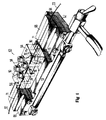
- the apparatus 60 includes a base 62 which includes two ways 64 and 66 spaced along a longitudinal axis of the base. Mounted in each of the ways 64 and 66 is a vacuum chuck 68. Each chuck 68 includes a groove 71 which extends generally parallel to the longitudinal axis of the base. Each of the grooves 71-71 has a transverse cross section such that it is capable of holding a length of coated optical fiber. Further, the wall of each of the grooves 71-71 is connected to a source of vacuum (not shown) to hold a coated optical fiber in the groove during the recoating process.
- a center portion 73 of the base 60 is raised somewhat over adjacent portions.
- the center portion 73 includes a longitudinally extending trough 75 which in transverse cross section has a parabolic configuration.
- This trough 75 is referred to as a reflective chamber and typically is milled in a base which is made of aluminium.
- the surface of the trough 75 is polished.
- the mold block 80 Supported on the center portion 73 is a mold block 80 (see FIGS. 1 and 2).
- the mold block 80 includes a longitudinal extending groove 82 which is adapted to hold the spliced end portions of two lengths of coatedoptical fibers.
- Projecting upwardly from two corners of the mold block 80 are two alignment pins 84-84.
- the alignment pins 84-84 are used to align a top mold block 90 with the mold block 80.
- the mold blocks are made from a material which is transparent to ultraviolet (UV) radiation such as Plexiglas UV transparent material or equivalent resin material or quartz, for example.
- the top mold block 90 also includes a longitudinally extending groove 92 which is adapted to cooperate with the groove 82 in the mold block 80 to provide a passageway 93 to enclose the spliced end portions of the two lengths of coated optical fibers. Further, the top mold block 90 is secured to the mold block 80 to provide a close fitting groove for those end portions by four bolts 94-94, or other suitable clamping means.
- passageway 93 communicates with an injection nozzle 96 (see FIG. 1).
- the injection nozzle 96 is connected to a supply of recoating material which preferably is the same material which was used to coat the drawn fiber.
- a material may be a UV curable acrylate material, for example.
- Portions of the spliced lengths 32 and 33 of the coated optical fibers adjacent to the end portions 30-30 are caused to be received in the grooves 71-71 in the chucks 68-&68. Vacuum is applied to hold those portions during the recoating step. With the portions of the lengths of coated optical fibers held in the vacuum chucks 68-68, the lengths of the coated optical fiber which are spliced together are disposed in the passageway 93 formed by the cooperating grooves in the top mold block 90 and the mold block 80.
- the passageway 93 formed by the grooves in the top mold 90 and in the mold 80 is aligned with the reflective chamber 75.
- the spatial relationship of the passageway 93 and the reflective chamber 75 is such that the passageway is disposed at the focal point of the parabolic configuration of the reflective chamber.
- the arrangement of this invention which is shown in FIG. 2 assures substantially uniformity of cure in the recoating material.
- the UV energy radiating past the optical fiber end portions 30-30 and contacting the parabolic surface is reflected. Because the recoated portions are disposed at the focal point of the parabolic reflecting surface, the reflected radiation contacts those portions of the periphery- of the recoating material which are not exposed directly to the emitted radiation, thereby ensuring the uniformity of cure.
- the resulting product is a relatively long length of recoated optical fiber which has a substantially constant cross section transverse to the longitudinal axis of the optical fiber as well as an improved strength of the spliced portions.
- the recoating technique of this invention also helps to avoid the occurrence of bubbles adjacent to the interface. Bubbles tend to become entrapped at the interface between the original coating material and the recoating material. Also, when the recoating material is applied, it contracts and tends to pull bubbles outwardly from the original coating material into the interface. The existence of bubbles is unwanted, particularly at the interface, because of possible adverse affects on the adhesion level across the interface. It has been found that because of the lengthened interface provided by the apparatus of this invention, any bubbles tend to be moved outwardly toward the outer surface of the coated optical fiber and are not residual in the recoated splice portions.
Landscapes
- Physics & Mathematics (AREA)
- General Physics & Mathematics (AREA)
- Optics & Photonics (AREA)
- Engineering & Computer Science (AREA)
- Plasma & Fusion (AREA)
- Mechanical Coupling Of Light Guides (AREA)
- Optical Fibers, Optical Fiber Cores, And Optical Fiber Bundles (AREA)
- Light Guides In General And Applications Therefor (AREA)
- Surface Treatment Of Glass Fibres Or Filaments (AREA)
Applications Claiming Priority (3)
| Application Number | Priority Date | Filing Date | Title |
|---|---|---|---|
| US133579 | 1987-12-16 | ||
| US07/133,579 US4865411A (en) | 1987-12-16 | 1987-12-16 | Recoated spliced lengths of optical fibers |
| EP88120989A EP0320932B1 (de) | 1987-12-16 | 1988-12-15 | Wiederbeschichtete Spleisslängen von optischen Fasern und Verfahren zu deren Herstellung |
Related Parent Applications (1)
| Application Number | Title | Priority Date | Filing Date |
|---|---|---|---|
| EP88120989.4 Division | 1988-12-15 |
Publications (2)
| Publication Number | Publication Date |
|---|---|
| EP0579273A1 true EP0579273A1 (de) | 1994-01-19 |
| EP0579273B1 EP0579273B1 (de) | 1999-03-03 |
Family
ID=22459306
Family Applications (2)
| Application Number | Title | Priority Date | Filing Date |
|---|---|---|---|
| EP93114473A Expired - Lifetime EP0579273B1 (de) | 1987-12-16 | 1988-12-15 | Apparat zum Wiederüberziehen gespleisster Längen der zu überziehenden optischen Fasern |
| EP88120989A Expired - Lifetime EP0320932B1 (de) | 1987-12-16 | 1988-12-15 | Wiederbeschichtete Spleisslängen von optischen Fasern und Verfahren zu deren Herstellung |
Family Applications After (1)
| Application Number | Title | Priority Date | Filing Date |
|---|---|---|---|
| EP88120989A Expired - Lifetime EP0320932B1 (de) | 1987-12-16 | 1988-12-15 | Wiederbeschichtete Spleisslängen von optischen Fasern und Verfahren zu deren Herstellung |
Country Status (9)
| Country | Link |
|---|---|
| US (1) | US4865411A (de) |
| EP (2) | EP0579273B1 (de) |
| JP (1) | JP2511511B2 (de) |
| KR (1) | KR0139004B1 (de) |
| CN (1) | CN1026918C (de) |
| CA (1) | CA1313784C (de) |
| DE (2) | DE3856312T2 (de) |
| DK (1) | DK697088A (de) |
| ES (2) | ES2129058T3 (de) |
Families Citing this family (27)
| Publication number | Priority date | Publication date | Assignee | Title |
|---|---|---|---|---|
| US5022735A (en) * | 1989-11-07 | 1991-06-11 | The Charles Stark Draper Laboratory, Inc. | Fiber splice coating system |
| JPH05264848A (ja) * | 1992-03-19 | 1993-10-15 | Sumitomo Electric Ind Ltd | 光ファイバ接続部の補強方法 |
| US5830306A (en) * | 1996-10-16 | 1998-11-03 | Alcatel Na Cable Systems, Inc. | Method and kit for accessing optical fibers in an optical fiber ribbon |
| US6056847A (en) * | 1998-07-02 | 2000-05-02 | Alcatel | Method and kit for applying solvent to the matrix of an optical fiber ribbon |
| US6532327B1 (en) | 2001-03-13 | 2003-03-11 | 3M Innovative Properties Company | Refractive index grating manufacturing process |
| US6487939B1 (en) | 2001-03-13 | 2002-12-03 | 3M Innovative Properties Company | Apparatus and method for removing coatings from filaments |
| US6547920B2 (en) | 2001-03-13 | 2003-04-15 | 3M Innovative Properties | Chemical stripping apparatus and method |
| US6783597B2 (en) | 2001-03-13 | 2004-08-31 | 3M Innovative Properties Company | Filament recoating apparatus and method |
| US6434314B1 (en) | 2001-03-13 | 2002-08-13 | 3M Innovative Properties Company | Force equalizing filament clamp |
| US6503327B2 (en) | 2001-03-13 | 2003-01-07 | 3M Innovative Properties Company | Filament recoating apparatus and method |
| US6600866B2 (en) | 2001-03-13 | 2003-07-29 | 3M Innovative Properties Company | Filament organizer |
| US6665483B2 (en) | 2001-03-13 | 2003-12-16 | 3M Innovative Properties Company | Apparatus and method for filament tensioning |
| US6549712B2 (en) * | 2001-05-10 | 2003-04-15 | 3M Innovative Properties Company | Method of recoating an optical fiber |
| US20030062637A1 (en) * | 2001-10-02 | 2003-04-03 | Alden John C. | Method and apparatus for recoating optical fiber |
| BRPI0418793A (pt) * | 2004-05-24 | 2007-10-09 | Prysmian Cavi Sistemi Energia | processo e aparelho para fabricar um cabo óptico |
| US7809230B2 (en) * | 2007-09-25 | 2010-10-05 | Ksaria Corporation | Apparatus for shaping the end of an optical fiber |
| EP2524257B1 (de) * | 2010-01-15 | 2020-04-22 | Coractive High-Tech Inc. | Doppelt beschichtete glasfaser mit abgedichtetem entmanteltem teil |
| US8254738B2 (en) | 2010-08-27 | 2012-08-28 | Ksaria Corporation | Methods and systems for efficient installation of cables in watercraft |
| US9239428B2 (en) | 2011-09-28 | 2016-01-19 | Ksaria Corporation | Epoxy dispensing system and dispensing tip used therewith |
| EP3602155A1 (de) | 2017-03-21 | 2020-02-05 | Corning Research & Development Corporation | Glasfaserkabelanordnung mit thermoplastisch überzogenem fusionsspleiss und zugehöriges verfahren und vorrichtung |
| US10976492B2 (en) | 2018-09-07 | 2021-04-13 | Corning Incorporated | Cable with overcoated non-coplanar groups of fusion spliced optical fibers, and fabrication method |
| PL3847491T3 (pl) | 2018-09-07 | 2026-03-30 | Corning Incorporated | Zespół rozprowadzający włókna optyczne z interfejsem wstęgowanym do jednoczesnego zgrzewania sposobem fuzji oraz sposób wytwarzania |
| US11360265B2 (en) | 2019-07-31 | 2022-06-14 | Corning Research & Development Corporation | Fiber optic cable assembly with overlapping bundled strength members, and fabrication method and apparatus |
| US11886009B2 (en) | 2020-10-01 | 2024-01-30 | Corning Research & Development Corporation | Coating fusion spliced optical fibers and subsequent processing methods thereof |
| US11808983B2 (en) | 2020-11-24 | 2023-11-07 | Corning Research & Development Corporation | Multi-fiber splice protector with compact splice-on furcation housing |
| CN112759281B (zh) * | 2021-02-20 | 2022-04-26 | 无锡必创传感科技有限公司 | 注胶固化涂层形变隔离式光纤涂覆机 |
| US11867947B2 (en) | 2021-04-30 | 2024-01-09 | Corning Research & Development Corporation | Cable assembly having routable splice protectors |
Citations (4)
| Publication number | Priority date | Publication date | Assignee | Title |
|---|---|---|---|---|
| EP0063954A1 (de) * | 1981-04-27 | 1982-11-03 | RAYCHEM CORPORATION (a Delaware corporation) | Verfahren, Gerät und Artikel für fiberoptische Systeme |
| FR2510765A1 (fr) * | 1981-07-31 | 1983-02-04 | Western Electric Co | Procede pour former une fibre optique revetue |
| US4627942A (en) * | 1985-02-27 | 1986-12-09 | At&T Bell Laboratories | Method and apparatus for recoating spliced end portions of optical fibers |
| EP0206545A1 (de) * | 1985-05-31 | 1986-12-30 | Corning Glass Works | Verfahren und Vorrichtung zum Wiederummanteln von optischen Wellenleitern |
Family Cites Families (15)
| Publication number | Priority date | Publication date | Assignee | Title |
|---|---|---|---|---|
| GB1589725A (en) * | 1977-07-21 | 1981-05-20 | Standard Telephones Cables Ltd | Optical fibre arrangement |
| JPS5340539A (en) * | 1977-09-02 | 1978-04-13 | Fujikura Ltd | Method of connecting light transmitting medium |
| US4290668A (en) * | 1978-11-29 | 1981-09-22 | Raychem Corporation | Fiber optic waveguide termination and method of forming same |
| GB2068142A (en) * | 1980-01-29 | 1981-08-05 | Plessey Co Ltd | Terminations for clad optical fibres |
| GB2087585B (en) * | 1980-11-14 | 1984-03-21 | Standard Telephones Cables Ltd | Replacing optical fibre sheathing after fusion splicing |
| US4664732A (en) * | 1981-04-27 | 1987-05-12 | Raychem Corp. | Methods and apparatus for optical fiber systems |
| DE3227660C2 (de) * | 1981-07-24 | 1984-09-13 | Nippon Telegraph & Telephone Public Corp., Tokio/Tokyo | Verfahren zum Verbinden beschichteter, optischer Fasern |
| JPS58156912A (ja) * | 1982-03-12 | 1983-09-19 | Nippon Telegr & Teleph Corp <Ntt> | 光フアイバ接続部の補強方法 |
| US4478486A (en) * | 1982-08-12 | 1984-10-23 | Raychem Corporation | Fiber optic splice organizer |
| US4474429A (en) * | 1982-03-04 | 1984-10-02 | Westinghouse Electric Corp. | Affixing an optical fiber to an optical device |
| US4389428A (en) * | 1982-03-15 | 1983-06-21 | International Telephone And Telegraph Corporation | Method of rejacketing a fusion splice in an ultraviolet light curable resin jacketed optical fiber |
| DE3380453D1 (en) * | 1982-06-05 | 1989-09-28 | Amp Inc | Optical fibre termination method, terminal, splice, and connector therefor |
| GB2128357B (en) * | 1982-10-06 | 1986-05-21 | Standard Telephones Cables Ltd | Optical fibre cables |
| US4585304A (en) * | 1983-09-06 | 1986-04-29 | Virginia | Technique for repairing and joining small diameter optical fiber cables |
| US4636405A (en) * | 1985-12-24 | 1987-01-13 | Corning Glass Works | Curing apparatus for coated fiber |
-
1987
- 1987-12-16 US US07/133,579 patent/US4865411A/en not_active Expired - Lifetime
-
1988
- 1988-12-14 CA CA000585918A patent/CA1313784C/en not_active Expired - Fee Related
- 1988-12-15 EP EP93114473A patent/EP0579273B1/de not_active Expired - Lifetime
- 1988-12-15 DE DE3856312T patent/DE3856312T2/de not_active Expired - Fee Related
- 1988-12-15 ES ES93114473T patent/ES2129058T3/es not_active Expired - Lifetime
- 1988-12-15 KR KR1019880016686A patent/KR0139004B1/ko not_active Expired - Fee Related
- 1988-12-15 JP JP63315243A patent/JP2511511B2/ja not_active Expired - Fee Related
- 1988-12-15 ES ES88120989T patent/ES2050148T3/es not_active Expired - Lifetime
- 1988-12-15 CN CN88109240A patent/CN1026918C/zh not_active Expired - Fee Related
- 1988-12-15 EP EP88120989A patent/EP0320932B1/de not_active Expired - Lifetime
- 1988-12-15 DE DE3888802T patent/DE3888802T2/de not_active Expired - Fee Related
- 1988-12-15 DK DK697088A patent/DK697088A/da not_active Application Discontinuation
Patent Citations (4)
| Publication number | Priority date | Publication date | Assignee | Title |
|---|---|---|---|---|
| EP0063954A1 (de) * | 1981-04-27 | 1982-11-03 | RAYCHEM CORPORATION (a Delaware corporation) | Verfahren, Gerät und Artikel für fiberoptische Systeme |
| FR2510765A1 (fr) * | 1981-07-31 | 1983-02-04 | Western Electric Co | Procede pour former une fibre optique revetue |
| US4627942A (en) * | 1985-02-27 | 1986-12-09 | At&T Bell Laboratories | Method and apparatus for recoating spliced end portions of optical fibers |
| EP0206545A1 (de) * | 1985-05-31 | 1986-12-30 | Corning Glass Works | Verfahren und Vorrichtung zum Wiederummanteln von optischen Wellenleitern |
Also Published As
| Publication number | Publication date |
|---|---|
| DK697088A (da) | 1989-06-17 |
| CN1026918C (zh) | 1994-12-07 |
| JP2511511B2 (ja) | 1996-06-26 |
| ES2129058T3 (es) | 1999-06-01 |
| DK697088D0 (da) | 1988-12-15 |
| EP0579273B1 (de) | 1999-03-03 |
| DE3888802T2 (de) | 1994-07-28 |
| US4865411A (en) | 1989-09-12 |
| EP0320932A2 (de) | 1989-06-21 |
| JPH02904A (ja) | 1990-01-05 |
| DE3856312T2 (de) | 1999-10-14 |
| KR890010586A (ko) | 1989-08-09 |
| KR0139004B1 (ko) | 1998-06-15 |
| CA1313784C (en) | 1993-02-23 |
| DE3888802D1 (de) | 1994-05-05 |
| EP0320932A3 (en) | 1990-06-20 |
| ES2050148T3 (es) | 1994-05-16 |
| CN1035484A (zh) | 1989-09-13 |
| EP0320932B1 (de) | 1994-03-30 |
| DE3856312D1 (de) | 1999-04-08 |
Similar Documents
| Publication | Publication Date | Title |
|---|---|---|
| EP0579273B1 (de) | Apparat zum Wiederüberziehen gespleisster Längen der zu überziehenden optischen Fasern | |
| US5277730A (en) | Methods of recoating spliced lengths of optical fibers | |
| US4410561A (en) | Method of forming coated optical fiber | |
| US4976596A (en) | Apparatus for recoating spliced lengths of optical fibers | |
| EP0206545B1 (de) | Verfahren und Vorrichtung zum Wiederummanteln von optischen Wellenleitern | |
| US5125057A (en) | Optical fiber splicing device | |
| US6625376B2 (en) | Fiber-optic cable terminal connector and alignment device and method | |
| US5915055A (en) | Method and apparatus for connectorizing fiber optic cable | |
| US4627942A (en) | Method and apparatus for recoating spliced end portions of optical fibers | |
| CN102405429A (zh) | 在光纤电缆上直接模塑套圈的方法 | |
| JPH03500826A (ja) | 光学部品の製造方法 | |
| KR880004334A (ko) | 광파이버의 접속방법 | |
| US4389428A (en) | Method of rejacketing a fusion splice in an ultraviolet light curable resin jacketed optical fiber | |
| US20040036188A1 (en) | Recoating of optical fiber | |
| WO1985005463A1 (en) | Optical fiber splice and methods of making | |
| JPH06148452A (ja) | 光ファイバ融着接続部の補強装置 | |
| CA1323183C (en) | Apparatus for making recoated spliced lengths of optical fiber | |
| US5913976A (en) | Fiber optic handling and coating fixture | |
| AU619594B2 (en) | Optical fibre plug pin | |
| JP2687145B2 (ja) | 光ファイバ接続具の製造方法 | |
| JPS6095409A (ja) | コネクタ付き光導波路板 | |
| Pigram et al. | Keyed optical V-fiber to silicon V-groove interconnects | |
| Paschotta | Fiber Recoaters | |
| JPH06174965A (ja) | マルチモ−ド光ファイバのモ−ドスクランブル方法 | |
| JP2673703B2 (ja) | 平形多心ファイバ接続方法 |
Legal Events
| Date | Code | Title | Description |
|---|---|---|---|
| PUAI | Public reference made under article 153(3) epc to a published international application that has entered the european phase |
Free format text: ORIGINAL CODE: 0009012 |
|
| AC | Divisional application: reference to earlier application |
Ref document number: 320932 Country of ref document: EP |
|
| AK | Designated contracting states |
Kind code of ref document: A1 Designated state(s): DE ES FR GB IT SE |
|
| RAP3 | Party data changed (applicant data changed or rights of an application transferred) |
Owner name: AT&T CORP. |
|
| 17P | Request for examination filed |
Effective date: 19940526 |
|
| 17Q | First examination report despatched |
Effective date: 19951227 |
|
| GRAG | Despatch of communication of intention to grant |
Free format text: ORIGINAL CODE: EPIDOS AGRA |
|
| GRAG | Despatch of communication of intention to grant |
Free format text: ORIGINAL CODE: EPIDOS AGRA |
|
| GRAH | Despatch of communication of intention to grant a patent |
Free format text: ORIGINAL CODE: EPIDOS IGRA |
|
| GRAH | Despatch of communication of intention to grant a patent |
Free format text: ORIGINAL CODE: EPIDOS IGRA |
|
| GRAA | (expected) grant |
Free format text: ORIGINAL CODE: 0009210 |
|
| AC | Divisional application: reference to earlier application |
Ref document number: 320932 Country of ref document: EP |
|
| AK | Designated contracting states |
Kind code of ref document: B1 Designated state(s): DE ES FR GB IT SE |
|
| REF | Corresponds to: |
Ref document number: 3856312 Country of ref document: DE Date of ref document: 19990408 |
|
| ET | Fr: translation filed | ||
| ITF | It: translation for a ep patent filed | ||
| REG | Reference to a national code |
Ref country code: ES Ref legal event code: FG2A Ref document number: 2129058 Country of ref document: ES Kind code of ref document: T3 |
|
| PLBE | No opposition filed within time limit |
Free format text: ORIGINAL CODE: 0009261 |
|
| 26N | No opposition filed | ||
| PGFP | Annual fee paid to national office [announced via postgrant information from national office to epo] |
Ref country code: SE Payment date: 20011002 Year of fee payment: 14 |
|
| PGFP | Annual fee paid to national office [announced via postgrant information from national office to epo] |
Ref country code: FR Payment date: 20011121 Year of fee payment: 14 |
|
| PGFP | Annual fee paid to national office [announced via postgrant information from national office to epo] |
Ref country code: GB Payment date: 20011126 Year of fee payment: 14 |
|
| PGFP | Annual fee paid to national office [announced via postgrant information from national office to epo] |
Ref country code: ES Payment date: 20011204 Year of fee payment: 14 |
|
| PGFP | Annual fee paid to national office [announced via postgrant information from national office to epo] |
Ref country code: DE Payment date: 20011230 Year of fee payment: 14 |
|
| REG | Reference to a national code |
Ref country code: GB Ref legal event code: IF02 |
|
| PG25 | Lapsed in a contracting state [announced via postgrant information from national office to epo] |
Ref country code: GB Free format text: LAPSE BECAUSE OF NON-PAYMENT OF DUE FEES Effective date: 20021215 |
|
| PG25 | Lapsed in a contracting state [announced via postgrant information from national office to epo] |
Ref country code: SE Free format text: LAPSE BECAUSE OF NON-PAYMENT OF DUE FEES Effective date: 20021216 Ref country code: ES Free format text: LAPSE BECAUSE OF NON-PAYMENT OF DUE FEES Effective date: 20021216 |
|
| PG25 | Lapsed in a contracting state [announced via postgrant information from national office to epo] |
Ref country code: DE Free format text: LAPSE BECAUSE OF NON-PAYMENT OF DUE FEES Effective date: 20030701 |
|
| EUG | Se: european patent has lapsed | ||
| GBPC | Gb: european patent ceased through non-payment of renewal fee |
Effective date: 20021215 |
|
| PG25 | Lapsed in a contracting state [announced via postgrant information from national office to epo] |
Ref country code: FR Free format text: LAPSE BECAUSE OF NON-PAYMENT OF DUE FEES Effective date: 20030901 |
|
| REG | Reference to a national code |
Ref country code: FR Ref legal event code: ST |
|
| REG | Reference to a national code |
Ref country code: ES Ref legal event code: FD2A Effective date: 20021216 |
|
| PG25 | Lapsed in a contracting state [announced via postgrant information from national office to epo] |
Ref country code: IT Free format text: LAPSE BECAUSE OF NON-PAYMENT OF DUE FEES;WARNING: LAPSES OF ITALIAN PATENTS WITH EFFECTIVE DATE BEFORE 2007 MAY HAVE OCCURRED AT ANY TIME BEFORE 2007. THE CORRECT EFFECTIVE DATE MAY BE DIFFERENT FROM THE ONE RECORDED. Effective date: 20051215 |