EP0584398A1 - Procédé et circuit pour transmettre des cellules d'information dans un réseau ATM - Google Patents
Procédé et circuit pour transmettre des cellules d'information dans un réseau ATM Download PDFInfo
- Publication number
- EP0584398A1 EP0584398A1 EP92114798A EP92114798A EP0584398A1 EP 0584398 A1 EP0584398 A1 EP 0584398A1 EP 92114798 A EP92114798 A EP 92114798A EP 92114798 A EP92114798 A EP 92114798A EP 0584398 A1 EP0584398 A1 EP 0584398A1
- Authority
- EP
- European Patent Office
- Prior art keywords
- message
- message cells
- bit rate
- cells
- signal section
- Prior art date
- Legal status (The legal status is an assumption and is not a legal conclusion. Google has not performed a legal analysis and makes no representation as to the accuracy of the status listed.)
- Granted
Links
Images


Classifications
-
- H—ELECTRICITY
- H04—ELECTRIC COMMUNICATION TECHNIQUE
- H04L—TRANSMISSION OF DIGITAL INFORMATION, e.g. TELEGRAPHIC COMMUNICATION
- H04L12/00—Data switching networks
- H04L12/54—Store-and-forward switching systems
- H04L12/56—Packet switching systems
- H04L12/5601—Transfer mode dependent, e.g. ATM
-
- H—ELECTRICITY
- H04—ELECTRIC COMMUNICATION TECHNIQUE
- H04L—TRANSMISSION OF DIGITAL INFORMATION, e.g. TELEGRAPHIC COMMUNICATION
- H04L49/00—Packet switching elements
- H04L49/30—Peripheral units, e.g. input or output ports
-
- H—ELECTRICITY
- H04—ELECTRIC COMMUNICATION TECHNIQUE
- H04L—TRANSMISSION OF DIGITAL INFORMATION, e.g. TELEGRAPHIC COMMUNICATION
- H04L49/00—Packet switching elements
- H04L49/55—Prevention, detection or correction of errors
- H04L49/557—Error correction, e.g. fault recovery or fault tolerance
-
- H—ELECTRICITY
- H04—ELECTRIC COMMUNICATION TECHNIQUE
- H04L—TRANSMISSION OF DIGITAL INFORMATION, e.g. TELEGRAPHIC COMMUNICATION
- H04L12/00—Data switching networks
- H04L12/54—Store-and-forward switching systems
- H04L12/56—Packet switching systems
- H04L12/5601—Transfer mode dependent, e.g. ATM
- H04L2012/5638—Services, e.g. multimedia, GOS, QOS
- H04L2012/5646—Cell characteristics, e.g. loss, delay, jitter, sequence integrity
- H04L2012/5652—Cell construction, e.g. including header, packetisation, depacketisation, assembly, reassembly
-
- H—ELECTRICITY
- H04—ELECTRIC COMMUNICATION TECHNIQUE
- H04L—TRANSMISSION OF DIGITAL INFORMATION, e.g. TELEGRAPHIC COMMUNICATION
- H04L49/00—Packet switching elements
- H04L49/55—Prevention, detection or correction of errors
- H04L49/555—Error detection
Definitions
- the invention relates to a method and a circuit arrangement according to the preamble of claim 1 and claim 3.
- a method for forwarding message cells transmitted to feeder lines in the course of virtual connections according to an asynchronous transmission method, each of which has a cell header denoting the respective virtual connection, via a cell switching device having at least two redundant switching multiples to customer lines connected to it European Patent application 89 10 3798.
- a message cell group with a number of identical message cells corresponding to the number of redundant switching multiples is formed by multiplying.
- An identical additional identifier, which changes for successive message cell groups, is entered in the cell header of each of the message cells of a message cell group in the form of a continuously assigned message cell sequence number.
- the message cells of a message cell group are then transmitted separately via the redundant switching matrixes in the direction of the customer line that is suitable for the respective virtual connection. After such a transmission via the redundant switching multiples, only one of the message cells belonging to a message cell group is finally forwarded to the customer line in question on the basis of the additional identifier attached to the message cells.
- a cyclically consecutive sequence number is added to the message cells before connection through the switching matrix, on the basis of which the sequence of the message cells for each connection is ensured when the message cell stream is combined, and that the message cells are distributed cyclically to the switching matrix inputs.
- the method according to the present invention has the advantage that message cells are first depacketized and the message signals contained therein are transmitted in sections in the information parts of newly formed message cells via a plurality of inputs of the ATM network and thereby for the recovery of the original message cells required additional information in the form of signal section sequence numbers only in the information parts of the newly formed message cells, ie in the actual user field of these message cells.
- these message cells have no modifications to the cell headers of the other message cells transmitted via the ATM network, so that no additional control effort is required for the transmission of the original message cells within the ATM network.
- message cells that correspond to the original message cells both in terms of content and in terms of sequence take place exclusively at the user level by evaluating the signal section sequence numbers transmitted in the information fields of the newly formed message cells.
- the above object is achieved in a circuit arrangement of the type mentioned by the circuitry features specified in claim 3.
- the advantage of this circuit arrangement is the relatively low outlay in terms of circuitry for the transmission of message cells via an ATM network designed for a lower transmission bit rate and for the consequent recovery of message cells, taking into account different transit times of message cells within the ATM network.
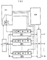
- FIG. 1 schematically shows an ATM network operating according to an asynchronous transfer principle ("asynchronous transfer mode"), which may have a plurality of inputs and a plurality of outputs.
- the inputs and outputs are each designed to receive or deliver message cells having a cell header and an information part with a fixed maximum transmission bit rate.
- a treatment device A is connected to at least a fixed number of inputs E1,... Em, which on the input side is connected to a feeder line ZL stands.
- This feeder line transmits message cells with a higher transmission bit rate than the transmission bit rate defined for the inputs and outputs.
- the number of inputs connected to the treatment device A corresponds to the bit rate ratio of the transmission bit rate defined for the feeder line to the transmission bit rate defined for the inputs and outputs of the ATM network, taking into account additional information to be transmitted within the ATM network to be explained.
- an evaluation device B is connected to at least a fixed number of outputs A1,..., Am, which may be assigned to the aforementioned inputs, and is connected on the output side to a customer line AL.
- This customer line is provided for the transmission of message cells which correspond to the previously mentioned message cells occurring on the feeder line ZL.
- the number of outputs again corresponds to the bit rate ratio of the transmission bit rate defined for the customer line to the transmission bit rate defined for these outputs, taking into account the additional information mentioned.
- the message cells occurring on the feeder line ZL which may be assigned to n different virtual connections, are first inserted into a "first-in-first-out" memory FIFO1 within the treatment device A.
- the message signals contained in message cells of a virtual connection are then divided into signal sections and inserted into newly formed message cells, which are assigned to a fixed virtual connection of the ATM network by a corresponding cell header and in one to be explained below, are distributed to the inputs E1 to Em of the ATM network.
- the number of bits of the signal sections mentioned are defined such that they can each be transmitted plus a defined number of information bits in the information part of a message cell.
- a message cell is shown schematically in FIG. 2.
- Such an example consists of 53 octets, the first five octets in a known manner forming a cell header which contains all the control signals required for the transmission of the respective message cell via the ATM network.
- the information part of the message cell consisting of 48 octets is connected to this cell header.
- m octets form the information bits already mentioned.
- the remaining octets i.e. (m - s) octets
- the remaining octets i.e. (m - s) octets
- the remaining octets on the other hand intended for the transmission of test information SNP for the signal section sequence number and a length identifier LK for octets occupied as useful octets in the information part.
- the (48 - m) octets of the information section are finally intended to accommodate a previously mentioned signal section.
- a separate repackaging device is assigned to each of the n virtual connections on the feeder line ZL.
- the n repackaging devices are labeled SUP1 to SUPn.
- the respective repackaging device receives message cells from the "first-in-first-out" memory FIFO1 in accordance with the order in which the individual message cells are written in, which are first depacketized. From the sequence of those contained in these The aforementioned signal sections are then formed for message signals. These are inserted one after the other in message cells of the respective virtual connection. In this case, a signal section sequence number which changes periodically and continuously from message cell to message cell, test information and a length indicator are entered in the information part of the respective message cell. The counting period for this signal section sequence number is determined in accordance with the maximum runtime of a message cell by the ATM network.
- the output lines of all repackaging devices (SUP1 to SUPn) are jointly fed to a transmission buffer device SPU, which cyclically distributes the message cells occurring on the output lines to the inputs E1 to Em of the ATM network.
- the transmission buffer device SPU transmits so-called empty cells to the possible inputs E1 to Em of the ATM network when transmission pauses occur on the output lines of the repackaging devices.
- the message cells fed to the inputs E1 to Em from the transmission buffer device SPU are transmitted to the outputs A1 to Am shown in FIG. 1 via defined transmission paths within the ATM network.
- the evaluation device B connected to the outputs A1 to Am of the ATM network and shown in FIG. 1 has as interface to these outputs a reception buffer device EPU which contains the different virtual connections supplied via the individual outputs forwards associated message cells to connection-specific repackaging devices.
- a reception buffer device EPU which contains the different virtual connections supplied via the individual outputs forwards associated message cells to connection-specific repackaging devices.
- EUP1 to EUPn corresponds to the repackaging devices.
- the repackaging devices are each connected to the receive buffer device EPU via a connecting line.
- the respective repackaging device depackages the message cells supplied via the associated connecting line and joins the signal sections contained therein to one another in accordance with the signal section sequence numbers.
- message signals are first formed by the respective depacking device, the number of bits of which is fixed in such a way that this corresponds to the number of bits that can be transmitted as useful signals in the information part of a message cell, i.e. that is, the message signals in the example given in FIG. 2 comprise 48 octets.
- the message signals are inserted one after the other into message cells of the respective virtual connection.
- These message cells are then fed to a "first-in-first-out" memory FIFO2, which forwards them to the customer line AL in the order of writing.
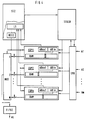
- the treatment device A indicated in FIG. 1 is shown in more detail in FIG. Thereafter, the "first-in-first-out" memory FIFO1 is connected via a control line or a control line bus to a control device ST1, which from this first-in-first-out "memory is the one in the cell header of a message cell currently present at its output contained connection information received Connection information is controlled under the control of a decoder DEC1 of the control device, the repackaging device (SUP1,..., SUPn) in question for the respective virtual connection in order to take over the respective message cell.
- the repackaging devices are connected on the one hand to the "first-in-first-out" memory FIFO1 and on the other hand to the decoder DEC1.
- the repackaging devices SUP1 to SUPn each contain a memory for accommodating message cells.
- four registers are provided in each of these repackaging devices.
- a signal section sequence number that changes continuously from message cell to message cell is entered into a first register, designated SN, by the respective repackaging device.
- a second register is provided for the recording of the associated test information.
- a third register, designated HR, is used to store a fixed cell header that is output by the control device ST1.
- this cell header can be identical to or differ from the cell header used on the feeder line ZL.
- a fourth of the above-mentioned registers which is denoted by LK in FIG. 3, finally serves to accommodate a length identifier already mentioned above.
- the supplied message cells are depacketized by the individual repackaging devices SUP1 to SUPn and the message signals contained therein successively in the associated memory entered.
- the above-mentioned signal sections are formed from these message signals, each of which is preceded by the information stored in the associated four registers in accordance with FIG. 2.
- a length identifier is generally used, which in the example assumed in FIG. 3 corresponds to the 48 m octets of the information part of a message cell.
- the formation of new message cells in the individual repackaging devices SUP1 to SUPn also takes place under the control of a control signal generator GEN, which for this purpose is connected to the repackaging devices via a control line or a control line bus.
- a control signal generator GEN which for this purpose is connected to the repackaging devices via a control line or a control line bus.
- the outputs of the repackaging devices SUP1 to SUPn are connected to inputs of the transmission buffer device SPU which, under the control of the control signal generator GEN, cyclically distributes the message cells supplied to them to the inputs E1 to Em of the ATM network.
- the receive buffer The EPU receives the message cells transmitted via the outputs A1 to Am of the ATM network. After checking the signal section sequence number contained in each of these, the message cells are forwarded to the connection-specific repackaging devices EUP1 to EUPn on the basis of the associated check information in accordance with the connection details contained in the cell headers of these message cells. This can be done, for example, by the reception buffer device EPU transmitting the connection details of the respective message cell to a control signal generator STGEN, which, in accordance with these connection details, transmits the relevant repackaging device via a control line or control bus arrangement common to all repackaging devices for receiving the releases the respective message cell.
- a control signal generator STGEN which, in accordance with these connection details, transmits the relevant repackaging device via a control line or control bus arrangement common to all repackaging devices for receiving the releases the respective message cell.
- the message cells are first unpackaged, the signal sections contained therein being entered in memory locations of a read / write memory RAM associated with the respective repackaging device.
- the associated signal section sequence number which is entered in a write address register AR in the respective repackaging device, is used as the memory address for the respective signal section.
- the length identifiers associated with the signal sections are also entered in the individual memory locations of the read-write memory RAM.
- the respective repackaging device (EUP1 to EUPn) turns the signal sections stored in the associated read / write memory RAM into consecutive ones, taking into account the length indicators stored with them Message signals are formed in the size specified above, which are inserted one after the other in message cells of the respective virtual connection.
- the cell header required for these message cells is stored in the respective repackaging device.
- the start address within the random access memory RAM for the formation of message signals to be inserted into a message cell is recorded in a read address register ARout of the respective repackaging device. This start address is updated every time a message cell is formed.
- the respective repackaging device In the presence of a message cell, which may be temporarily stored in an output register of the respective repackaging device, the respective repackaging device emits a message signal to a reading controller LS of a control device ST2. In response to such a signal, a decoder DEC2 connected to the read control LS controls the respective repackaging device for the delivery of the message cell currently present.
- the outputs of the repackaging devices EUP1 to EUPn are connected to inputs of a multiplexer Mux, which is also controlled by the decoder DEC2 and via which the individual message cells delivered are fed to the "first-in-first-out" memory FIFO2. From here, the message cells are then forwarded to the customer line AL, taking into account the order in which these message cells are written.
Landscapes
- Engineering & Computer Science (AREA)
- Computer Networks & Wireless Communication (AREA)
- Signal Processing (AREA)
- Data Exchanges In Wide-Area Networks (AREA)
Priority Applications (5)
| Application Number | Priority Date | Filing Date | Title |
|---|---|---|---|
| DE59209115T DE59209115D1 (de) | 1992-08-28 | 1992-08-28 | Verfahren und Schaltungsanordnung zum Übertragen von Nachrichtenzellen innerhalb eines ATM-Netzes |
| EP92114798A EP0584398B1 (fr) | 1992-08-28 | 1992-08-28 | Procédé et circuit pour transmettre des cellules d'information dans un réseau ATM |
| AT92114798T ATE162034T1 (de) | 1992-08-28 | 1992-08-28 | Verfahren und schaltungsanordnung zum übertragen von nachrichtenzellen innerhalb eines atm-netzes |
| JP20505393A JPH06177907A (ja) | 1992-08-28 | 1993-08-19 | セル伝送方法及び回路装置 |
| US08/111,000 US5394398A (en) | 1992-08-28 | 1993-08-24 | Method and circuit arrangement for the transmission of message cells within an ATM network |
Applications Claiming Priority (1)
| Application Number | Priority Date | Filing Date | Title |
|---|---|---|---|
| EP92114798A EP0584398B1 (fr) | 1992-08-28 | 1992-08-28 | Procédé et circuit pour transmettre des cellules d'information dans un réseau ATM |
Publications (2)
| Publication Number | Publication Date |
|---|---|
| EP0584398A1 true EP0584398A1 (fr) | 1994-03-02 |
| EP0584398B1 EP0584398B1 (fr) | 1998-01-07 |
Family
ID=8209958
Family Applications (1)
| Application Number | Title | Priority Date | Filing Date |
|---|---|---|---|
| EP92114798A Expired - Lifetime EP0584398B1 (fr) | 1992-08-28 | 1992-08-28 | Procédé et circuit pour transmettre des cellules d'information dans un réseau ATM |
Country Status (5)
| Country | Link |
|---|---|
| US (1) | US5394398A (fr) |
| EP (1) | EP0584398B1 (fr) |
| JP (1) | JPH06177907A (fr) |
| AT (1) | ATE162034T1 (fr) |
| DE (1) | DE59209115D1 (fr) |
Cited By (1)
| Publication number | Priority date | Publication date | Assignee | Title |
|---|---|---|---|---|
| WO1998008355A1 (fr) * | 1996-08-16 | 1998-02-26 | Northern Telecom Limited | Multiplexage inverse des donnees numeriques |
Families Citing this family (39)
| Publication number | Priority date | Publication date | Assignee | Title |
|---|---|---|---|---|
| DE4331579C2 (de) * | 1993-09-16 | 1995-07-06 | Siemens Ag | Verfahren zum Übertragen von Nachrichtenzellen über redundante virtuelle Pfadpaare eines ATM-Kommunikationsnetzes |
| FI98773C (fi) * | 1994-02-28 | 1997-08-11 | Nokia Telecommunications Oy | Menetelmä liikenteen jakamiseksi ATM-tekniikalla toteutetussa tietoliikenneverkossa |
| JP3405800B2 (ja) * | 1994-03-16 | 2003-05-12 | 富士通株式会社 | Atmによる可変長セルの転送方式,atmによる可変長セルのスイッチ及びatmによる可変長セルの交換機 |
| US5920562A (en) * | 1996-11-22 | 1999-07-06 | Sprint Communications Co. L.P. | Systems and methods for providing enhanced services for telecommunication call |
| US5991301A (en) * | 1994-05-05 | 1999-11-23 | Sprint Communications Co. L.P. | Broadband telecommunications system |
| US6633561B2 (en) | 1994-05-05 | 2003-10-14 | Sprint Communications Company, L.P. | Method, system and apparatus for telecommunications control |
| JPH10500542A (ja) | 1994-05-05 | 1998-01-13 | スプリント コミュニケーションズ カンパニー,エル.ピー. | 電気通信制御のための方法、方式(システム)、及び、装置 |
| US6430195B1 (en) | 1994-05-05 | 2002-08-06 | Sprint Communications Company L.P. | Broadband telecommunications system interface |
| US6172977B1 (en) * | 1994-05-05 | 2001-01-09 | Sprint Communications Company, L. P. | ATM direct access line system |
| US5926482A (en) | 1994-05-05 | 1999-07-20 | Sprint Communications Co. L.P. | Telecommunications apparatus, system, and method with an enhanced signal transfer point |
| US6181703B1 (en) * | 1995-09-08 | 2001-01-30 | Sprint Communications Company L. P. | System for managing telecommunications |
| US6314103B1 (en) | 1994-05-05 | 2001-11-06 | Sprint Communications Company, L.P. | System and method for allocating bandwidth for a call |
| US6031840A (en) * | 1995-12-07 | 2000-02-29 | Sprint Communications Co. L.P. | Telecommunications system |
| US6023474A (en) * | 1996-11-22 | 2000-02-08 | Sprint Communications C.O.L.P. | Broadband telecommunications system interface |
| FR2737371A1 (fr) * | 1995-07-26 | 1997-01-31 | Trt Telecom Radio Electr | Securisation par doublement d'au moins certaines voies logiques dans un reseau de telecommunications |
| WO1997028622A1 (fr) * | 1996-02-02 | 1997-08-07 | Sprint Communications Company, L.P. | Systeme de passerelle mta |
| US5870550A (en) * | 1996-02-26 | 1999-02-09 | Network Engineering Software | Web server employing multi-homed, moldular framework |
| US5826014A (en) * | 1996-02-06 | 1998-10-20 | Network Engineering Software | Firewall system for protecting network elements connected to a public network |
| US5898830A (en) * | 1996-10-17 | 1999-04-27 | Network Engineering Software | Firewall providing enhanced network security and user transparency |
| US8117298B1 (en) | 1996-02-26 | 2012-02-14 | Graphon Corporation | Multi-homed web server |
| US6018525A (en) * | 1996-03-11 | 2000-01-25 | Sprint Communications Company, L.P. | ATM transport of voice band signals with channel associated signaling |
| US5940393A (en) * | 1996-05-28 | 1999-08-17 | Sprint Communications Co. L.P. | Telecommunications system with a connection processing system |
| US6014378A (en) * | 1996-11-22 | 2000-01-11 | Sprint Communications Company, L.P. | Telecommunications tandem system for circuit-based traffic |
| CA2271926C (fr) | 1996-11-22 | 2005-10-11 | Sprint Communications Company, L.P. | Systeme et procede de transport d'un appel dans un reseau de telecommunication |
| US6115380A (en) * | 1996-11-22 | 2000-09-05 | Sprint Communications Co., L.P. | Broadband telecommunications system |
| US6002689A (en) * | 1996-11-22 | 1999-12-14 | Sprint Communications Co. L.P. | System and method for interfacing a local communication device |
| US6067299A (en) * | 1997-04-16 | 2000-05-23 | Sprint Communications Company, L.P. | Communications system for providing ATM connections and echo cancellation |
| US6704327B1 (en) | 1997-05-09 | 2004-03-09 | Sprint Communications Company, L.P. | System and method for connecting a call |
| US6137800A (en) * | 1997-05-09 | 2000-10-24 | Sprint Communications Company, L. P. | System and method for connecting a call |
| US6178170B1 (en) | 1997-05-13 | 2001-01-23 | Sprint Communications Company, L. P. | System and method for transporting a call |
| US6781994B1 (en) * | 1997-12-25 | 2004-08-24 | Kabushiki Kaisha Toshiba | Distributing ATM cells to output ports based upon destination information using ATM switch core and IP forwarding |
| US6470019B1 (en) | 1998-02-20 | 2002-10-22 | Sprint Communications Company L.P. | System and method for treating a call for call processing |
| US6483837B1 (en) | 1998-02-20 | 2002-11-19 | Sprint Communications Company L.P. | System and method for connecting a call with an interworking system |
| US6563918B1 (en) | 1998-02-20 | 2003-05-13 | Sprint Communications Company, LP | Telecommunications system architecture for connecting a call |
| US6160871A (en) | 1998-04-10 | 2000-12-12 | Sprint Communications Company, L.P. | Communications test system |
| FI106504B (fi) * | 1998-10-06 | 2001-02-15 | Nokia Networks Oy | Datan segmentointimenetelmä tietoliikennejärjestelmässä |
| US6724765B1 (en) | 1998-12-22 | 2004-04-20 | Sprint Communications Company, L.P. | Telecommunication call processing and connection system architecture |
| US6888833B1 (en) | 1998-12-22 | 2005-05-03 | Sprint Communications Company L.P. | System and method for processing call signaling |
| US7965729B2 (en) * | 2001-05-23 | 2011-06-21 | Polytechnic University | Transferring data such as files |
Citations (3)
| Publication number | Priority date | Publication date | Assignee | Title |
|---|---|---|---|---|
| EP0355797A2 (fr) * | 1988-08-26 | 1990-02-28 | Hitachi, Ltd. | Appareil de signalisation pour utilisation dans un système de commutation ATM |
| EP0471380A1 (fr) * | 1990-08-17 | 1992-02-19 | Hitachi, Ltd. | Commutateur ATM |
| EP0384936B1 (fr) * | 1989-03-03 | 1994-06-15 | Siemens Aktiengesellschaft | Procédé et dispositif pour transmettre des paquets d'information provenant de lignes d'entrée via un dispositif à communication de paquets |
Family Cites Families (4)
| Publication number | Priority date | Publication date | Assignee | Title |
|---|---|---|---|---|
| EP0441787B1 (fr) * | 1989-08-09 | 1994-12-07 | BELL TELEPHONE MANUFACTURING COMPANY Naamloze Vennootschap | Element de commutation de communications servant a la transmission de cellules divisees en sous-cellules |
| JP2907886B2 (ja) * | 1989-09-14 | 1999-06-21 | 株式会社日立製作所 | スイッチングシステム |
| US5204882A (en) * | 1990-12-14 | 1993-04-20 | Bell Communications Research, Inc. | Service clock recovery for variable bit rate services |
| EP0512141A1 (fr) * | 1991-05-07 | 1992-11-11 | Siemens Aktiengesellschaft | Procédé pour commuter un flux de données du type ATM à grand débit dans un réseau de commutation à débit faible |
-
1992
- 1992-08-28 AT AT92114798T patent/ATE162034T1/de not_active IP Right Cessation
- 1992-08-28 DE DE59209115T patent/DE59209115D1/de not_active Expired - Fee Related
- 1992-08-28 EP EP92114798A patent/EP0584398B1/fr not_active Expired - Lifetime
-
1993
- 1993-08-19 JP JP20505393A patent/JPH06177907A/ja not_active Withdrawn
- 1993-08-24 US US08/111,000 patent/US5394398A/en not_active Expired - Fee Related
Patent Citations (3)
| Publication number | Priority date | Publication date | Assignee | Title |
|---|---|---|---|---|
| EP0355797A2 (fr) * | 1988-08-26 | 1990-02-28 | Hitachi, Ltd. | Appareil de signalisation pour utilisation dans un système de commutation ATM |
| EP0384936B1 (fr) * | 1989-03-03 | 1994-06-15 | Siemens Aktiengesellschaft | Procédé et dispositif pour transmettre des paquets d'information provenant de lignes d'entrée via un dispositif à communication de paquets |
| EP0471380A1 (fr) * | 1990-08-17 | 1992-02-19 | Hitachi, Ltd. | Commutateur ATM |
Cited By (5)
| Publication number | Priority date | Publication date | Assignee | Title |
|---|---|---|---|---|
| WO1998008355A1 (fr) * | 1996-08-16 | 1998-02-26 | Northern Telecom Limited | Multiplexage inverse des donnees numeriques |
| US6205142B1 (en) | 1996-08-16 | 2001-03-20 | Nortel Networks Limited | Inverse multiplexing of digital data |
| US6894977B1 (en) | 1996-08-16 | 2005-05-17 | Nortel Networks Limited | Inverse multiplexing of digital data |
| US7570595B2 (en) | 1996-08-16 | 2009-08-04 | Nortel Networks Limited | Inverse multiplexing of digital data |
| US8125912B2 (en) | 1996-08-16 | 2012-02-28 | Ericsson Ab | Inverse multiplexing of digital data |
Also Published As
| Publication number | Publication date |
|---|---|
| DE59209115D1 (de) | 1998-02-12 |
| US5394398A (en) | 1995-02-28 |
| EP0584398B1 (fr) | 1998-01-07 |
| JPH06177907A (ja) | 1994-06-24 |
| ATE162034T1 (de) | 1998-01-15 |
Similar Documents
| Publication | Publication Date | Title |
|---|---|---|
| EP0584398B1 (fr) | Procédé et circuit pour transmettre des cellules d'information dans un réseau ATM | |
| EP0384936B1 (fr) | Procédé et dispositif pour transmettre des paquets d'information provenant de lignes d'entrée via un dispositif à communication de paquets | |
| DE69019081T2 (de) | ATM-Vermittlungssystem mit Doppelvermittlerstruktur. | |
| DE68919856T2 (de) | Nachrichtenvermittlungselement zur übertragung von zellen unterteilt in teilzellen. | |
| EP0453607B1 (fr) | Méthode et dispositif pour réduire la perte de paquets d'information, transmis par un commutateur de paquets | |
| EP0315919B1 (fr) | Noeud de commutation pour la commutation de signaux de données contenus dans des paquets de données | |
| EP0329005B1 (fr) | Procédé pour l'établissement de circuits virtuels à travers les commutateurs d'un dispositif de commutation à plusieurs étages | |
| EP0315918B1 (fr) | Noeud de commutation pour la commutation de signaux de données contenus dans des paquets de données | |
| EP0566961B1 (fr) | Procédé et circuit pour faire respecter le débit de transmission préaccordé dans un dispositif de commutation ATM | |
| EP0512141A1 (fr) | Procédé pour commuter un flux de données du type ATM à grand débit dans un réseau de commutation à débit faible | |
| EP0453606B1 (fr) | Méthode et dispositif pour réduire la perte de paquets d'information, transmis par un commutateur de paquets | |
| EP0576856A2 (fr) | Procédé et circuit pour la transmission d'un flux ATM continu de bits | |
| EP0685950A2 (fr) | Réseau local à mode de transfer asynchrone (ATM) | |
| EP0442581B1 (fr) | Système de communication asynchrone à division temporelle | |
| EP0173274B1 (fr) | Méthode et montage pour la réalisation et la maintenance d'une liaison à division temporelle à large bande | |
| EP0685949A2 (fr) | Système de transmission de paquets | |
| EP0454218B1 (fr) | Système de transmission à division temporelle | |
| EP0443672A2 (fr) | Système à mode de transfert asynchrone | |
| EP0603424A1 (fr) | Procédé et circuit pour transmettre des cellules de communication par un dispositif de communication à ATM | |
| DE3210462A1 (de) | Schaltungsanordnung zur uebertragung von datensignalpaketen zwischen teilnehmerstellen und einer paketvermittlungsstelle | |
| EP0584387B1 (fr) | Procédé et circuit pour surveiller l'agencement de cellules pendant la transmission des cellules d'information | |
| DE69611637T2 (de) | ATM-Koppelfeld | |
| EP0046259B1 (fr) | Procédé pour établir des connections de postes d'abonnés ou lignes de transmission reliés à une centrale de commutation de données à convertisseurs de signaux | |
| EP0446387B1 (fr) | Dispositif d'interconnexion pour la réception et la retransmission de cellules d'information transmises en mode de transfert asynchrone | |
| EP0450725B1 (fr) | Système à multiplexage temporel asynchrone avec un réseau de commutation |
Legal Events
| Date | Code | Title | Description |
|---|---|---|---|
| PUAI | Public reference made under article 153(3) epc to a published international application that has entered the european phase |
Free format text: ORIGINAL CODE: 0009012 |
|
| AK | Designated contracting states |
Kind code of ref document: A1 Designated state(s): AT BE CH DE FR GB IT LI NL SE |
|
| 17P | Request for examination filed |
Effective date: 19940322 |
|
| GRAG | Despatch of communication of intention to grant |
Free format text: ORIGINAL CODE: EPIDOS AGRA |
|
| 17Q | First examination report despatched |
Effective date: 19970327 |
|
| GRAG | Despatch of communication of intention to grant |
Free format text: ORIGINAL CODE: EPIDOS AGRA |
|
| GRAH | Despatch of communication of intention to grant a patent |
Free format text: ORIGINAL CODE: EPIDOS IGRA |
|
| GRAH | Despatch of communication of intention to grant a patent |
Free format text: ORIGINAL CODE: EPIDOS IGRA |
|
| GRAA | (expected) grant |
Free format text: ORIGINAL CODE: 0009210 |
|
| AK | Designated contracting states |
Kind code of ref document: B1 Designated state(s): AT BE CH DE FR GB IT LI NL SE |
|
| REF | Corresponds to: |
Ref document number: 162034 Country of ref document: AT Date of ref document: 19980115 Kind code of ref document: T |
|
| REG | Reference to a national code |
Ref country code: CH Ref legal event code: NV Representative=s name: SIEMENS SCHWEIZ AG Ref country code: CH Ref legal event code: EP |
|
| REF | Corresponds to: |
Ref document number: 59209115 Country of ref document: DE Date of ref document: 19980212 |
|
| ET | Fr: translation filed | ||
| ITF | It: translation for a ep patent filed | ||
| GBT | Gb: translation of ep patent filed (gb section 77(6)(a)/1977) |
Effective date: 19980331 |
|
| PGFP | Annual fee paid to national office [announced via postgrant information from national office to epo] |
Ref country code: GB Payment date: 19980721 Year of fee payment: 7 |
|
| PGFP | Annual fee paid to national office [announced via postgrant information from national office to epo] |
Ref country code: AT Payment date: 19980729 Year of fee payment: 7 |
|
| PGFP | Annual fee paid to national office [announced via postgrant information from national office to epo] |
Ref country code: BE Payment date: 19980818 Year of fee payment: 7 |
|
| PGFP | Annual fee paid to national office [announced via postgrant information from national office to epo] |
Ref country code: SE Payment date: 19980819 Year of fee payment: 7 |
|
| PGFP | Annual fee paid to national office [announced via postgrant information from national office to epo] |
Ref country code: NL Payment date: 19980825 Year of fee payment: 7 |
|
| PGFP | Annual fee paid to national office [announced via postgrant information from national office to epo] |
Ref country code: FR Payment date: 19980826 Year of fee payment: 7 |
|
| PGFP | Annual fee paid to national office [announced via postgrant information from national office to epo] |
Ref country code: DE Payment date: 19981020 Year of fee payment: 7 |
|
| PLBE | No opposition filed within time limit |
Free format text: ORIGINAL CODE: 0009261 |
|
| PGFP | Annual fee paid to national office [announced via postgrant information from national office to epo] |
Ref country code: CH Payment date: 19981116 Year of fee payment: 7 |
|
| 26N | No opposition filed | ||
| PG25 | Lapsed in a contracting state [announced via postgrant information from national office to epo] |
Ref country code: GB Free format text: LAPSE BECAUSE OF NON-PAYMENT OF DUE FEES Effective date: 19990828 Ref country code: AT Free format text: LAPSE BECAUSE OF NON-PAYMENT OF DUE FEES Effective date: 19990828 |
|
| PG25 | Lapsed in a contracting state [announced via postgrant information from national office to epo] |
Ref country code: SE Free format text: THE PATENT HAS BEEN ANNULLED BY A DECISION OF A NATIONAL AUTHORITY Effective date: 19990830 |
|
| PG25 | Lapsed in a contracting state [announced via postgrant information from national office to epo] |
Ref country code: LI Free format text: LAPSE BECAUSE OF NON-PAYMENT OF DUE FEES Effective date: 19990831 Ref country code: CH Free format text: LAPSE BECAUSE OF NON-PAYMENT OF DUE FEES Effective date: 19990831 Ref country code: BE Free format text: LAPSE BECAUSE OF NON-PAYMENT OF DUE FEES Effective date: 19990831 |
|
| BERE | Be: lapsed |
Owner name: SIEMENS A.G. Effective date: 19990831 |
|
| PG25 | Lapsed in a contracting state [announced via postgrant information from national office to epo] |
Ref country code: NL Free format text: LAPSE BECAUSE OF NON-PAYMENT OF DUE FEES Effective date: 20000301 |
|
| REG | Reference to a national code |
Ref country code: CH Ref legal event code: PL |
|
| GBPC | Gb: european patent ceased through non-payment of renewal fee |
Effective date: 19990828 |
|
| PG25 | Lapsed in a contracting state [announced via postgrant information from national office to epo] |
Ref country code: FR Free format text: LAPSE BECAUSE OF NON-PAYMENT OF DUE FEES Effective date: 20000428 |
|
| EUG | Se: european patent has lapsed |
Ref document number: 92114798.9 |
|
| NLV4 | Nl: lapsed or anulled due to non-payment of the annual fee |
Effective date: 20000301 |
|
| PG25 | Lapsed in a contracting state [announced via postgrant information from national office to epo] |
Ref country code: DE Free format text: LAPSE BECAUSE OF NON-PAYMENT OF DUE FEES Effective date: 20000601 |
|
| REG | Reference to a national code |
Ref country code: FR Ref legal event code: ST |
|
| PG25 | Lapsed in a contracting state [announced via postgrant information from national office to epo] |
Ref country code: IT Free format text: LAPSE BECAUSE OF NON-PAYMENT OF DUE FEES;WARNING: LAPSES OF ITALIAN PATENTS WITH EFFECTIVE DATE BEFORE 2007 MAY HAVE OCCURRED AT ANY TIME BEFORE 2007. THE CORRECT EFFECTIVE DATE MAY BE DIFFERENT FROM THE ONE RECORDED. Effective date: 20050828 |