EP0584467B1 - Verfahren zur kontinuierlichen Herstellung eines langgestreckten Hohlprofils aus thermoplastischem Kunststoff - Google Patents
Verfahren zur kontinuierlichen Herstellung eines langgestreckten Hohlprofils aus thermoplastischem Kunststoff Download PDFInfo
- Publication number
- EP0584467B1 EP0584467B1 EP93108723A EP93108723A EP0584467B1 EP 0584467 B1 EP0584467 B1 EP 0584467B1 EP 93108723 A EP93108723 A EP 93108723A EP 93108723 A EP93108723 A EP 93108723A EP 0584467 B1 EP0584467 B1 EP 0584467B1
- Authority
- EP
- European Patent Office
- Prior art keywords
- profiles
- hollow profile
- profile
- partial
- joint zones
- Prior art date
- Legal status (The legal status is an assumption and is not a legal conclusion. Google has not performed a legal analysis and makes no representation as to the accuracy of the status listed.)
- Expired - Lifetime
Links
Images

Classifications
-
- B—PERFORMING OPERATIONS; TRANSPORTING
- B29—WORKING OF PLASTICS; WORKING OF SUBSTANCES IN A PLASTIC STATE IN GENERAL
- B29C—SHAPING OR JOINING OF PLASTICS; SHAPING OF MATERIAL IN A PLASTIC STATE, NOT OTHERWISE PROVIDED FOR; AFTER-TREATMENT OF THE SHAPED PRODUCTS, e.g. REPAIRING
- B29C65/00—Joining or sealing of preformed parts, e.g. welding of plastics materials; Apparatus therefor
- B29C65/56—Joining or sealing of preformed parts, e.g. welding of plastics materials; Apparatus therefor using mechanical means or mechanical connections, e.g. form-fits
-
- B—PERFORMING OPERATIONS; TRANSPORTING
- B29—WORKING OF PLASTICS; WORKING OF SUBSTANCES IN A PLASTIC STATE IN GENERAL
- B29C—SHAPING OR JOINING OF PLASTICS; SHAPING OF MATERIAL IN A PLASTIC STATE, NOT OTHERWISE PROVIDED FOR; AFTER-TREATMENT OF THE SHAPED PRODUCTS, e.g. REPAIRING
- B29C48/00—Extrusion moulding, i.e. expressing the moulding material through a die or nozzle which imparts the desired form; Apparatus therefor
- B29C48/03—Extrusion moulding, i.e. expressing the moulding material through a die or nozzle which imparts the desired form; Apparatus therefor characterised by the shape of the extruded material at extrusion
- B29C48/09—Articles with cross-sections having partially or fully enclosed cavities, e.g. pipes or channels
-
- B—PERFORMING OPERATIONS; TRANSPORTING
- B29—WORKING OF PLASTICS; WORKING OF SUBSTANCES IN A PLASTIC STATE IN GENERAL
- B29C—SHAPING OR JOINING OF PLASTICS; SHAPING OF MATERIAL IN A PLASTIC STATE, NOT OTHERWISE PROVIDED FOR; AFTER-TREATMENT OF THE SHAPED PRODUCTS, e.g. REPAIRING
- B29C48/00—Extrusion moulding, i.e. expressing the moulding material through a die or nozzle which imparts the desired form; Apparatus therefor
- B29C48/03—Extrusion moulding, i.e. expressing the moulding material through a die or nozzle which imparts the desired form; Apparatus therefor characterised by the shape of the extruded material at extrusion
- B29C48/12—Articles with an irregular circumference when viewed in cross-section, e.g. window profiles
-
- B—PERFORMING OPERATIONS; TRANSPORTING
- B29—WORKING OF PLASTICS; WORKING OF SUBSTANCES IN A PLASTIC STATE IN GENERAL
- B29C—SHAPING OR JOINING OF PLASTICS; SHAPING OF MATERIAL IN A PLASTIC STATE, NOT OTHERWISE PROVIDED FOR; AFTER-TREATMENT OF THE SHAPED PRODUCTS, e.g. REPAIRING
- B29C48/00—Extrusion moulding, i.e. expressing the moulding material through a die or nozzle which imparts the desired form; Apparatus therefor
- B29C48/16—Articles comprising two or more components, e.g. co-extruded layers
-
- B—PERFORMING OPERATIONS; TRANSPORTING
- B29—WORKING OF PLASTICS; WORKING OF SUBSTANCES IN A PLASTIC STATE IN GENERAL
- B29C—SHAPING OR JOINING OF PLASTICS; SHAPING OF MATERIAL IN A PLASTIC STATE, NOT OTHERWISE PROVIDED FOR; AFTER-TREATMENT OF THE SHAPED PRODUCTS, e.g. REPAIRING
- B29C48/00—Extrusion moulding, i.e. expressing the moulding material through a die or nozzle which imparts the desired form; Apparatus therefor
- B29C48/25—Component parts, details or accessories; Auxiliary operations
- B29C48/30—Extrusion nozzles or dies
- B29C48/304—Extrusion nozzles or dies specially adapted for bringing together components, e.g. melts within the die
-
- B—PERFORMING OPERATIONS; TRANSPORTING
- B29—WORKING OF PLASTICS; WORKING OF SUBSTANCES IN A PLASTIC STATE IN GENERAL
- B29C—SHAPING OR JOINING OF PLASTICS; SHAPING OF MATERIAL IN A PLASTIC STATE, NOT OTHERWISE PROVIDED FOR; AFTER-TREATMENT OF THE SHAPED PRODUCTS, e.g. REPAIRING
- B29C65/00—Joining or sealing of preformed parts, e.g. welding of plastics materials; Apparatus therefor
-
- B—PERFORMING OPERATIONS; TRANSPORTING
- B29—WORKING OF PLASTICS; WORKING OF SUBSTANCES IN A PLASTIC STATE IN GENERAL
- B29C—SHAPING OR JOINING OF PLASTICS; SHAPING OF MATERIAL IN A PLASTIC STATE, NOT OTHERWISE PROVIDED FOR; AFTER-TREATMENT OF THE SHAPED PRODUCTS, e.g. REPAIRING
- B29C65/00—Joining or sealing of preformed parts, e.g. welding of plastics materials; Apparatus therefor
- B29C65/02—Joining or sealing of preformed parts, e.g. welding of plastics materials; Apparatus therefor by heating, with or without pressure
- B29C65/022—Particular heating or welding methods not otherwise provided for
- B29C65/028—Particular heating or welding methods not otherwise provided for making use of inherent heat, i.e. the heat for the joining comes from the moulding process of one of the parts to be joined
-
- B—PERFORMING OPERATIONS; TRANSPORTING
- B29—WORKING OF PLASTICS; WORKING OF SUBSTANCES IN A PLASTIC STATE IN GENERAL
- B29C—SHAPING OR JOINING OF PLASTICS; SHAPING OF MATERIAL IN A PLASTIC STATE, NOT OTHERWISE PROVIDED FOR; AFTER-TREATMENT OF THE SHAPED PRODUCTS, e.g. REPAIRING
- B29C66/00—General aspects of processes or apparatus for joining preformed parts
- B29C66/01—General aspects dealing with the joint area or with the area to be joined
- B29C66/05—Particular design of joint configurations
- B29C66/10—Particular design of joint configurations particular design of the joint cross-sections
- B29C66/11—Joint cross-sections comprising a single joint-segment, i.e. one of the parts to be joined comprising a single joint-segment in the joint cross-section
- B29C66/112—Single lapped joints
- B29C66/1122—Single lap to lap joints, i.e. overlap joints
-
- B—PERFORMING OPERATIONS; TRANSPORTING
- B29—WORKING OF PLASTICS; WORKING OF SUBSTANCES IN A PLASTIC STATE IN GENERAL
- B29C—SHAPING OR JOINING OF PLASTICS; SHAPING OF MATERIAL IN A PLASTIC STATE, NOT OTHERWISE PROVIDED FOR; AFTER-TREATMENT OF THE SHAPED PRODUCTS, e.g. REPAIRING
- B29C66/00—General aspects of processes or apparatus for joining preformed parts
- B29C66/50—General aspects of joining tubular articles; General aspects of joining long products, i.e. bars or profiled elements; General aspects of joining single elements to tubular articles, hollow articles or bars; General aspects of joining several hollow-preforms to form hollow or tubular articles
- B29C66/51—Joining tubular articles, profiled elements or bars; Joining single elements to tubular articles, hollow articles or bars; Joining several hollow-preforms to form hollow or tubular articles
- B29C66/54—Joining several hollow-preforms, e.g. half-shells, to form hollow articles, e.g. for making balls, containers; Joining several hollow-preforms, e.g. half-cylinders, to form tubular articles
- B29C66/547—Joining several hollow-preforms, e.g. half-cylinders, to form tubular articles, e.g. endless tubes
-
- B—PERFORMING OPERATIONS; TRANSPORTING
- B29—WORKING OF PLASTICS; WORKING OF SUBSTANCES IN A PLASTIC STATE IN GENERAL
- B29C—SHAPING OR JOINING OF PLASTICS; SHAPING OF MATERIAL IN A PLASTIC STATE, NOT OTHERWISE PROVIDED FOR; AFTER-TREATMENT OF THE SHAPED PRODUCTS, e.g. REPAIRING
- B29C66/00—General aspects of processes or apparatus for joining preformed parts
- B29C66/70—General aspects of processes or apparatus for joining preformed parts characterised by the composition, physical properties or the structure of the material of the parts to be joined; Joining with non-plastics material
- B29C66/73—General aspects of processes or apparatus for joining preformed parts characterised by the composition, physical properties or the structure of the material of the parts to be joined; Joining with non-plastics material characterised by the intensive physical properties of the material of the parts to be joined, by the optical properties of the material of the parts to be joined, by the extensive physical properties of the parts to be joined, by the state of the material of the parts to be joined or by the material of the parts to be joined being a thermoplastic or a thermoset
- B29C66/739—General aspects of processes or apparatus for joining preformed parts characterised by the composition, physical properties or the structure of the material of the parts to be joined; Joining with non-plastics material characterised by the intensive physical properties of the material of the parts to be joined, by the optical properties of the material of the parts to be joined, by the extensive physical properties of the parts to be joined, by the state of the material of the parts to be joined or by the material of the parts to be joined being a thermoplastic or a thermoset characterised by the material of the parts to be joined being a thermoplastic or a thermoset
- B29C66/7392—General aspects of processes or apparatus for joining preformed parts characterised by the composition, physical properties or the structure of the material of the parts to be joined; Joining with non-plastics material characterised by the intensive physical properties of the material of the parts to be joined, by the optical properties of the material of the parts to be joined, by the extensive physical properties of the parts to be joined, by the state of the material of the parts to be joined or by the material of the parts to be joined being a thermoplastic or a thermoset characterised by the material of the parts to be joined being a thermoplastic or a thermoset characterised by the material of at least one of the parts being a thermoplastic
- B29C66/73921—General aspects of processes or apparatus for joining preformed parts characterised by the composition, physical properties or the structure of the material of the parts to be joined; Joining with non-plastics material characterised by the intensive physical properties of the material of the parts to be joined, by the optical properties of the material of the parts to be joined, by the extensive physical properties of the parts to be joined, by the state of the material of the parts to be joined or by the material of the parts to be joined being a thermoplastic or a thermoset characterised by the material of the parts to be joined being a thermoplastic or a thermoset characterised by the material of at least one of the parts being a thermoplastic characterised by the materials of both parts being thermoplastics
-
- B—PERFORMING OPERATIONS; TRANSPORTING
- B29—WORKING OF PLASTICS; WORKING OF SUBSTANCES IN A PLASTIC STATE IN GENERAL
- B29C—SHAPING OR JOINING OF PLASTICS; SHAPING OF MATERIAL IN A PLASTIC STATE, NOT OTHERWISE PROVIDED FOR; AFTER-TREATMENT OF THE SHAPED PRODUCTS, e.g. REPAIRING
- B29C66/00—General aspects of processes or apparatus for joining preformed parts
- B29C66/80—General aspects of machine operations or constructions and parts thereof
- B29C66/83—General aspects of machine operations or constructions and parts thereof characterised by the movement of the joining or pressing tools
- B29C66/836—Moving relative to and tangentially to the parts to be joined, e.g. transversely to the displacement of the parts to be joined, e.g. using a X-Y table
-
- B—PERFORMING OPERATIONS; TRANSPORTING
- B29—WORKING OF PLASTICS; WORKING OF SUBSTANCES IN A PLASTIC STATE IN GENERAL
- B29C—SHAPING OR JOINING OF PLASTICS; SHAPING OF MATERIAL IN A PLASTIC STATE, NOT OTHERWISE PROVIDED FOR; AFTER-TREATMENT OF THE SHAPED PRODUCTS, e.g. REPAIRING
- B29C2791/00—Shaping characteristics in general
- B29C2791/003—Making articles of indefinite length
-
- B—PERFORMING OPERATIONS; TRANSPORTING
- B29—WORKING OF PLASTICS; WORKING OF SUBSTANCES IN A PLASTIC STATE IN GENERAL
- B29C—SHAPING OR JOINING OF PLASTICS; SHAPING OF MATERIAL IN A PLASTIC STATE, NOT OTHERWISE PROVIDED FOR; AFTER-TREATMENT OF THE SHAPED PRODUCTS, e.g. REPAIRING
- B29C48/00—Extrusion moulding, i.e. expressing the moulding material through a die or nozzle which imparts the desired form; Apparatus therefor
-
- B—PERFORMING OPERATIONS; TRANSPORTING
- B29—WORKING OF PLASTICS; WORKING OF SUBSTANCES IN A PLASTIC STATE IN GENERAL
- B29C—SHAPING OR JOINING OF PLASTICS; SHAPING OF MATERIAL IN A PLASTIC STATE, NOT OTHERWISE PROVIDED FOR; AFTER-TREATMENT OF THE SHAPED PRODUCTS, e.g. REPAIRING
- B29C48/00—Extrusion moulding, i.e. expressing the moulding material through a die or nozzle which imparts the desired form; Apparatus therefor
- B29C48/001—Combinations of extrusion moulding with other shaping operations
-
- B—PERFORMING OPERATIONS; TRANSPORTING
- B29—WORKING OF PLASTICS; WORKING OF SUBSTANCES IN A PLASTIC STATE IN GENERAL
- B29C—SHAPING OR JOINING OF PLASTICS; SHAPING OF MATERIAL IN A PLASTIC STATE, NOT OTHERWISE PROVIDED FOR; AFTER-TREATMENT OF THE SHAPED PRODUCTS, e.g. REPAIRING
- B29C48/00—Extrusion moulding, i.e. expressing the moulding material through a die or nozzle which imparts the desired form; Apparatus therefor
- B29C48/001—Combinations of extrusion moulding with other shaping operations
- B29C48/0011—Combinations of extrusion moulding with other shaping operations combined with compression moulding
-
- B—PERFORMING OPERATIONS; TRANSPORTING
- B29—WORKING OF PLASTICS; WORKING OF SUBSTANCES IN A PLASTIC STATE IN GENERAL
- B29C—SHAPING OR JOINING OF PLASTICS; SHAPING OF MATERIAL IN A PLASTIC STATE, NOT OTHERWISE PROVIDED FOR; AFTER-TREATMENT OF THE SHAPED PRODUCTS, e.g. REPAIRING
- B29C48/00—Extrusion moulding, i.e. expressing the moulding material through a die or nozzle which imparts the desired form; Apparatus therefor
- B29C48/001—Combinations of extrusion moulding with other shaping operations
- B29C48/0022—Combinations of extrusion moulding with other shaping operations combined with cutting
-
- B—PERFORMING OPERATIONS; TRANSPORTING
- B29—WORKING OF PLASTICS; WORKING OF SUBSTANCES IN A PLASTIC STATE IN GENERAL
- B29C—SHAPING OR JOINING OF PLASTICS; SHAPING OF MATERIAL IN A PLASTIC STATE, NOT OTHERWISE PROVIDED FOR; AFTER-TREATMENT OF THE SHAPED PRODUCTS, e.g. REPAIRING
- B29C48/00—Extrusion moulding, i.e. expressing the moulding material through a die or nozzle which imparts the desired form; Apparatus therefor
- B29C48/15—Extrusion moulding, i.e. expressing the moulding material through a die or nozzle which imparts the desired form; Apparatus therefor incorporating preformed parts or layers, e.g. extrusion moulding around inserts
-
- B—PERFORMING OPERATIONS; TRANSPORTING
- B29—WORKING OF PLASTICS; WORKING OF SUBSTANCES IN A PLASTIC STATE IN GENERAL
- B29C—SHAPING OR JOINING OF PLASTICS; SHAPING OF MATERIAL IN A PLASTIC STATE, NOT OTHERWISE PROVIDED FOR; AFTER-TREATMENT OF THE SHAPED PRODUCTS, e.g. REPAIRING
- B29C65/00—Joining or sealing of preformed parts, e.g. welding of plastics materials; Apparatus therefor
- B29C65/48—Joining or sealing of preformed parts, e.g. welding of plastics materials; Apparatus therefor using adhesives, i.e. using supplementary joining material; solvent bonding
-
- B—PERFORMING OPERATIONS; TRANSPORTING
- B29—WORKING OF PLASTICS; WORKING OF SUBSTANCES IN A PLASTIC STATE IN GENERAL
- B29C—SHAPING OR JOINING OF PLASTICS; SHAPING OF MATERIAL IN A PLASTIC STATE, NOT OTHERWISE PROVIDED FOR; AFTER-TREATMENT OF THE SHAPED PRODUCTS, e.g. REPAIRING
- B29C66/00—General aspects of processes or apparatus for joining preformed parts
- B29C66/70—General aspects of processes or apparatus for joining preformed parts characterised by the composition, physical properties or the structure of the material of the parts to be joined; Joining with non-plastics material
- B29C66/71—General aspects of processes or apparatus for joining preformed parts characterised by the composition, physical properties or the structure of the material of the parts to be joined; Joining with non-plastics material characterised by the composition of the plastics material of the parts to be joined
-
- B—PERFORMING OPERATIONS; TRANSPORTING
- B29—WORKING OF PLASTICS; WORKING OF SUBSTANCES IN A PLASTIC STATE IN GENERAL
- B29C—SHAPING OR JOINING OF PLASTICS; SHAPING OF MATERIAL IN A PLASTIC STATE, NOT OTHERWISE PROVIDED FOR; AFTER-TREATMENT OF THE SHAPED PRODUCTS, e.g. REPAIRING
- B29C66/00—General aspects of processes or apparatus for joining preformed parts
- B29C66/70—General aspects of processes or apparatus for joining preformed parts characterised by the composition, physical properties or the structure of the material of the parts to be joined; Joining with non-plastics material
- B29C66/72—General aspects of processes or apparatus for joining preformed parts characterised by the composition, physical properties or the structure of the material of the parts to be joined; Joining with non-plastics material characterised by the structure of the material of the parts to be joined
- B29C66/721—Fibre-reinforced materials
- B29C66/7212—Fibre-reinforced materials characterised by the composition of the fibres
-
- B—PERFORMING OPERATIONS; TRANSPORTING
- B29—WORKING OF PLASTICS; WORKING OF SUBSTANCES IN A PLASTIC STATE IN GENERAL
- B29L—INDEXING SCHEME ASSOCIATED WITH SUBCLASS B29C, RELATING TO PARTICULAR ARTICLES
- B29L2031/00—Other particular articles
- B29L2031/001—Profiled members, e.g. beams, sections
- B29L2031/003—Profiled members, e.g. beams, sections having a profiled transverse cross-section
Definitions
- the invention relates to a method for producing an elongated hollow profile made of thermoplastic material with a constant hollow profile cross section over the length of the hollow profile.
- hollow profiles are known in various embodiments and for a wide variety of uses. In general, it can be said that the usual elongated hollow profiles made of thermoplastic are molded in one piece and seamlessly. They are extruded accordingly, either by means of free extrusion or by means of a cooling and calibration device connected downstream of the shaping, uncooled or slightly cooled tool.
- the hollow profiles have a complex cross-section, as is the case with window profiles, for example, the known measures are complex and the quality of the products is open to criticism. This applies in particular if the walls and webs of such a hollow profile have different wall thicknesses and strict requirements are made of the tolerances to be observed. One often observes shrinkage-induced sink marks in the profile cross-section. the like
- the invention is based on the technical problem of specifying a method with which an elongated hollow profile made of thermoplastic material, which can be produced very precisely and with close tolerances with respect to the external dimensions, but also with regard to the internal dimensions and the profile chambers so that the hollow profile runs with absolutely small tolerances completely straight or with a given curvature and / or with a given torsion around the hollow profile axis.
- both the quality of the outer surface and the inner surface should meet high requirements.
- the hollow profile can be composed of partial profiles of different or the same partial profile cross-section, even and in particular of partial profiles with greatly different wall thicknesses and different wall thicknesses in the partial profiles. Practically all profile cross sections common in today's application technology can be produced in this way.
- the hollow profiles can consist of partial profiles be assembled from the same plastic.
- the same plastic means plastics of the same material composition with the same or different filling and / or reinforcement.
- the hollow profiles are made of partial profiles by the material composition and / or coloring and / or the filling and / or the reinforcement, for. B. a glass fiber reinforcement composed of different plastic.
- the prepreg tapes consist of glass fibers and. Like. And epoxy resin systems in a special polymerization state.
- the situation is similar in another known method (JP-A-56 115 237), in which the partial cross sections are extruded with longitudinal positive locking elements, cooled and combined in a special device with the locking of the shaped elements.
- the cooling nozzle extrusion process is known per se (cf. Michaeli "extrusion tools for plastics and rubber" Hanser-Verlag 1991, pp. 342 to 345). Put in a simple formula, this cooling nozzle extrusion process is characterized in that the shaping nozzles which define the inner wall and the outer wall of the hollow profiles are cooled. This initially causes intensive cooling of the areas of the plastic strand that come into contact with the cooled tool walls. A sufficiently stable shell is created, as it were. The still flowable plastic is pressed inside the shell. In this way it is achieved that the partial profiles produced by the cooling nozzle extrusion leave the tool with very little tolerance and with a high surface quality. Downstream cooling or calibration measures are not necessary.
- thermoplastics Practically all known thermoplastics can be filled or filled with reinforcement in the form of long or short fibers, for example glass fibers and the like. Like., Set so that they are extruded very low tolerance within the scope of the cooling nozzle extrusion process.
- the invention is based on the knowledge that the specified tolerances can be adhered to very precisely in the cooling nozzle extrusion. It is part of the prior art to connect the partial profiles to one another in a non-displaceable manner according to all spatial coordinates (cf. DE-A-40 36 245), but it has not hitherto been recognized that special measures are necessary and possible when joining to ensure that the hollow profile runs completely straight or according to design specifications with a defined radius of curvature or torsion.
- the invention has recognized that this can be achieved by the tuning rule, which consists in coordinating the length of the individual partial profiles with one another before the union to form the elongated hollow profile in such a way that the elongated hollow profile is straight or with a predetermined curvature and / or with a predetermined torsion about it Hollow profile longitudinal axis runs.
- the sub-profiles are part of the joining measures to be carried out can be supplied accordingly, but can also be deformed and combined accordingly. If a partial profile is longer than the partial profile assigned, for example, on the opposite side, a curvature away from this longer partial profile is achieved.
- a predetermined torsion can be achieved by superposition of the measures described.
- the tolerance limit already stated above can be fallen below in the method according to the invention.
- the partial profiles can, for. B. with partial profile cross-section tolerances in relation to all lengths of the partial profile cross-sections, which, given in millimeters, are less than plus / minus (0.15% plus / minus 0.02 mm).
- the joining areas can be set up in various ways.
- the joining areas are designed as extruded joining areas. It goes without saying that not only are the partial profiles manufactured with low tolerance, but also the partial profiles are joined with low tolerance. This can be easily achieved with the tools of modern joining technology, for example by heating only extremely thin surface layers of the joining areas and integrally connecting them, or by working with an extremely thin adhesive that is applied to the joining areas.
- the partial profiles in the joining areas can be connected to one another in a materially integral manner. It is possible to connect the partial profiles in the joining areas with a positive fit and also with a material fit. On the other hand, the partial profiles in the joining areas can also be adhesively bonded to one another. In this respect, it is within the scope of the invention that the partial profiles in the joining areas are connected to one another in a form-fitting and additionally adhesive manner.
- the partial profiles in the joining areas can also be mechanically connected to one another, namely with the aid of mechanical joining elements, such as, for. B. rivets, pins, clips and clips, or by mechanical joining measures such. B. embossing, hallmarks. It is also within the scope of the invention to connect the partial profiles in the joining areas in a form-fitting and additionally mechanically manner. Otherwise, the joining measures described above can also be combined.
- the plastic for the individual partial profiles can be thermoplasticized in a single extruder and fed to different cooling nozzles.
- thermoplasticize the plastic for the individual partial profiles in separate extruders and to supply cooling nozzles assigned to the extruders.
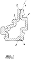
- the hollow profiles 1 shown in FIGS. 1 to 5 consist of thermoplastic. These are elongated hollow profiles 1 of a given length.
- the hollow profile cross section is identical over the entire length of the hollow profile.
- the hollow profiles 1 consist of two partial profiles 2, 3 which have a constant partial profile cross section over the hollow profile length and mutually associated and complementary joining regions 4, 5.
- the partial profiles 2, 3 consist of a special material, namely a plastic that can be extruded with low tolerances using the cooling nozzle extrusion process.
- the lack of tolerance results from the chemical structure of the plastic and / or from the fact that the plastic is provided with fillers or reinforcements in the form of glass fibers or the like.
- 6 and 7 which are explained further below, it can be seen that the partial profiles 2, 3 have been produced by cooling die extrusion. This is possible with tolerances that are extremely small. For reasons of scale, it cannot be seen in the drawing that the tolerances are as small as claimed in claim 1.
- the sub-profiles 2, 3 are connected to one another after the cooling nozzle extrusion with the aid of the joining areas 4, 5 in the longitudinal direction of the hollow profile and in accordance with the two other spatial coordinates. 1 to 5 explain that in the hollow section 1 there is a special vote.
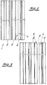
- the length of the individual partial profiles 2, 3 before the union to form the elongated hollow profile 1 is in fact coordinated with one another in such a way that the elongated hollow profile 1 runs straight or with a predefinable curvature. With regard to the coordination with a straight course, reference is made to FIG. 3. Here you can see a gap 6 between the two partial profiles 2, 3, because in FIG. 3 the partial profiles 2, 3 have not yet been joined and are connected to one another.
- FIG. 4 a plan view of the two partial profiles 2, 3, which are not combined with one another and are arranged with a gap 6. It can be seen that the partial profile 2, ie the right one , is considerably longer than the partial profile 3 on the left.
- the joining of the two partial profiles 2, 3 leads to a hollow profile 1 with a desired curvature resulting from the difference in length. If you change the length differences over the circumference of the hollow profile 1, a defined torsion can also be achieved. It goes without saying that the curvature can also be set up according to all three spatial coordinates.
- the cross-sectional representation in FIG. 1 makes it clear that the individual partial profiles 2, 3 have different partial profile cross sections. Otherwise, very different wall thicknesses are realized in the partial profiles 2, 3.
- the partial profiles 2, 3 may consist of the same plastic, but they can also be constructed from different plastics. You can fillers, reinforcements in the form of glass fibers and. Like. Provided.
- the partial profiles 2, 3 can also consist of different materials, the differences being given in terms of material and / or color, or else the partial profiles 2, 3 have different fillings or reinforcements.
- the joining areas 4, 5 are extrusion-joining areas because the partial profiles 2, 3 have been produced by extrusion.
- the partial profiles 2, 3 may in the exemplary embodiment be integrally connected to one another in the manner already described. But one could also realize the joining areas 4, 5 in such a way that a positive connection is set up transversely to the longitudinal direction and additionally bring about a material connection or an adhesive connection. It was not shown in the drawing that the partial profiles 2, 3 can also be mechanically connected to one another, namely by rivets, pins, clamps, clips, by embossing or punching. The measures described can also be combined.
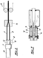
- an extruder 10 for the thermoplasticization of thermoplastic which has a tool head 11 and in the tool head 11 has a shaping tool with cooling nozzles 12.
- the cooling takes place, for example, by water, for which purpose reference is made to FIG. 7.
- the shaping nozzle walls 13 and the flow channels 14 for the cooling water can be seen here.
- a withdrawal device 15 is connected at some distance. In between there is a joining device 16 or joining machine.
- the hollow profile 1, which can be produced on the system shown, is composed of at least two partial profiles 2, 3. These may be partial profiles 2, 3, as have been shown in FIGS. 1 to 5.
- the partial profiles 2, 3 have a constant partial profile cross section. They have mutually associated and mutually complementary joining areas 4, 5.
- a plastic which can be extruded with low tolerances by the cooling nozzle extrusion process is used.
- the partial profiles 2, 3 are manufactured with very little tolerance using the cooling nozzle extrusion process.
- the cooling nozzle extrusion process is carried out in such a way that the partial profile cross sections have partial profile cross section tolerances which are below the specified upper limit. It can be seen in FIG.
- FIGS. 2 and 3 or 4 and 5 With regard to the measure that the length of the individual sub-profiles 2, 3 is adjusted by influencing the extrusion speed for the individual sub-profiles 2, 3 in the cooling chamber extrusion, reference is made to FIGS. 2 and 3 or 4 and 5. It can be seen that both extremely straight hollow profiles 1 and curved hollow profiles 1 can be produced. This also applies to twisted hollow profiles 1, but this has not been drawn.
- the plastic for the individual partial profiles 2, 3 is thermoplasticized in a single extruder 10 and fed to the different cooling nozzles 12.
- two extruders could also be set up for thermoplasticizing different plastics.
Landscapes
- Engineering & Computer Science (AREA)
- Mechanical Engineering (AREA)
- Manufacturing & Machinery (AREA)
- Extrusion Moulding Of Plastics Or The Like (AREA)
Description
- Die Erfindung betrifft ein Verfahren zur Herstellung eines langgestreckten Hohlprofils aus thermoplastischem Kunststoff mit über die Hohlprofillänge konstantem Hohlprofilquerschnitt. Derartige Hohlprofile sind in verschiedenen Ausführungsformen und für die verschiedensten Verwendungszwecke bekannt. Allgemein ist zu sagen, daß die üblichen langgestreckten Hohlprofile aus thermoplastischem Kunststoff einteilig und nahtlos ausgeformt werden. Sie werden entsprechend extrudiert, sei es im Wege der freien Extrusion, sei es mit Hilfe einer dem formgebenden, ungekühlten oder wenig gekühlten Werkzeug nachgeschalteten Kühl- und Kalibriereinrichtung. Haben die Hohlprofile einen komplexen Querschnitt, wie es beispielsweise bei Fensterprofilen der Fall ist, so sind die bekannten Maßnahmen aufwendig und die Qualität der Produkte ist der Kritik offen. Das gilt insbesondere, wenn die Wände und Stege eines solchen Hohlprofils unterschiedliche Wanddicken aufweisen und an die einzuhaltenden Toleranzen strenge Anforderungen gestellt werden. Man beobachtet im Profilquerschnitt häufig schrumpfungsbedingte Einfallsstellen u. dgl.
- Allerdings ist es bekannt (DE-A-40 36 245), ein Kunststoffhohlprofil aus zwei Teilprofilen, nämlich aus zwei identischen Teilprofilen, zusammenzusetzen, wobei die Teilprofile formschlüssig und darüber hinaus im Bereich einer Stoßnaht durch Schweißen vereinigt sind. Die Teilprofile können auf beliebige Art und Weise hergestellt werden. Sie können gerade verlaufen oder auch gebogen sein, jedoch müssen insoweit erhebliche Toleranzen in Kauf genommen werden. Eine Anweisung, wie erreichbar ist, daß das langgestreckte Hohlprofil mit engen Toleranzen gerade oder mit vorgegebener Krümmung und/oder mit vorgegebener Torsion um die Hohlprofilachse verläuft, wird nicht gegeben. Die Praxis zeigt, daß im Rahmen der bekannten Verfahrensweise das langgestreckte Hohlprofil bei der Herstellung unkontrolliert verläuft und nach der Vereinigung der Teilprofile nachgerichtet werden muß. Auch die Oberflächenqualität, insbesondere die der Innenoberfläche, ist der Kritik offen. Im übrigen ist es bekannt, auf ein extrudiertes Hohlprofil aus thermoplastischem Kunststoff ein anderes Profil oder Profilleisten mit anderen physikalischen Eigenschaften aufzuschweißen (DE-U-90 90 014). Auch hier werden in werkstoffmäßiger Hinsicht und bezüglich der Herstellung der Hohlprofile keine besonderen Angaben gemacht, es wird nicht angegeben, wie zu verfahren ist, damit die Hohlprofile gerade oder mit vorgegebener Krümmung und/oder mit vorgegebener Torsion um die Hohlprofillängsachse verlaufen.
- Der Erfindung liegt das technische Problem zugrunde, ein Verfahren anzugeben, mit dem ein langgestrecktes Hohlprofil aus thermoplastischem Kunststoff, welches in bezug auf die Außenmaße, aber auch in bezug auf die Innenmaße und die Profilkammern sehr genau und mit engen Toleranzen hergestellt werden kann, und zwar so, daß das Hohlprofil mit extrem geringen Toleranzen vollkommen gerade oder mit vorgegebener Krümmung und/oder mit vorgegebener Torsion um die Hohlprofilachse verläuft. Darüber hinaus soll sowohl die Qualität der Außenoberfläche als auch die der Innenoberfläche hohen Anforderungen genügen.
- Zur Lösung dieses technischen Problems ist Gegenstand der Erfindung ein Verfahren zur kontinuierlichen Herstellung eines langgestreckten Hohlprofiles aus thermoplastischem Kunststoff mit über die Hohlprofillänge konstantem Hohlprofilquerschnitt:
- a) das Hohlprofil wird aus zumindest zwei Teilprofilen, die über die Hohlprofillänge konstanten Teilprofilquerschnitt sowie einander zugeordnete und zueinander komplementäre Fügebereiche aufweisen, zusammengesetzt,
- b) für die Herstellung der Teilprofile wird ein nach dem Kühldüsenextrusionsverfahren toleranzarm extrudierbarer Kunststoff verwendet,
- c) das Kühldüsenextrusionsverfahren wird so geführt, daß die Teilprofile Teilprofilquerschnittstoleranzen in bezug auf alle Längenmaße der Teilprofilquerschnitte, angegeben in Millimeter, von unter plus/minus 0,2 % aufweisen,
- d) die Teilprofile werden gleichzeitig mit Hilfe der Kühldüsenextrusion hergestellt sowie im Anschluß daran zum Hohlprofil gefügt und dabei oder danach in Längsrichtung des Hohlprofils sowie nach Maßgabe der beiden weiteren räumlichen Koordinaten gegeneinander durch Stoffschluß und/oder Adhäsion und/oder Formschluß unverschiebbar verbunden,
- e) das durch den Verbund der Teilprofile hergestellte Hohlprofil wird einer Abzugseinrichtung zugeführt und mit dieser als ganzes abgezogen,
- Im Rahmen des erfindungsgemäßen Verfahrens kann das Hohlprofil aus Teilprofilen unterschiedlichen oder gleichen Teilprofilquerschnittes zusammengesetzt werden, sogar und insbesondere aus Teilprofilen mit stark unterschiedlichen Wanddicken und unterschiedlichen Wanddicken in den Teilprofilen. Praktisch alle in der heutigen Anwendungstechnik üblichen Profilquerschnitte können auf diese Weise hergestellt werden. Die Hohlprofile können aus Teilprofilen aus dem gleichen Kunststoff zusammengesetzt werden. Gleicher Kunststoff meint dabei Kunststoffe gleicher stofflicher Zusammsetzung bei gleicher oder unterschiedlicher Füllung und/oder Bewehrung. Nach einer bevorzugten Ausführungsform der Erfindung werden die Hohlprofile aus Teilprofilen aus durch die stoffliche Zusammensetzung und/oder Farbgebung und/oder die Füllung und/oder die Bewehrung, z. B. eine Glasfaserbewehung unterschiedlichem Kunststoff zusammengesetzt. Es versteht sich, daß bei der Herstellung solcher Hohlprofile mit unterschiedlichen Extrudern für die Teilprofile und entsprechend mit unterschiedlichen Werkstoffen gearbeitet werden kann. Wichtig ist im Rahmen der Erfindung die beschriebene Abstimmung der Länge der Teilprofile. Handelt es sich bei den erfindungsgemäßen Hohlprofilen um solche, die durch eingeschobene Profile aus Metall ausgesteift sind, so kann die Abstimmung großzügiger erfolgen als bei selbsttragenden erfindungsgemäßen Hohlprofilen.
- Grundsätzlich ist es bekannt (EP-A-0 317 861), zur Herstellung von Hohlprofilen von Profilhälften in Form von Halbschalen auszugehen, die über ein formgebendes Werkzeug geführt und im Bereich von abgewinkelten Flanschen miteinander stoffschlüssig verbunden werden. Dabei handelt es sich jedoch nicht um Hohlprofile aus thermoplastischem Kunststoff, bei denen die Teilprofile aus einem nach dem Kühldüsenextrusionsverfahren toleranzarm extrudierbaren Kunststoff bestehen und auch sind die Teilprofile nicht durch Kühldüsenextrusion hergestellt worden. Die Herstellung der bekannten Hohlprofile geht vielmehr von einer kontinuierlichen Zuführung offener Profile aus, wobei von Spulen bereitgestellte bandförmige Halbzeuge aus kunststoffimprägnierten Fasergebilden, sog. Prepreg-Bänder, hergestellt und diese wie angegeben verformt werden. Die Prepreg-Bänder bestehen aus Glasfasern u. dgl. und Epoxidharzsystemen in einem besonderen Polymerisationszustand. Ähnlich liegen die Verhältnisse bei einem anderen bekannten Verfahren (JP-A-56 115 237), bei dem die Teilquerschnitte mit längslaufenden Formschlußelementen extrudiert, gekühlt und in eine besondere Vorrichtung unter Verrastung der Formelemente vereinigt werden.
- Das Kühldüsenextrusionsverfahren ist an sich bekannt (vgl. Michaeli "Extrusionswerkzeuge für Kunststoffe und Kautschuk" Hanser-Verlag 1991, S. 342 bis 345). Auf eine einfache Formel gebracht ist dieses Kühldüsenextrusionsverfahren dadurch gekennzeichnet, daß die formgebenden Düsen, die die Innenwand und die Außenwand der Hohlprofile definieren, gekühlt sind. Das bewirkt zunächst eine intensive Kühlung der Bereiche des Kunststoffstranges, der mit den gekühlten Werkzeugwänden in Kontakt kommt. Es entsteht gleichsam eine ausreichend standfeste Schale. Im Innern der Schale wird der noch fließfähige Kunststoff nachgedrückt. Auf diese Weise wird erreicht, daß die im Wege der Kühldüsenextrusion hergestellten Teilprofile sehr toleranzarm und mit hoher Oberflächenqualität das Werkzeug verlassen. Nachgeschaltete Kühl- oder Kalibrierungsmaßnahmen sind nicht erforderlich. Toleranzarm sind bei der Kühldüsenextrusion sowohl die Außenmaße als auch die Innenmaße als auch die Wanddicken, und zwar selbst bei sehr großen Wanddickenunterschieden in den einzelnen Wänden der Teilprofile. Allerdings muß mit besonderen Kunststoffen gearbeitet werden, nämlich mit solchen, die nach dem Kühldüsenextrusionsverfahren toleranzarm extrudierbar sind. Dazu kennt die Praxis die verschiedensten thermoplastischen Kunststoffe. Auch können praktisch alle bekannten thermoplastischen Kunststoffe durch Füllstoffe oder Bewehrungseinlagen in Form von langen oder kurzen Fasern, beispielsweise Glasfasern u. dgl., so eingestellt werden, daß sie im Rahmen des Kühldüsenextrusionsverfahrens sehr toleranzarm extrudiert werden.
- Die Erfindung beruht auf der Erkenntnis, daß bei der Kühldüsenextrusion die angegebenen Toleranzen sehr genau eingehalten werden können. Zum Stand der Technik gehört es, die Teilprofile nach allen räumlichen Koordinaten miteinander unverschiebbar zu verbinden (vgl. DE-A-40 36 245), jedoch ist bisher nicht erkannt worden, daß beim Fügen besondere Maßnahmen erforderlich und möglich sind, um sicherzustellen, daß das Hohlprofil vollkommen gerade oder nach konstruktiven Vorgaben mit definiertem Krümmungsradius oder definierter Torsion verläuft. Die Erfindung hat erkannt, daß dieses durch die Abstimmungsregel erreicht werden kann, die darin besteht, die Länge der einzelnen Teilprofile vor der Vereinigung zum langgestreckten Hohlprofil so aufeinander abzustimmen, daß das langgestreckte Hohlprofil gerade oder mit vorgegebener Krümmung und/oder mit vorgegebener Torsion um die Hohlprofillängsachse verläuft. Es versteht sich, daß die Teilprofile im Rahmen der durchzuführenden Fügemaßnahmen entsprechend zuführbar, aber auch entsprechend verformbar und zu vereinigen sind. Ist ein Teilprofil länger als das beispielsweise auf der gegenüberliegenden Seite zugeordnete Teilprofil, so erreicht man eine Krümmung von diesem längeren Teilprofil weg. Durch Superposition der beschriebenen Maßnahmen kann eine vorgegebene Torsion erreicht werden.
- Die vorstehend bereits angegebene Toleranzgrenze kann bei dem erfindungsgemäßen Verfahren unterschritten werden. Die Teilprofile können z. B. mit Teilprofilquerschnittstoleranzen in bezug auf alle Längenmaße der Teilprofilquerschnitte eingesetzt werden, die, angegeben in Millimetern, unter plus/minus (0,15 % plus/minus 0,02 mm) betragen.
- Bei der Herstellung eines Hohlprofils nach dem erfindungsgemäßen Verfahren können die Fügebereiche auf verschiedene Weise eingerichtet werden. Nach bevorzugter Ausführungsform der Erfindung werden die Fügebereiche als Strangpreßfügebereiche gestaltet. Es versteht sich, daß nicht nur die Teilprofile toleranzarm hergestellt sind, sondern auch die Teilprofile toleranzarm gefügt werden. Das läßt sich mit den Hilfsmitteln der modernen Fügungstechnik unschwer verwirklichen, beispielsweise dadurch, daß nur extrem dünne Oberflächenschichten der Fügebereiche erwärmt und miteinander stoffschlüssig verbunden werden, oder auch dadurch, daß mit einem extrem dünnen Kleber gearbeitet wird, der auf die Fügebereiche aufgebracht wird.
- Im Rahmen des erfindungsgemäßen Verfahrens können die Teilprofile in den Fügebereichen stoffschlüssig miteinander verbunden werden. Dabei besteht die Möglichkeit, die Teilprofile in den Fügebereichen formschlüssig und zusätzlich stoffschlüssig miteinander zu verbinden. Andererseits können die Teilprofile in den Fügebereichen auch adhäsiv miteinander verbunden werden. Insoweit liegt es im Rahmen der Erfindung, daß die Teilprofile in den Fügebereichen formschlüssig und zusätzlich adhäsiv miteinander verbunden werden.
- Im Rahmen der Erfindung können die Teilprofile in den Fügebereichen auch mechanisch miteinander verbunden werden, nämlich mit Hilfe mechanischer Fügeelemente, wie z. B. Nieten, Stifte, Klammern und Klipse, oder durch mechanische Fügemaßnahmen, wie z. B. Prägen, Punzen. Auch liegt es im Rahmen der Erfindung, die Teilprofile in den Fügebereichen formschlüssig und zusätzlich mechanisch miteinander zu verbinden. Im übrigen können die vorstehend beschriebenen Fügemaßnahmen auch kombiniert werden.
- Bei dem erfindungsgemäßen Verfahren kann der Kunststoff für die einzelnen Teilprofile in einem einzigen Extruder thermoplastifiziert und unterschiedlichen Kühldüsen zugeführt werden. Es besteht aber auch die Möglichkeit, den Kunststoff für die einzelnen Teilprofile in separaten Extrudern zu thermoplastifizieren und den Extrudern zugeordneten Kühldüsen zuzuführen.
- Im Ergebnis ist zu bemerken, daß dieses auf sehr einfache Weise verwirklicht werden kann und zu Hohlprofilen führt, die in bezug auf die Toleranzen extremen Anforderungen genügen, und zwar sowohl in bezug auf die Außenmaße als auch in bezug auf die Innenmaße als auch in bezug auf Wände und Stege in den Hohlprofilen, selbst wenn diese und die Wände der Hohlprofile Wände sehr unterschiedlicher Wanddicke aufweisen. Gleichzeitig erreicht man in bezug auf die Außenoberfläche und in bezug auf die Innenoberfläche oder Innenoberflächen hohe Qualitäten.
- Im folgenden wird das erfindungsgemäße Verfahren durch Verfahrensprodukte und Verfahrensmaßnahmen sowie eine Anlage zur Durchführung des Verfahrens anhand einer lediglich ein Ausführungsbeispiel darstellenden Zeichnung ausführlicher erläutert. Es zeigen in schematischer Darstellung
- Fig. 1
- einen Querschnitt durch ein Hohlprofil,
- Fig. 2
- eine Draufsicht auf den Gegenstand nach Fig. 1,
- Fig. 3
- die beiden Teilprofile aus den Gegenständen der Fig. 1 und 2 vor der Fügung,
- Fig. 4
- entsprechend der Fig. 3 zwei identische Teilprofile unterschiedlicher Länge,
- Fig. 5
- eine Draufsicht auf das aus den Teilprofilen der Fig. 4 hergestellte Hohlprofil,
- Fig. 6
- die schematische Darstellung einer Anlage für die Durchführung des erfindungsgemäßen Verfahrens, und
- Fig. 7
- den vergrößerten Ausschnitt A aus dem Gegenstand der Fig. 6 mit geschnittener Kühldüse.
- Die in den Fig. 1 bis 5 dargestellten Hohlprofile 1 bestehen aus thermoplastischem Kunststoff. Es handelt sich um langgestreckte Hohlprofile 1 einer vorgegebenen Länge. Der Hohlprofilquerschnitt ist über die gesamte Hohlprofillänge identisch.
- Aus einer vergleichenden Betrachtung der Fig. 1 bis 3 entnimmt man zunächst, daß die Hohlprofile 1 aus zwei Teilprofilen 2, 3 bestehen, die über die Hohlprofillänge konstanten Teilprofilquerschnitt sowie einander zugeordnete und zueinander komplementäre Fügebereiche 4, 5 aufweisen. Die Teilprofile 2, 3 bestehen aus einem besonderen Werkstoff, nämlich aus einem nach dem Kühldüsenextrusionsverfahren toleranzarm extrudierbaren Kunststoff. Die Toleranzarmut resultiert aus dem chemischen Aufbau des Kunststoffes und/oder daraus, daß der Kunststoff mit Füllern oder Bewehrungen in Form von Glasfasern o. dgl. versehen ist. Nimmt man die Fig. 6 und 7 hinzu, die weiter unten erläutert werden, so erkennt man, daß die Teilprofile 2, 3 durch Kühldüsenextrusion hergestellt worden sind. Das ist mit Toleranzen möglich, die extrem gering sind. In der Zeichnung ist aus Maßstabsgründen nicht erkennbar, daß die Toleranzen so klein sind, wie es der Patentanspruches 1 angibt.
- Die Teilprofile 2, 3 sind nach der Kühldüsenextrusion mit Hilfe der Fügebereiche 4, 5 in Längsrichtung des Hohlprofils sowie nach Maßgabe der beiden weiteren räumlichen Koordinaten gegeneinander unverschiebbar verbunden. Die Fig. 1 bis 5 erläutern, daß bei dem Hohlprofil 1 eine besondere Abstimmung erfolgt. Die Länge der einzelnen Teilprofile 2, 3 vor der Vereinigung zum langgestreckten Hohlprofil 1 ist nämlich so aufeinander abgestimmt, daß das langgestreckte Hohlprofil 1 gerade oder mit vorgebbarer Krümmung verläuft. Bezüglich der Abstimmung bei geradem Verlauf wird auf die Fig. 3 verwiesen. Hier erkennt man einen Spalt 6 zwischen den beiden Teilprofilen 2, 3, weil in Fig. 3 die Teilprofile 2, 3 noch nicht gefügt und miteinander verbunden sind. Man erkennt aber fernerhin am oberen und am unteren Ende des Bildes in Fig. 3, daß die Teilprofile 2, 3 genau gleich lang sind. Anders liegen die Verhältnisse bei den Fig. 4 und 5. Hier erkennt man wiederum in der Fig. 4 eine Draufsicht auf die beiden nicht miteinander vereinigten, mit Spalt 6 angeordneten Teilprofile 2, 3. Man erkennt, daß das Teilprofil 2, d. h. das rechte, beachtlich länger ist als das Teilprofil 3 links. Also kommt es durch die Fügung der beiden Teilprofile 2, 3 zu einem Hohlprofil 1 mit einer gewollten, aus der Längendifferenz resultierenden Krummung. Verändert man die Längendifferenzen über den Umfang des Hohlprofils 1, so kann auch eine definierte Torsion erreicht werden. Es versteht sich, daß auch die Krümmung nach allen drei räumlichen Koordinaten eingerichtet werden kann.
- Die Querschnittsdarstellung in Fig. 1 macht deutlich, daß die einzelnen Teilprofile 2, 3 unterschiedliche Teilprofilquerschnitte aufweisen. Im übrigen sind in den Teilprofilen 2, 3 stark unterschiedliche Wanddicken verwirklicht. Die Teilprofile 2, 3 mögen aus dem gleichen Kunststoff bestehen, sie können aber auch aus unterschiedlichen Kunststoffen aufgebaut sein. Sie können mit Füllern, Bewehrungen in Form von Glasfasern u. dgl. versehen sein. Die Teilprofile 2, 3 können auch aus unterschiedlichen Werkstoffen bestehen, wobei die Unterschiede stofflich und/oder farblich gegeben sind oder aber die Teilprofile 2, 3 unterschiedliche Füllung oder Bewehrungen aufweisen.
- Im Ausführungsbeispiel sind die Fügebereiche 4, 5 Strangpreßfügebereiche, weil die Teilprofile 2, 3 im Wege des Extrudierens hergestellt worden sind. Die Teilprofile 2, 3 mögen im Ausführungsbeispiel in der schon beschriebenen Art und Weise stoffschlüssig miteinander verbunden sein. Man könnte aber die Fügebereiche 4, 5 auch so verwirklichen, daß quer zur Längsrichtung ein Formschluß eingerichtet ist und zusätzlich eine stoffschlüssige oder eine adhäsive Verbindung bewirken. Nicht zeichnerisch dargestellt wurde, daß die Teilprofile 2, 3 auch mechanisch miteinander verbunden werden können, und zwar durch Nieten, Stifte, Klammern, Klipse, durch Prägen oder Punzen. Auch können die beschriebenen Maßnahmen kombiniert werden.
- Betrachtet man die Fig. 6 und 7, so erkennt man zunächst einen Extruder 10 für die Thermoplastifizierung von thermoplastischem Kunststoff, der einen Werkzeugkopf 11 und im Werkzeugkopf 11 ein formgebendes Werkzeug mit Kühldüsen 12 aufweist. Die Kühlung erfolgt beispielsweise durch Wasser, wozu auf die Fig. 7 verwiesen wird. Man erkennt hier die formgebenden Düsenwände 13 und die Strömungskanäle 14 für das Kühlwasser. Angeschlossen ist mit einigem Abstand eine Abzugsvorrichtung 15. Dazwischen befindet sich eine Fügeeinrichtung 16 oder Fügemaschine.
- Das Hohlprofil 1, welches auf der dargestellten Anlage herstellbar ist, wird aus zumindest zwei Teilprofilen 2, 3 zusammengesetzt. Es mag sich dabei um Teilprofile 2, 3 handeln, wie sie in den Fig. 1 bis 5 dargestellt worden sind. Die Teilprofile 2, 3 haben konstanten Teilprofilquerschnitt. Sie besitzen einander zugeordnete und zueinander komplementäre Fügebereiche 4, 5. Für die Herstellung der Teilprofile 2, 3 wird ein nach dem Kühldüsenextrusionsverfahren toleranzarm extrudierbarer Kunststoff verwendet. Die Teilprofile 2, 3 werden nach dem Kühldüsenextrusionsverfahren sehr toleranzarm hergestellt. Das Kühldüsenextrusionsverfahren wird so geführt, daß die Teilprofilquerschnitte Teilprofilquerschnittstoleranzen aufweisen, die unter der angegebenen oberen Grenze liegen. Man erkennt in der Fig. 6, daß die Teilprofile 2, 3, die gleichzeitig mit Hilfe der Kühldüsenextrusion hergestellt worden sind, im Anschluß daran zum Hohlprofil 1 gefügt, nämlich entsprechend zusammengeführt werden, wobei dabei oder danach in Längsrichtung des Hohlprofils 1 sowie nach Maßgabe der beiden weiteren räumlichen Koordinaten durch Stoffschluß und/oder Adhäsion und/oder Formschluß der Verbund hergestellt wird. Das alles mag auch unter Anwendung von Druck und Wärme in den Fügebereichen erfolgen. Man erkennt, daß das durch den Verbund der Teilprofile 2, 3 hergestellte Hohlprofil 1 einer Abzugseinrichtung 15 zugeführt und mit dieser als ganzes abgezogen wird.
- In bezug auf die Maßnahme, daß die Länge der einzelnen Teilprofile 2, 3 durch Einflußnahme auf die Extrusionsgeschwindigkeit für die einzelnen Teilprofile 2, 3 bei der Kühlkammerextrusion abgestimmt wird, wird auf die Fig. 2 und 3 bzw. 4 und 5 verwiesen. Man erkennt, daß sowohl extrem gerade Hohlprofile 1 als auch gekrümmte Hohlprofile 1 hergestellt werden können. Das gilt auch in bezug auf tordierte Hohlprofile 1, was jedoch nicht gezeichnet wurde.
- In der Fig. 6 wird der Kunststoff für die einzelnen Teilprofile 2, 3 in einem einzigen Extruder 10 thermoplastifiziert und den unterschiedlichen Kühldüsen 12 zugeführt. Es könnten aber auch zwei Extruder für die Thermoplastifizierung unterschiedlicher Kunststoffe eingerichtet sein.
Claims (12)
- Verfahren zur kontinuierlichen Herstellung eines langgestreckten Hohlprofiles aus thermoplastischem Kunststoff mit über die Hohlprofillänge konstantem Hohlprofilquerschnitt, wobeia) das Hohlprofil aus zumindest zwei Teilprofilen, die über die Hohlprofillänge konstanten Teilprofilquerschnitt sowie einander zugeordnete und zueinander komplementäre Fügebereiche aufweisen, zusammengesetzt wird, gekennzeichnet durch folgende weitere Schritte:b) für die Herstellung der Teilprofile wird ein nach dem Kühldüsenextrusionsverfahren toleranzarm extrudierbarer Kunststoff verwendet,c) das Kühldüsenextrusionsverfahren wird so geführt, daß die Teilprofile Teilprofilquerschnittstoleranzen in bezug auf alle Längenmaße der Teilprofilquerschnitte, angegeben in Millimetern, von unter plus/minus 0,2 % aufweisen,d) die Teilprofile werden gleichzeitig mit Hilfe der Kühldüsenextrusion hergestellt sowie im Anschluß daran zum Hohlprofil gefügt und dabei oder danach in Längsrichtung des Hohlprofils sowie nach Maßgabe der beiden weiteren räumlichen Koordinaten gegeneinander durch Stoffschluß und/oder Adhäsion und/oder Formschluß unverschiebbar verbunden,e) das durch den Verbund der Teilprofile hergestellte Hohlprofil wird einer Abzugseinrichtung zugeführt und mit dieser als ganzes abgezogen,wobei die Länge der einzelnen Teilprofile durch Einflußnahme auf die Extrusionsgeschwindigkeit für die einzelnen Teilprofile bei der Kühldüsenextrusion so abgestimmt wird, daß ein langgestrecktes Hohlprofil gerade oder mit vorgegebener Krümmung und/oder mit vorgegebener Torsion um die Hohlprofillängsachse abgezogen wird, wobei die Abzugseinrichtung entsprechend eingerichtet wird.
- Verfahren nach Anspruch 1, wobei das Hohlprofil aus Teilprofilen mit unterschiedlichem Teilprofilquerschnitt zusammengesetzt wird.
- Verfahren nach einem der Ansprüche 1 oder 2, wobei das Hohlprofil aus Teilprofilen aus dem gleichen Kunststoff zusammengesetzt wird.
- Verfahren nach einem der Ansprüche 1 oder 2, wobei das Hohlprofil aus Teilprofilen aus durch die stoffliche Zusammensetzung und/oder die Farbgebung und/oder die Füllung und/oder eine Bewehrung unterschiedlichem Kunststoff zusammengesetzt wird.
- Verfahren nach einem der Ansprüche 1 bis 4, wobei die Fügebereiche als Strangpreßfügebereiche gestaltet werden.
- Verfahren nach einem der Ansprüche 1 bis 5, wobei die Teilprofile in den Fügebereichen stoffschlüssig miteinander verbunden werden.
- Verfahren nach einem der Ansprüche 1 bis 5, wobei die Teilprofile in den Fügebereichen formschlüssig und zusätzlich stoffschlüssig miteinander verbunden werden.
- Verfahren nach einem der Ansprüche 1 bis 5, wobei die Teilprofile in den Fügebereichen adhäsiv miteinander verbunden werden.
- Verfahren nach einem der Ansprüche 1 bis 5, wobei die Teilprofile in den Fügebereichen formschlüssig und zusätzlich adhäsiv miteinander verbunden werden.
- Verfahren nach einem der Ansprüche 1 bis 5, wobei die Teilprofile in den Fügebereichen mit Hilfe mechanischer Fügeelemente miteinander verbunden werden.
- Verfahren nach einem der Ansprüche 1 bis 5, wobei die Teilprofile in den Fügebereichen formschlüssig und zusätzlich mechanisch verbunden werden.
- Verfahren nach einem der Ansprüche 1 bis 11, wobei der Kunststoff für die einzelnen Teilprofile in einem einzigen Extruder thermoplastifiziert und unterschiedlichen Kühldüsen zugeführt wird.
Applications Claiming Priority (2)
| Application Number | Priority Date | Filing Date | Title |
|---|---|---|---|
| DE4228336 | 1992-08-26 | ||
| DE4228336A DE4228336C2 (de) | 1992-08-26 | 1992-08-26 | Langgestrecktes Hohlprofil aus thermoplastischem Kunststoff und Verfahren zur kontinuierlichen Herstellung eines langgestreckten Hohlprofils |
Publications (2)
| Publication Number | Publication Date |
|---|---|
| EP0584467A1 EP0584467A1 (de) | 1994-03-02 |
| EP0584467B1 true EP0584467B1 (de) | 1997-09-10 |
Family
ID=6466457
Family Applications (1)
| Application Number | Title | Priority Date | Filing Date |
|---|---|---|---|
| EP93108723A Expired - Lifetime EP0584467B1 (de) | 1992-08-26 | 1993-05-29 | Verfahren zur kontinuierlichen Herstellung eines langgestreckten Hohlprofils aus thermoplastischem Kunststoff |
Country Status (3)
| Country | Link |
|---|---|
| EP (1) | EP0584467B1 (de) |
| DE (2) | DE4228336C2 (de) |
| ES (1) | ES2107581T3 (de) |
Cited By (1)
| Publication number | Priority date | Publication date | Assignee | Title |
|---|---|---|---|---|
| DE19921458B4 (de) * | 1999-05-08 | 2009-12-24 | Technoform Caprano + Brunnhofer Ohg | Verfahren und Vorrichtung zum Herstellen eines Hohlkammerprofils aus thermoplastischem Kunststoff nach dem Kühldüsenverfahren |
Families Citing this family (5)
| Publication number | Priority date | Publication date | Assignee | Title |
|---|---|---|---|---|
| FR2804199B1 (fr) * | 2000-01-25 | 2002-09-06 | Btr Sealing Systems France | Profiles rigides en matiere thermoplastique, pour la realisation de cadres de portes de vehicules automobiles, et leur procede de fabrication |
| DE10014603C2 (de) * | 2000-03-27 | 2002-05-02 | Progress Werk Oberkirch Ag | Stabilisierungsstrebe für ein Fahrwerk eines Fahrzeugs |
| EP1201398A1 (de) * | 2000-10-12 | 2002-05-02 | Technoplast Kunststofftechnik Gesellschaft m.b.H. | Verfahren und Vorrichtung zur Herstellung von Kunststoffprofilen |
| DE102012010900B4 (de) | 2012-06-01 | 2023-07-27 | Technoform Bautec Holding Gmbh | Verbundprofil für Fenster-, Türen oder Fassadenelemente und Isoliersteg für ein solches Verbundprofil |
| ES2592861T5 (es) | 2012-06-20 | 2020-04-30 | Technoform Bautec Holding Gmbh | Moldura aislante para un perfil compuesto para elementos de ventanas, de puertas o de fachadas y procedimiento para la fabricación de una moldura aislante de este tipo y perfil compuesto con una moldura aislante de este tipo |
Family Cites Families (6)
| Publication number | Priority date | Publication date | Assignee | Title |
|---|---|---|---|---|
| DE7039979U (de) * | 1970-10-29 | 1976-01-22 | Betonwerk Muenchen Schiedel-Kamin, 8000 Muenchen | Mehrteiliges, durch profilstuecke zusammengesetztes bauteil |
| DE3530039A1 (de) * | 1985-08-22 | 1987-02-26 | Agfa Gevaert Ag | Verfahren zur herstellung von langgestreckten hohlkoerpern fuer fototechnische geraete |
| US4851067A (en) * | 1987-03-25 | 1989-07-25 | Toyoda Gosei Co., Ltd. | Method for producing a weather strip for an automobile |
| DE3739611A1 (de) * | 1987-11-23 | 1989-06-01 | Basf Ag | Verfahren und vorrichtung zur herstellung von hohlprofilen aus faserverstaerkten kunststoffen |
| CA1323743C (en) * | 1989-01-27 | 1993-11-02 | Franz Purstinger | Dimensionally stable plastics sections |
| DE4036245A1 (de) * | 1990-11-14 | 1992-05-21 | Armin Dommer | Vorrichtung zum zielkeilschweissen von trennfugen eines zusammengesetzten kunststoff-hohlprofilabschnittes |
-
1992
- 1992-08-26 DE DE4228336A patent/DE4228336C2/de not_active Expired - Fee Related
-
1993
- 1993-05-29 EP EP93108723A patent/EP0584467B1/de not_active Expired - Lifetime
- 1993-05-29 DE DE59307317T patent/DE59307317D1/de not_active Expired - Lifetime
- 1993-05-29 ES ES93108723T patent/ES2107581T3/es not_active Expired - Lifetime
Cited By (1)
| Publication number | Priority date | Publication date | Assignee | Title |
|---|---|---|---|---|
| DE19921458B4 (de) * | 1999-05-08 | 2009-12-24 | Technoform Caprano + Brunnhofer Ohg | Verfahren und Vorrichtung zum Herstellen eines Hohlkammerprofils aus thermoplastischem Kunststoff nach dem Kühldüsenverfahren |
Also Published As
| Publication number | Publication date |
|---|---|
| ES2107581T3 (es) | 1997-12-01 |
| EP0584467A1 (de) | 1994-03-02 |
| DE59307317D1 (de) | 1997-10-16 |
| DE4228336A1 (de) | 1994-03-10 |
| DE4228336C2 (de) | 1996-02-15 |
Similar Documents
| Publication | Publication Date | Title |
|---|---|---|
| DE4120133C2 (de) | Bauteil und Verfahren zur Herstellung eines solchen | |
| EP0158046B1 (de) | Verbindung zweier Bauteile, insbesondere zweier Kunststoffhalbschalen | |
| EP3165430B1 (de) | Verfahren zur herstellung einer knotenstruktur mit wenigstens zwei profilbauteilen, sowie knotenstruktur und karosserie | |
| EP3216583A1 (de) | Koextrusionsadapter | |
| DE4225011B4 (de) | Vorrichtung zum Herstellen eines Metall-Kunststoff-Verbundrohres | |
| DE2938781C2 (de) | Extruderkopf zum Koextrudieren eines wenigstens zwei Schichten aufweisenden Verbundrohres | |
| DE19921458B4 (de) | Verfahren und Vorrichtung zum Herstellen eines Hohlkammerprofils aus thermoplastischem Kunststoff nach dem Kühldüsenverfahren | |
| DE1479111A1 (de) | Verfahren zur Herstellung zwei- oder mehrschichtiger Formteile | |
| DE4226390C2 (de) | Hohlkörper-Spritzgießverfahren | |
| DE4228336C2 (de) | Langgestrecktes Hohlprofil aus thermoplastischem Kunststoff und Verfahren zur kontinuierlichen Herstellung eines langgestreckten Hohlprofils | |
| DE3833975A1 (de) | Verfahren zum herstellen von formteilen | |
| DE2642523A1 (de) | Verfahren und vorrichtung zur herstellung eines flugzeugbauteils in profilverstaerkter schalenbauweise | |
| EP3165428A1 (de) | Knotenstruktur für eine fahrzeugkarosserie, verfahren zu deren herstellung und fahrzeugkarosserie mit wenigstens einer knotenstruktur | |
| DE69109076T2 (de) | Vorrichtung zum Extrudieren von einem Profilelement mit einer hohlförmigen Struktur aus thermoplastischem Kunststoff. | |
| DE3438448A1 (de) | Kunststoff-profilstab sowie verfahren und querspritzkopf zu dessen herstellung | |
| EP0097247B1 (de) | Verfahren zum Herstellen eines Verbundprofils aus metallischen Innen- und Aussenteilen und einem Kunststoff-Isoliersteg | |
| DE9212141U1 (de) | Langgestrecktes Hohlprofil aus thermoplastischem Kunststoff | |
| DE19736194A1 (de) | Mehrfarbige Verbundfolie aus thermoplastischem Kunststoff und Verfahren und Vorrichtung für ihre Herstellung | |
| DE4306973A1 (de) | Verfahren zum Herstellen von Hohlkörpern aus thermoplastischem Kunststoff | |
| DE1504619A1 (de) | Verfahren und Vorrichtung zum Strangpressen von Kunststoff-Folien | |
| EP1379372B1 (de) | Vorrichtung zur herstellung eines extrudierten profilstranges | |
| EP2431152B1 (de) | Verfahren zum Herstellen von versteiften Kunststoff-Hohlprofilen sowie Extrusionswerkzeugdüse | |
| DE10138600A1 (de) | Anordnung sowie Verfahren zum Tiefziehen von Kunststoff-Metall-Kunststoff-Mehrschichtrohren | |
| DE2123331A1 (de) | Verfahren zur Herstellung einer Platte aus thermoplastischem Kunststoff in Leichtbauweise und Vorrichtung zur Durchführung dieses Verfahrens | |
| EP1827794A1 (de) | Extrusionsdüse zum extrudieren von hohlprofilen |
Legal Events
| Date | Code | Title | Description |
|---|---|---|---|
| PUAI | Public reference made under article 153(3) epc to a published international application that has entered the european phase |
Free format text: ORIGINAL CODE: 0009012 |
|
| 17P | Request for examination filed |
Effective date: 19930609 |
|
| AK | Designated contracting states |
Kind code of ref document: A1 Designated state(s): BE DE ES FR IT |
|
| RAP1 | Party data changed (applicant data changed or rights of an application transferred) |
Owner name: TECHNOFLOW TUBE-SYSTEMS GMBH |
|
| RAP1 | Party data changed (applicant data changed or rights of an application transferred) |
Owner name: TECHNOFORM CAPRANO + BRUNNHOFER KG |
|
| 17Q | First examination report despatched |
Effective date: 19950602 |
|
| GRAG | Despatch of communication of intention to grant |
Free format text: ORIGINAL CODE: EPIDOS AGRA |
|
| GRAH | Despatch of communication of intention to grant a patent |
Free format text: ORIGINAL CODE: EPIDOS IGRA |
|
| GRAH | Despatch of communication of intention to grant a patent |
Free format text: ORIGINAL CODE: EPIDOS IGRA |
|
| RAP1 | Party data changed (applicant data changed or rights of an application transferred) |
Owner name: TECHNOFORM CAPRANO + BRUNNHOFER OHG |
|
| GRAA | (expected) grant |
Free format text: ORIGINAL CODE: 0009210 |
|
| AK | Designated contracting states |
Kind code of ref document: B1 Designated state(s): BE DE ES FR IT |
|
| ITF | It: translation for a ep patent filed | ||
| REF | Corresponds to: |
Ref document number: 59307317 Country of ref document: DE Date of ref document: 19971016 |
|
| REG | Reference to a national code |
Ref country code: ES Ref legal event code: FG2A Ref document number: 2107581 Country of ref document: ES Kind code of ref document: T3 |
|
| ET | Fr: translation filed | ||
| PLBE | No opposition filed within time limit |
Free format text: ORIGINAL CODE: 0009261 |
|
| STAA | Information on the status of an ep patent application or granted ep patent |
Free format text: STATUS: NO OPPOSITION FILED WITHIN TIME LIMIT |
|
| 26N | No opposition filed | ||
| PGFP | Annual fee paid to national office [announced via postgrant information from national office to epo] |
Ref country code: BE Payment date: 19990315 Year of fee payment: 7 |
|
| PG25 | Lapsed in a contracting state [announced via postgrant information from national office to epo] |
Ref country code: BE Free format text: LAPSE BECAUSE OF NON-PAYMENT OF DUE FEES Effective date: 20000531 |
|
| BERE | Be: lapsed |
Owner name: TECHNOFORM CAPRANO + BRUNNHOFER OHG Effective date: 20000531 |
|
| PGFP | Annual fee paid to national office [announced via postgrant information from national office to epo] |
Ref country code: IT Payment date: 20060531 Year of fee payment: 14 |
|
| PG25 | Lapsed in a contracting state [announced via postgrant information from national office to epo] |
Ref country code: IT Free format text: LAPSE BECAUSE OF NON-PAYMENT OF DUE FEES Effective date: 20070529 |
|
| PGFP | Annual fee paid to national office [announced via postgrant information from national office to epo] |
Ref country code: FR Payment date: 20100611 Year of fee payment: 18 Ref country code: ES Payment date: 20100525 Year of fee payment: 18 |
|
| PGFP | Annual fee paid to national office [announced via postgrant information from national office to epo] |
Ref country code: DE Payment date: 20110510 Year of fee payment: 19 |
|
| REG | Reference to a national code |
Ref country code: FR Ref legal event code: ST Effective date: 20120131 |
|
| PG25 | Lapsed in a contracting state [announced via postgrant information from national office to epo] |
Ref country code: FR Free format text: LAPSE BECAUSE OF NON-PAYMENT OF DUE FEES Effective date: 20110531 |
|
| REG | Reference to a national code |
Ref country code: DE Ref legal event code: R119 Ref document number: 59307317 Country of ref document: DE Effective date: 20121201 |
|
| REG | Reference to a national code |
Ref country code: ES Ref legal event code: FD2A Effective date: 20130417 |
|
| PG25 | Lapsed in a contracting state [announced via postgrant information from national office to epo] |
Ref country code: ES Free format text: LAPSE BECAUSE OF NON-PAYMENT OF DUE FEES Effective date: 20110530 |
|
| PG25 | Lapsed in a contracting state [announced via postgrant information from national office to epo] |
Ref country code: DE Free format text: LAPSE BECAUSE OF NON-PAYMENT OF DUE FEES Effective date: 20121201 |