EP0584990A1 - Drahtschneide-Elektroentladungsmaschine - Google Patents
Drahtschneide-Elektroentladungsmaschine Download PDFInfo
- Publication number
- EP0584990A1 EP0584990A1 EP93306275A EP93306275A EP0584990A1 EP 0584990 A1 EP0584990 A1 EP 0584990A1 EP 93306275 A EP93306275 A EP 93306275A EP 93306275 A EP93306275 A EP 93306275A EP 0584990 A1 EP0584990 A1 EP 0584990A1
- Authority
- EP
- European Patent Office
- Prior art keywords
- wire
- movable frame
- pantagraph
- working tank
- frame member
- Prior art date
- Legal status (The legal status is an assumption and is not a legal conclusion. Google has not performed a legal analysis and makes no representation as to the accuracy of the status listed.)
- Granted
Links
- 239000012530 fluid Substances 0.000 claims abstract description 29
- 238000007789 sealing Methods 0.000 claims abstract description 7
- 238000003754 machining Methods 0.000 claims description 19
- 238000005192 partition Methods 0.000 description 14
- 238000010276 construction Methods 0.000 description 9
- 238000009760 electrical discharge machining Methods 0.000 description 7
- 238000009763 wire-cut EDM Methods 0.000 description 6
- 230000008859 change Effects 0.000 description 2
- 238000007599 discharging Methods 0.000 description 2
- 230000007246 mechanism Effects 0.000 description 2
- XLYOFNOQVPJJNP-UHFFFAOYSA-N water Substances O XLYOFNOQVPJJNP-UHFFFAOYSA-N 0.000 description 2
- 230000009471 action Effects 0.000 description 1
- 230000005540 biological transmission Effects 0.000 description 1
- JEIPFZHSYJVQDO-UHFFFAOYSA-N iron(III) oxide Inorganic materials O=[Fe]O[Fe]=O JEIPFZHSYJVQDO-UHFFFAOYSA-N 0.000 description 1
- 230000004048 modification Effects 0.000 description 1
- 238000012986 modification Methods 0.000 description 1
- 238000002360 preparation method Methods 0.000 description 1
- 230000000630 rising effect Effects 0.000 description 1
- 239000000126 substance Substances 0.000 description 1
- 230000001360 synchronised effect Effects 0.000 description 1
Images


Classifications
-
- B—PERFORMING OPERATIONS; TRANSPORTING
- B23—MACHINE TOOLS; METAL-WORKING NOT OTHERWISE PROVIDED FOR
- B23H—WORKING OF METAL BY THE ACTION OF A HIGH CONCENTRATION OF ELECTRIC CURRENT ON A WORKPIECE USING AN ELECTRODE WHICH TAKES THE PLACE OF A TOOL; SUCH WORKING COMBINED WITH OTHER FORMS OF WORKING OF METAL
- B23H11/00—Auxiliary apparatus or details, not otherwise provided for
-
- B—PERFORMING OPERATIONS; TRANSPORTING
- B23—MACHINE TOOLS; METAL-WORKING NOT OTHERWISE PROVIDED FOR
- B23H—WORKING OF METAL BY THE ACTION OF A HIGH CONCENTRATION OF ELECTRIC CURRENT ON A WORKPIECE USING AN ELECTRODE WHICH TAKES THE PLACE OF A TOOL; SUCH WORKING COMBINED WITH OTHER FORMS OF WORKING OF METAL
- B23H7/00—Processes or apparatus applicable to both electrical discharge machining and electrochemical machining
- B23H7/02—Wire-cutting
Definitions
- the present invention relates to a wire-cut electroerosion apparatus. More specifically, the present invention relates to a wire-cut electrical discharge machining ("EDM”) apparatus for machining a workpiece submerged in a working tank that is filled with a dielectric fluid.
- EDM electrical discharge machining
- dielectric fluid is put into a working tank to submerge the workpiece fixed on a work table in the working tank.
- a tool electrode having a three-dimensional figure advances toward the workpiece from above, along the Z axis.
- a door is generally provided on the front wall of the working tank to access the workpiece and the tool electrode.
- the walls tend to impair accessibility. Further, too much space is required to open and close the front door horizontally. If an automatic pallet changer is used to carry out unmanned machine operation for several days, the tank wall is susceptible to obstacle to change the workpiece.
- U.S. Patent No. 4,712,288 to Lodetti et al. and Japanese Laid-Open Patent Publication No. 61-270023 disclose a die sinking EDM apparatus having a working tank of which a rear wall is fixed and the other three walls are a U-shaped unitary construction which can move vertically to obtain free access to the work table.
- Japanese Laid-Open Patent Publication No. 248113 discloses a die sinking EDM apparatus in which the working tank consists of a base container member and at least one movable frame member which can move vertically.
- the movable frame members moves down into the base container member so that the four walls of the working tank can telescope as a whole in a sealing relationship.
- the workpiece is fixed on a work stand in the working tank movable in a horizontal plane, a lower arm extends into the working tank through an opening of one of the walls thereof and an upper arm is positioned above the lower arm.
- An electrode wire travels between an upper wire guide block and a lower wire guide block which are mounted on ends of the upper arm and the lower arm, respectively.
- the electrical discharges occur between the travelling wire and the workpiece through the dielectric fluid controlling the movement of the working tank along the X and Y axis. Since in the wire-cut EDM apparatus, a water or a water solution is used as a dielectric fluid, so-called "submerged machining" in which the workpiece is submerged in the workpiece during machining, for preventing rust, is generally desirable.
- the tank walls of a wire-cut EDM apparatus impair accessibility when loading the workpiece onto the work stand and vertically aligning the electrode wire for preparation of machining.
- Japanese Laid-Open Patent Publication No. 2-298435 discloses a wire-cut EDM apparatus in which three tank walls of the front and both sides include a bellow to move vertically by expanding and contracting the bellow.
- this apparatus originally does not allow the submerged machining.
- the tank walls of a bellow will expand with unsteady construction.
- An object of the present invention is to provide a wire-cut electroerosion apparatus which allows easy access to the workpiece and the electrode wire.
- a general aspect of the present invention is the provision of a wire-cut electroerosion apparatus having an electrode wire for machining a workpiece, comprising a working tank for containing a dielectric fluid and having at least one wall with an opening therein, and a lower arm which is supported at one end on the outside of the working tank, extending through the opening and the tank being movable relative to the lower arm in a sealing relationship.
- the working tank consists of a base container member including a rear wall formed at the rear side with the opening therein and a low wall formed at the other three sides which is lowered below the base of the workpiece so as to create an unclosed space, and at least one movable frame member slidable vertically for covering the unclosed space.
- the apparatus further comprises a lifting device for lifting and lowering the movable frame member.
- the lifting device comprises a pantagraph having slide pins slidably fitted to pin guides attached to side walls of the base container member and the movable frame member for lifting and lowering the movable frame member.
- the lifting device further comprises a pantagraph driving means connected to the pantagraph through a link pin for vertically expanding and contracting the pantagraph and an actuating device for actuating the pantagraph driving means.
- the pantagraph driving means comprises a frame, a ball screw rotatably and vertically supported by the frame and a housing member spirally engaging with the ball screw and engaging with the link pin, so that the housing member can move vertically as the actuating device drives the ball screw.
- the housing member is guided by the frame through a plurality of guide rollers to thereby maintain the pantagraph upright against a bias load applied thereto.
- the base container member advantageously includes a guide rail for guiding the movable frame member.
- the movable frame member may include a locking bent part for locking the movable frame member to the base container member through the guide rail against the fluid pressure in the tank.
- Fig. 2 shows the whole of a wire-cut electroerosion apparatus of the present invention.
- the wire-cut electroerosion apparatus 1 consists of a machine body 2, a dielectric fluid supply device 3 and a power generator 5.
- the machine body 2 includes a bed 4 placed forward and a column 4a.
- a cross table (not illustrated) is provided on the bed 4.
- a working tank 6 is overlaid on the cross table movably in a horizontal plane including orthogonal X and Y axes.
- a wire feeding device 7 is secured on an upper part of the column 4a and projects forward.
- An operation panel 8 is suspended forward by a pivotal pendant arm 9 from the crest of the power generator 5.
- a plurality of work stands 10 are provided in the working tank 6.
- a workpiece 11 to be machined is fixed on an upper surface of the work stands 10.
- the working tank 6 consists of a base container member 12, a first movable frame member 13 and a second movable frame member 14.
- the base container member 12 includes a rear wall having an opening therein and a lower arm 15 passes therethrough.
- the base container member 12 also includes a low wall on three other sides which is lower than the rear wall and is preferably lower than a top surface of the work stands 10 to open out forward and toward both sides.
- the first and second movable frame members 13 and 14 are slidable to close the opening space of the base container member 12.
- the lower arm 15 is fixedly supported at one end by the column 4a and a lower wire guide block 17 for guiding an electrode wire 16 is mounted on the other end of the lower arm 15 inside the working tank 6.
- An upper wire guide block 18 for guiding the electrode wire 16 is mounted on an upper arm (unnumbered) below the wire feeding device 7.
- the workpiece 11 is fixed on the work stands 11 in the working tank 6.
- the movable frame members 13 and 14 are lifted up to close the opening space of the base container member 12.
- the working tank 6 is then filled with a dielectric fluid to submerge the workpiece 11 therein, and the electrode wire 16 is strained between the upper and lower wire guide blocks 18 and 17 through an initial hole pre-pierced in the workpiece 11.
- an electrode wire 16 is continuously fed from the wire feeding device 7 and electrical discharges occur in the machining gap formed between the travelling wire and the workpiece 11 in the dielectric fluid.
- the workpiece 11 is machined by the electric discharges and then shaped into the desired configuration by moving the cross table in the X- and/or Y- axis directions along the machining path.
- the dielectric fluid supply device 3 is a storage tank and serves to maintain a resistivity of the fluid and to remove machined chips from the machining gap.
- Fig. 1 (a) shows a part of the working tank 6 and the lifting device.
- Fig. 1 (b) shows enlargedly a guide rail section.
- the base container member 12 includes a tall rear wall R1, a front wall F1, and walls of both sides S1.
- the front wall F1 and most of both side walls S1 are lower than the top surface of the work stands 10 to thereby open out forward and toward both sides.
- a partition wall D1 is provided on the outside of the front wall F1 and both side walls S1 to form a U-grooved drainage gutter 19.
- covers K1 are provided on the outside of both sides of the partition wall D1 and the covers K1 and the partition wall D1 are spaced from each other.
- the first movable frame member 13 is formed in a U-shape to partly cover the unclosed space of the base container member 12.
- This first movable frame member 13 comprises an inner wall consisting of a front wall F2, both side walls S2 and locking bent parts H2.
- the first movable frame member 13 further comprises a partition wall D2 for enclosing the inner wall in spaced relation, and a cover K2 for enclosing the partition wall D2 in spaced relation.
- a partition wall D2 for enclosing the inner wall in spaced relation
- a cover K2 for enclosing the partition wall D2 in spaced relation.
- their bases are interconnected here and there to form a narrow U-shaped groove.
- This U-shaped groove can telescopically enter into between the inner walls F1 and S1 and the partition wall D1 to form a part of the U-grooved drainage gutter 19 of the base container member 12.
- the cover K2 covers over the outsides of the covers K1 of the base container member 12.
- the second movable frame member 14 has almost the same construction with the first movable frame member 13 and is formed in a U-shape to cover the unclosed space of the base container member, as a whole.
- This second movable frame member 14 comprises an inner wall consisting of a front wall F3, both side walls S3 and locking bent parts H3.
- a partition wall D3 is provided on the outside of one of the walls S3.
- a cover K3 is provided on the outside of the front wall F3, the other of walls S3 and the partition wall D3 in spaced relation.
- their bases are interconnected to form a narrow U-shaped groove.
- This U-shaped groove can telescopically enter into between the side wall S2 and the partition wall D2 to form an upper part of the U-grooved drainage gutter 19.
- the cover K3 covers over the upper part and the outside of the cover K2 of the first movable frame member 13 when it is lowered.
- the base container member 12, the first movable frame member 13 and the second movable frame member 14 form the working tank 6 of which all sides are enclosed by tall walls by sliding up the movable frame members 13 and 14.
- the base container member 12, the first frame member 13 and the second movable frame member 14 can be telescopically overlaid by sliding down the movable frame member 13 and 14 thereby to form the working tank of which walls on the three sides are lowered.
- a seal member A1 is attached on to the outside surface of the inner walls S1 and F1 of the base container member 12 while a seal member A2 is attached onto the outside surface of the inner walls S2 and F2 of the first movable frame member 13.
- These seal members A1 and A2 are provided to prevent leakage of dielectric fluid in the working tank when sliding up and down the movable frame members 13 and 14.
- a guide rail GR runs along the drainage gutter 19 to form almost U-shaped horizontal cross section and further extends vertically on both ends of the drainage gutter 19 to guide ends of walls S2 and S3 and to maintain the sealing performance of the seal members A1 and A2.
- the guide rail GR guides the locking bent members H2 and H3 provided on ends of both side walls S2 and S3, respectively. The locking bent members H2 and H3 prevent the movable frame members 13 and 14 from moving forward due to the fluid pressure so that the fluid may not leak out of the clearances between the front walls.
- the fluid accumulated in the gutter 19 will be discharged through the outlet (not illustrated) disposed in a part of the gutter 19.
- Pin guides G1, G2 and G3 are provided on the outside surface of the partition walls D1, D2 and D3, respectively. Slide pins P1, P2 and P3 secured to a pantagraph 20 are slidably fitted to the pin guides G1, G2 and G3, respectively. That is, the pantagraphs 20 are attached to both sides of the working tank 6 through the slide pins P1, P2 and P3.
- a pantagraph driving means 21 is provided on the outside of the pantagraph 20.
- the pantagraph driving means 21 includes a frame 22 supported on the base of the base container member 12, a ball screw 25 supported by the frame 22 through bearings 23 and 24 and a housing member 26 spirally engaging with the ball screw 25.
- the housing member 26 is connected to a cross portion of the pantagraph 20 through a link pin 27.
- the housing member 26 houses a ball screw nut to move vertically as the ball screw 25 rotates.
- a worm wheel 28 is fittingly secured to a lower part of the ball screw 25.
- a driving shaft 30 is provided in the vicinity of the frame 22.
- a worm 29 engaging with the worm wheel 28 is fixed on the driving shaft 30. Then, the ball screw is rotatively driven by turning the driving shaft 30 through the worm wheel 28 and worm 29.
- Fig. 3 shows a horizontal cross section of the working tank 6 and a power transmission mechanism for actuating the pantagraph driving means 21.
- the pantagraph driving means 21 are disposed on both sides of the working tank 6.
- a driving motor 32 is provided in the vicinity of the working tank 6 to serve as a driving power source of a lifting device 31 for lifting and lowering the movable frame members 13 and 14.
- multiple driving shafts 30 are linked with the driving motor 32 through universal joints 33 and bevel gears 34 operably to transmit the power, surrounding both sides and the rear of the working tank 6.
- an arm passage portion 35 for the lower arm 15 is best shown in Fig. 3.
- a horizontally extended opening 36 is formed in the rear wall R1 of the base container member 12.
- a sliding plate 37 covers the opening 36 from the outside and is slidable in the X- axis direction with respect to the working tank 6.
- the sliding plate 37 has a through hole 38 at or about its centre for the passage of the lower arm 15.
- Seal members 39 are provided between the opening 36 and the sliding plate 37 and between the sliding plate 37 and the lower arm 15. Due to this construction, the working tank 6 and the lower arm 15 can move relatively in the X- and Y- axis directions, maintaining sealing relationship.
- the drainage pit 41 is provided in the working tank 6 for discharging the dielectric fluid.
- the base container member 12 and the movable frame members 13 and 14 can be telescopically overlaid on each other.
- the drainage gutter 19 formed between side walls S1, S2 and S3 and the partition walls D1, D2 and D3 collect the fluid rising above the predetermined fluid level as shown by the arrow f.
- the pantagraph 20 and the pantagraph driving means 21 are provided on the inside of the covers K1, K2 and K3.
- the pin guides G1, G2 and G3 attached onto the outside surfaces of the partition walls D1, D2 and D3 are slidably engaged with the respective slide pins P1, P2 and P3 secured to the pantagraph 20.
- the pantagraph 20 is connected to the housing member 26 of the pantagraph driving means 21 through the link pin 27 on the opposite side of the slide pins P1, P2 and P3.
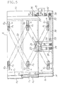
- Fig. 5 is a cross-sectional side view of the working tank 6.
- the pin guides G1, G2 and G3 are provided forward and backward on the base container member 12, the movable frame members 13 and 14, respectively.
- the slide pins P1, P2 and P3 are secured to the ends and joint portions of the pantagraph 20 and can move in respective pin guides G1, G2 and G3, as shown by the arrow m.
- the link pin 27 is rollably secured to the housing member 26 and is engaged with the cross portion of the pantagraph 20.
- the pantagraph 20 vertically expands and contracts. Therefore, the movable frame members 13 and 14 can slide up and down in horizontally supported relation due to the action of the pin guides G1, G2 and G3 and the slide pins P1, P2 and P3.
- the sliding plate 37 in the arm passage portion are guided by plate holding members 42.
- a dam 43 and a dam supporter 44 are provided on the outside of the sliding plate 37 to prevent the entrance of the unwanted substance.
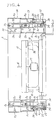
- pantagraph driving means 21 will be described in detail with reference to Fig. 6 and 7.
- the pantagraph driving means 21 includes the frame 22 fixed on the working tank 6.
- the ball screw 25 is uprightly and rotatably supported by the frame 22 through the bearings 23 and 24.
- a worm wheel 28 is secured to a lower part of the ball screw 25.
- the housing member 26 housing a ball screw nut spirally engages the ball screw 25 above the worm wheel 28.
- the housing member 26 includes Y-direction guide rollers 45 and X-direction guide rollers 46 for maintaining the pantagraph 20 upright against a bias load from the dead weight since the movable frame members 13 and 14 are U-shaped.
- the Y-direction guide rollers 45 consist of a pair of rollers which are rollingly contacted to the inner surfaces of the frame 22.
- the pair of rollers are level with the link pin 27 so that the pantagraph 20 may be maintained upright against its fall in the Y-direction.
- the X-direction guide rollers 46 consist of two pairs of rollers. One pair of rollers are level and are rollingly contacted to the surface of the frame 22 facing the pantagraph 20. The other pair of rollers, level with each other, oppose one pair of rollers with respect to the frame and are rollingly contacted to the surface of the frame 22 facing the cover K1. The levels of these two pairs of rollers are vertically offset.
- the centre of the housing member 26 connected to the link pin 27 experiences moments imposed through the link pin 27 by the tank weight loaded to the pin guide G2 and G3.
- the X-direction guide rollers 46 resist the moments to thereby maintain the pantagraph upright against its fall in the X-direction.
- the housing member is stably guided by the frame 22 through the guide rollers 45 and 46 so that an excessive radial load may not be imposed between the ball screw 25 and the ball screw nut.
- the front wall F1 and most of both side walls S1 are lower than the top surface of the work stands 10 for fixing the workpiece 11 to thereby open out forward and toward both sides.
- a tall rear wall R1 including the opening 36 for the passage of the lower arm 15 can move relatively to the lower arm 15.
- the first and second movable frame members 13 and 14 are formed in a U-shape. The movable frame members can slide up to cover the unclosed space of the base container member 12 and can slide down to telescopically overlay upon the low walls F1 and S1 of the base container member 12.
- the movable frame members 13 and 14 will not interfere with the lower arm 15 when they are lowered.
- the movable frame members 13 and 14 are lowered so that the front and both side walls of the tank 6 can be lowered below the workpiece 11. Therefore, forward and both sides access to the workpiece is enabled.
- the dielectric fluid can be filled at the same time of lifting the movable frame members 13 and 14 to restart machining immediately. Machining efficiency is improved.
- multiple sets of the pantagraph 20 and the pantagraph driving means 21 are provided and these sets are synchronized by a single drive motor 32.
- the multiple movable frame members 13 and 14 can be supported at a plurality of fulcra and can move vertically simultaneously in horizontally supported relation.
- the housing member 26 of the pantagraph driving means 21 is guided by the frame 22 through the Y-direction guide rollers 45 and the X-direction guide rollers 46.
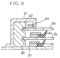
- the locking bent member and the guide rail for guiding the locking bent member is not limited to the embodiment shown in Fig. 1.
- a locking member 61 having a bent portion at its end may be fixedly provided on side wall S1 of the base container member 12.
- a guiding member having guiding grooves 62 and 63 is fitted inside the locking member 61.
- the side wall S2 and S3 of the movable frame members 13 and 14 are guided by the guiding grooves 63 and 62, respectively.
- a stopper 64 is fixed on the outer surface of the side wall S3 so as to engage with the bent portion of the locking member 61.
- Seal members A1 and A2 are provided among side walls S1, S2 and S3. In this arrangement, the movable frame members 13 and 14 are prevented from moving forward due to the fluid pressure.
- the workpiece may be replaced automatically or semi-automatically by associating a conventional NC controller, the dielectric fluid supply device and the lifting device. After machining, the movable frame members may be automatically lowered at the same time as discharging of the dielectric fluid.
- the workpiece may be replaced manually or by an automatic pallet changer. After detecting the end of the workpiece change using a sensor, the dielectric fluid may be supplied into the working tank at the same time as automatically lifting the movable frame members. Machining can then restart.
Landscapes
- Engineering & Computer Science (AREA)
- Mechanical Engineering (AREA)
- Chemical & Material Sciences (AREA)
- Chemical Kinetics & Catalysis (AREA)
- Electrochemistry (AREA)
- Electrical Discharge Machining, Electrochemical Machining, And Combined Machining (AREA)
Applications Claiming Priority (2)
| Application Number | Priority Date | Filing Date | Title |
|---|---|---|---|
| JP216094/92 | 1992-08-13 | ||
| JP21609492A JP3337242B2 (ja) | 1992-08-13 | 1992-08-13 | 浸漬式ワイヤカット放電加工機の加工タンクおよび浸漬式ワイヤカット放電加工機 |
Publications (2)
| Publication Number | Publication Date |
|---|---|
| EP0584990A1 true EP0584990A1 (de) | 1994-03-02 |
| EP0584990B1 EP0584990B1 (de) | 1996-04-10 |
Family
ID=16683158
Family Applications (1)
| Application Number | Title | Priority Date | Filing Date |
|---|---|---|---|
| EP93306275A Expired - Lifetime EP0584990B1 (de) | 1992-08-13 | 1993-08-09 | Drahtschneide-Elektroentladungsmaschine |
Country Status (7)
| Country | Link |
|---|---|
| US (1) | US5401931A (de) |
| EP (1) | EP0584990B1 (de) |
| JP (1) | JP3337242B2 (de) |
| CN (1) | CN1039205C (de) |
| DE (1) | DE69302148T2 (de) |
| HK (1) | HK111396A (de) |
| SG (1) | SG43039A1 (de) |
Families Citing this family (9)
| Publication number | Priority date | Publication date | Assignee | Title |
|---|---|---|---|---|
| DE4330885C1 (de) * | 1993-09-13 | 1995-02-09 | Knecht Hans | Funkenerosionsmaschine |
| DE19640790C2 (de) * | 1996-10-02 | 2001-04-26 | Agie Sa | Verfahren und Vorrichtung zum funkenerosiven Bearbeiten |
| MD3595G2 (ro) * | 2005-03-04 | 2008-12-31 | Технический университет Молдовы | Procedeu şi dispozitiv de prelucrare prin electroeroziune a roţilor dinţate (variante) |
| CN102489804B (zh) * | 2011-11-30 | 2013-07-10 | 苏州三光科技股份有限公司 | 单向走丝线切割机床的密封结构 |
| JP5326024B1 (ja) * | 2012-05-09 | 2013-10-30 | ファナック株式会社 | 放電加工機の加工槽の2段式連動スライドドア |
| CN104023890B (zh) | 2012-10-30 | 2016-02-03 | 三菱电机株式会社 | 线电极放电加工装置 |
| EP3360636B1 (de) * | 2017-02-14 | 2024-06-12 | Agie Charmilles SA | Drahtschneidevorrichtung und verfahren zum trennen von teilen aus einer grundplatte mit einer drahtschneidevorrichtung |
| JP6391867B1 (ja) * | 2018-02-28 | 2018-09-19 | 株式会社ソディック | 放電加工装置 |
| CN117464109B (zh) * | 2023-12-27 | 2024-05-31 | 泰州市斯派特数控机床制造有限公司 | 一种具有调节功能的线切割加工机床 |
Citations (5)
| Publication number | Priority date | Publication date | Assignee | Title |
|---|---|---|---|---|
| EP0186793A2 (de) * | 1984-12-05 | 1986-07-09 | AG für industrielle Elektronik AGIE Losone bei Locarno | Funkenerosionsmaschine mit feststehendem Maschinentisch und absenkbarem Arbeitsbehälter für das Dielektrikum |
| EP0347716A1 (de) * | 1988-06-18 | 1989-12-27 | AEG-Elotherm GmbH | Funkenerosionsmaschine |
| DE3824006A1 (de) * | 1988-07-15 | 1990-01-18 | Schiess Ag | Funkenerosionsmaschine mit feststehendem maschinentisch |
| JPH0248113A (ja) * | 1988-08-05 | 1990-02-16 | Sodick Co Ltd | 放電加工機 |
| EP0410493A1 (de) * | 1989-07-28 | 1991-01-30 | Charmilles Technologies S.A. | Drahtschneide-Funkenerosionsmaschine mit feststehendem Maschinentisch |
Family Cites Families (10)
| Publication number | Priority date | Publication date | Assignee | Title |
|---|---|---|---|---|
| CH654777A5 (fr) * | 1983-07-27 | 1986-03-14 | Charmilles Sa Ateliers | Machine pour decouper par electro-erosion. |
| JPS6062419A (ja) * | 1983-09-12 | 1985-04-10 | Japax Inc | 全自動ワイヤカツト放電加工装置 |
| JPS61173821A (ja) * | 1985-01-24 | 1986-08-05 | Amada Co Ltd | 放電加工装置 |
| JPS61270023A (ja) * | 1985-05-22 | 1986-11-29 | Amada Co Ltd | 放電加工装置 |
| JPH0739056B2 (ja) * | 1988-10-17 | 1995-05-01 | 三菱電機株式会社 | ワイヤ放電加工装置 |
| JP2756488B2 (ja) * | 1989-05-11 | 1998-05-25 | 株式会社ソディック | ワイヤカット放電加工方法及び装置 |
| JPH0457622A (ja) * | 1990-06-25 | 1992-02-25 | Zedomu Kk | 放電加工機 |
| JPH04115818A (ja) * | 1990-09-04 | 1992-04-16 | Amada Washino Co Ltd | 放電加工装置の加工槽 |
| JPH0523918A (ja) * | 1991-07-17 | 1993-02-02 | Mitsubishi Electric Corp | 放電加工装置 |
| JP2818061B2 (ja) * | 1991-12-10 | 1998-10-30 | 三菱電機株式会社 | 放電加工装置 |
-
1992
- 1992-08-13 JP JP21609492A patent/JP3337242B2/ja not_active Expired - Fee Related
-
1993
- 1993-08-09 EP EP93306275A patent/EP0584990B1/de not_active Expired - Lifetime
- 1993-08-09 SG SG1996002829A patent/SG43039A1/en unknown
- 1993-08-09 DE DE69302148T patent/DE69302148T2/de not_active Expired - Lifetime
- 1993-08-12 US US08/104,904 patent/US5401931A/en not_active Expired - Lifetime
- 1993-08-12 CN CN93116229.7A patent/CN1039205C/zh not_active Expired - Lifetime
-
1996
- 1996-06-27 HK HK111396A patent/HK111396A/en not_active IP Right Cessation
Patent Citations (5)
| Publication number | Priority date | Publication date | Assignee | Title |
|---|---|---|---|---|
| EP0186793A2 (de) * | 1984-12-05 | 1986-07-09 | AG für industrielle Elektronik AGIE Losone bei Locarno | Funkenerosionsmaschine mit feststehendem Maschinentisch und absenkbarem Arbeitsbehälter für das Dielektrikum |
| EP0347716A1 (de) * | 1988-06-18 | 1989-12-27 | AEG-Elotherm GmbH | Funkenerosionsmaschine |
| DE3824006A1 (de) * | 1988-07-15 | 1990-01-18 | Schiess Ag | Funkenerosionsmaschine mit feststehendem maschinentisch |
| JPH0248113A (ja) * | 1988-08-05 | 1990-02-16 | Sodick Co Ltd | 放電加工機 |
| EP0410493A1 (de) * | 1989-07-28 | 1991-01-30 | Charmilles Technologies S.A. | Drahtschneide-Funkenerosionsmaschine mit feststehendem Maschinentisch |
Non-Patent Citations (1)
| Title |
|---|
| PATENT ABSTRACTS OF JAPAN vol. 014, no. 212 (M - 0969) 2 May 1990 (1990-05-02) * |
Also Published As
| Publication number | Publication date |
|---|---|
| HK111396A (en) | 1996-07-05 |
| US5401931A (en) | 1995-03-28 |
| DE69302148T2 (de) | 1996-08-29 |
| CN1039205C (zh) | 1998-07-22 |
| SG43039A1 (en) | 1997-10-17 |
| JPH0655349A (ja) | 1994-03-01 |
| EP0584990B1 (de) | 1996-04-10 |
| JP3337242B2 (ja) | 2002-10-21 |
| CN1082472A (zh) | 1994-02-23 |
| DE69302148D1 (de) | 1996-05-15 |
Similar Documents
| Publication | Publication Date | Title |
|---|---|---|
| EP0584990B1 (de) | Drahtschneide-Elektroentladungsmaschine | |
| KR0124546B1 (ko) | 머시닝센터 | |
| KR100401367B1 (ko) | 방전 가공기 및 공작 기계 조립을 위한 모듈 세트 | |
| CA2470875C (en) | Small-hole electrical discharge machining device and multiple diesinking-and-small-hole electrical discharge machining device, and method for multiple diesinking-and-small-hole electrical discharge machining with the same device | |
| US4755651A (en) | Liquid level setting means for electric discharge machine | |
| EP0779124B1 (de) | Drahtschneidefunkenerosionsmaschine | |
| US6246024B1 (en) | Wire electric discharge machining apparatus | |
| US5290987A (en) | Electrical discharge machining apparatus | |
| EP0186793B2 (de) | Funkenerosionsmaschine mit feststehendem Maschinentisch und absenkbarem Arbeitsbehälter für das Dielektrikum | |
| US2981822A (en) | Electrical machining apparatus | |
| CN109202165A (zh) | 上拉式拉床 | |
| KR950011669B1 (ko) | 정지된 피가공물을 가지는 전기부식 와이어 절단 장치 | |
| US5243165A (en) | Wire-cut electroerosion apparatus | |
| US5196666A (en) | Arm sealing device for an edm machine | |
| CN220112887U (zh) | 一种铣削复式加工中心 | |
| EP0667202B1 (de) | Schutzanordnung für die dichtung des bearbeitungsflüssigkeitbehälters einer drahtschneidefunkenerosionsmaschine | |
| JP2889896B2 (ja) | 昇降式加工槽 | |
| JP2858522B2 (ja) | 放電加工装置 | |
| CN222806224U (zh) | 升降油槽电火花加工机床 | |
| CN218535759U (zh) | 一种具有防护功能的压机操控台 | |
| JP3249573B2 (ja) | ワイヤ放電加工機 | |
| CN117207167B (zh) | 一种工作站桌面式工业机器人及其使用方法 | |
| CN214080337U (zh) | 一种具有机内上下料装置的精雕机 | |
| SU498143A1 (ru) | Электроэрозионный станок | |
| WO2025154108A1 (en) | Mobile portal for machine tool with pit arrangement of longitudinal axes |
Legal Events
| Date | Code | Title | Description |
|---|---|---|---|
| PUAI | Public reference made under article 153(3) epc to a published international application that has entered the european phase |
Free format text: ORIGINAL CODE: 0009012 |
|
| AK | Designated contracting states |
Kind code of ref document: A1 Designated state(s): DE FR GB IT |
|
| 17P | Request for examination filed |
Effective date: 19940531 |
|
| 17Q | First examination report despatched |
Effective date: 19950220 |
|
| ITF | It: translation for a ep patent filed | ||
| RAP1 | Party data changed (applicant data changed or rights of an application transferred) |
Owner name: SODICK CO., LTD. |
|
| GRAA | (expected) grant |
Free format text: ORIGINAL CODE: 0009210 |
|
| AK | Designated contracting states |
Kind code of ref document: B1 Designated state(s): DE FR GB IT |
|
| ET | Fr: translation filed | ||
| REF | Corresponds to: |
Ref document number: 69302148 Country of ref document: DE Date of ref document: 19960515 |
|
| PLBE | No opposition filed within time limit |
Free format text: ORIGINAL CODE: 0009261 |
|
| STAA | Information on the status of an ep patent application or granted ep patent |
Free format text: STATUS: NO OPPOSITION FILED WITHIN TIME LIMIT |
|
| 26N | No opposition filed | ||
| REG | Reference to a national code |
Ref country code: GB Ref legal event code: IF02 |
|
| PGFP | Annual fee paid to national office [announced via postgrant information from national office to epo] |
Ref country code: GB Payment date: 20110803 Year of fee payment: 19 Ref country code: FR Payment date: 20110818 Year of fee payment: 19 Ref country code: DE Payment date: 20110803 Year of fee payment: 19 |
|
| PGFP | Annual fee paid to national office [announced via postgrant information from national office to epo] |
Ref country code: IT Payment date: 20110811 Year of fee payment: 19 |
|
| GBPC | Gb: european patent ceased through non-payment of renewal fee |
Effective date: 20120809 |
|
| REG | Reference to a national code |
Ref country code: FR Ref legal event code: ST Effective date: 20130430 |
|
| PG25 | Lapsed in a contracting state [announced via postgrant information from national office to epo] |
Ref country code: IT Free format text: LAPSE BECAUSE OF NON-PAYMENT OF DUE FEES Effective date: 20120809 |
|
| PG25 | Lapsed in a contracting state [announced via postgrant information from national office to epo] |
Ref country code: GB Free format text: LAPSE BECAUSE OF NON-PAYMENT OF DUE FEES Effective date: 20120809 Ref country code: DE Free format text: LAPSE BECAUSE OF NON-PAYMENT OF DUE FEES Effective date: 20130301 |
|
| PG25 | Lapsed in a contracting state [announced via postgrant information from national office to epo] |
Ref country code: FR Free format text: LAPSE BECAUSE OF NON-PAYMENT OF DUE FEES Effective date: 20120831 |
|
| REG | Reference to a national code |
Ref country code: DE Ref legal event code: R119 Ref document number: 69302148 Country of ref document: DE Effective date: 20130301 |