EP0592021A1 - Spritzgiessvorrichtung - Google Patents
Spritzgiessvorrichtung Download PDFInfo
- Publication number
- EP0592021A1 EP0592021A1 EP93202262A EP93202262A EP0592021A1 EP 0592021 A1 EP0592021 A1 EP 0592021A1 EP 93202262 A EP93202262 A EP 93202262A EP 93202262 A EP93202262 A EP 93202262A EP 0592021 A1 EP0592021 A1 EP 0592021A1
- Authority
- EP
- European Patent Office
- Prior art keywords
- receiving
- die
- products
- cavities
- plate
- Prior art date
- Legal status (The legal status is an assumption and is not a legal conclusion. Google has not performed a legal analysis and makes no representation as to the accuracy of the status listed.)
- Granted
Links
Images



Classifications
-
- B—PERFORMING OPERATIONS; TRANSPORTING
- B29—WORKING OF PLASTICS; WORKING OF SUBSTANCES IN A PLASTIC STATE IN GENERAL
- B29C—SHAPING OR JOINING OF PLASTICS; SHAPING OF MATERIAL IN A PLASTIC STATE, NOT OTHERWISE PROVIDED FOR; AFTER-TREATMENT OF THE SHAPED PRODUCTS, e.g. REPAIRING
- B29C45/00—Injection moulding, i.e. forcing the required volume of moulding material through a nozzle into a closed mould; Apparatus therefor
- B29C45/17—Component parts, details or accessories; Auxiliary operations
- B29C45/1769—Handling of moulded articles or runners, e.g. sorting, stacking, grinding of runners
-
- B—PERFORMING OPERATIONS; TRANSPORTING
- B29—WORKING OF PLASTICS; WORKING OF SUBSTANCES IN A PLASTIC STATE IN GENERAL
- B29C—SHAPING OR JOINING OF PLASTICS; SHAPING OF MATERIAL IN A PLASTIC STATE, NOT OTHERWISE PROVIDED FOR; AFTER-TREATMENT OF THE SHAPED PRODUCTS, e.g. REPAIRING
- B29C45/00—Injection moulding, i.e. forcing the required volume of moulding material through a nozzle into a closed mould; Apparatus therefor
- B29C45/17—Component parts, details or accessories; Auxiliary operations
- B29C45/40—Removing or ejecting moulded articles
- B29C45/42—Removing or ejecting moulded articles using means movable from outside the mould between mould parts, e.g. robots
-
- B—PERFORMING OPERATIONS; TRANSPORTING
- B29—WORKING OF PLASTICS; WORKING OF SUBSTANCES IN A PLASTIC STATE IN GENERAL
- B29C—SHAPING OR JOINING OF PLASTICS; SHAPING OF MATERIAL IN A PLASTIC STATE, NOT OTHERWISE PROVIDED FOR; AFTER-TREATMENT OF THE SHAPED PRODUCTS, e.g. REPAIRING
- B29C45/00—Injection moulding, i.e. forcing the required volume of moulding material through a nozzle into a closed mould; Apparatus therefor
- B29C45/17—Component parts, details or accessories; Auxiliary operations
- B29C45/72—Heating or cooling
- B29C45/7207—Heating or cooling of the moulded articles
-
- B—PERFORMING OPERATIONS; TRANSPORTING
- B29—WORKING OF PLASTICS; WORKING OF SUBSTANCES IN A PLASTIC STATE IN GENERAL
- B29C—SHAPING OR JOINING OF PLASTICS; SHAPING OF MATERIAL IN A PLASTIC STATE, NOT OTHERWISE PROVIDED FOR; AFTER-TREATMENT OF THE SHAPED PRODUCTS, e.g. REPAIRING
- B29C45/00—Injection moulding, i.e. forcing the required volume of moulding material through a nozzle into a closed mould; Apparatus therefor
- B29C45/17—Component parts, details or accessories; Auxiliary operations
- B29C45/72—Heating or cooling
- B29C45/7207—Heating or cooling of the moulded articles
- B29C2045/7214—Preform carriers for cooling preforms
- B29C2045/7228—Preform carriers for cooling preforms turret-like
-
- B—PERFORMING OPERATIONS; TRANSPORTING
- B29—WORKING OF PLASTICS; WORKING OF SUBSTANCES IN A PLASTIC STATE IN GENERAL
- B29C—SHAPING OR JOINING OF PLASTICS; SHAPING OF MATERIAL IN A PLASTIC STATE, NOT OTHERWISE PROVIDED FOR; AFTER-TREATMENT OF THE SHAPED PRODUCTS, e.g. REPAIRING
- B29C49/00—Blow-moulding, i.e. blowing a preform or parison to a desired shape within a mould; Apparatus therefor
- B29C49/02—Combined blow-moulding and manufacture of the preform or the parison
- B29C2049/023—Combined blow-moulding and manufacture of the preform or the parison using inherent heat of the preform, i.e. 1 step blow moulding
-
- B—PERFORMING OPERATIONS; TRANSPORTING
- B29—WORKING OF PLASTICS; WORKING OF SUBSTANCES IN A PLASTIC STATE IN GENERAL
- B29C—SHAPING OR JOINING OF PLASTICS; SHAPING OF MATERIAL IN A PLASTIC STATE, NOT OTHERWISE PROVIDED FOR; AFTER-TREATMENT OF THE SHAPED PRODUCTS, e.g. REPAIRING
- B29C31/00—Handling, e.g. feeding of the material to be shaped, storage of plastics material before moulding; Automation, i.e. automated handling lines in plastics processing plants, e.g. using manipulators or robots
-
- B—PERFORMING OPERATIONS; TRANSPORTING
- B29—WORKING OF PLASTICS; WORKING OF SUBSTANCES IN A PLASTIC STATE IN GENERAL
- B29C—SHAPING OR JOINING OF PLASTICS; SHAPING OF MATERIAL IN A PLASTIC STATE, NOT OTHERWISE PROVIDED FOR; AFTER-TREATMENT OF THE SHAPED PRODUCTS, e.g. REPAIRING
- B29C49/00—Blow-moulding, i.e. blowing a preform or parison to a desired shape within a mould; Apparatus therefor
- B29C49/42—Component parts, details or accessories; Auxiliary operations
- B29C49/64—Heating or cooling preforms, parisons or blown articles
- B29C49/6409—Thermal conditioning of preforms
- B29C49/6427—Cooling of preforms
-
- B—PERFORMING OPERATIONS; TRANSPORTING
- B29—WORKING OF PLASTICS; WORKING OF SUBSTANCES IN A PLASTIC STATE IN GENERAL
- B29K—INDEXING SCHEME ASSOCIATED WITH SUBCLASSES B29B, B29C OR B29D, RELATING TO MOULDING MATERIALS OR TO MATERIALS FOR MOULDS, REINFORCEMENTS, FILLERS OR PREFORMED PARTS, e.g. INSERTS
- B29K2105/00—Condition, form or state of moulded material or of the material to be shaped
- B29K2105/25—Solid
- B29K2105/253—Preform
Definitions
- the invention relates to an apparatus for the injection moulding of synthetic products, comprising a die provided with a plurality of cavities, a discharge device and a robot device for receiving the products moulded in the cavities of the die and transferring those products to the discharge device.
- the known apparatus is a machine for producing so-called "preforms" for synthetic containers such as PET (polyethylene terephthalate) bottles.
- the known apparatus has a die comprising a first die half, provided with a plurality of cavities, and a second die half, provided with the same number of cores. In the closed position of the die, the cores extend into the cavities, a space being present around each core in the cavity, which space is to be filled with synthetic material. After the synthetic material has been supplied in fluid form to the cavities and the synthetic material has cooled off sufficiently, the die is opened and a receiving plate of a robot device is brought before the product-carrying member of the die.
- the preforms, after the die has been opened are located on the cores, but it is also possible that, after the die has been opened, the preforms are located in the cavities.
- the receiving plate of the robot device has cavities adapted to receive the products from the cores.
- the receiving plate of the robot device has pins or the like adapted to receive the products from the cavities.
- the die may be provided with ejecting means.
- the receiving plate may be provided with suction means for promoting taking over the products, optionally in combination with ejecting means of the die.
- the moulded products are removed from the die again as quickly as possible so as to obtain a shortest possible cycle period.
- the robot device should be ready again to take over the next set of preforms at the end of the next injection moulding cycle, this also means that the preforms can stay in the robot device only briefly and that the preforms are still very warm and vulnerable at the moment when the robot device delivers the preforms again to the discharge device.
- the discharge device comprises a conveyor belt and during the stay on the conveyor belt the preforms are cooled by air and/or fluid.
- the receiving plate be provided with a number of receiving means for moulded products that is a multiple of the number of cavities of the die.
- the moulded products such as preforms, can stay in the cooled carrier plate for more than one cycle period and be cooled relatively long before the products are transferred to the discharge device.
- a drawback of this known apparatus is that the receiving plate becomes large and heavy. Because the carrier plate should be moved back again between the die halves at the end of each injection moulding cycle, a quick reciprocating movement is necessary, which requires more energy as the mass of the receiving plate increases and which is moreover slowed down abruptly each time. Moreover, this quick reciprocating movement, stopping abruptly each time at the end of the path to be traversed by the receiving plate, increases the chance of damage to the products which are still located in the receiving plate.
- the object of the invention is to overcome the above-mentioned drawbacks and generally to provide an improved injection moulding apparatus which on the one hand allows for very short cycle periods, while on the other hand the chance of damage to moulded products is very slight.
- an apparatus of the above-described type is characterized in that the robot device comprises at least two receiving plates, each adapted to receive a number of moulded products equal to at least once the number of cavities of the die, and drive means for successively bringing the receiving plates into a receiving position next to the die, and for bringing a receiving plate from the receiving position into a take-over position and back again, in which take-over position the moulded products can be taken over from the die.
- Fig. 1 schematically shows a view of a known injection moulding apparatus 1 for preforms for PET bottles.
- the apparatus shown has a die 2, in this example mounted in vertical position on a base 3.
- the die 2 consists of two members, movable relatively to each other between a closed and an open position of the die, in horizontal direction transverse to the plane of the drawing.
- One die member has a plurality of substantially cylindrical cavities and the other die member has the same number of bar-shaped cores, in the closed position of the die extending into the cavities. In the closed position of the die, a narrow clearance is present around the cores, into which hot fluid synthetic material can be injected to mould the preforms.
- the die is opened.
- at least one of the die members is movable relatively to the other die member along guides 4. This involves the preforms being left behind either in the cavities or on the cores.
- the die comprises two rows of eight cavities and cores, designated by 5 and 6 respectively.
- the injection moulding apparatus further comprises a robot device, of which only the receiving plate 7 is shown schematically.
- the receiving plate is provided with receiving means 8 having a receiving cavity adapted to take over the preforms from the die member provided with cores.
- the receiving plate can be brought from a position outside the die into a position opposite the die member provided with cores. Taking over takes place through means known for that purpose, such as, for instance, a stripper plate, not shown.
- the die can be closed again for a next cycle. During that next cycle, the robot device moves the receiving plate to above a discharge device 12.
- the receiving plate is drawn in a position in which the receiving plate is ready to be brought between the die halves, as indicated by an arrow 9.
- the receiving plate is shown just before the preforms, designated by 10, are transferred onto the discharge device. The path of movement between the two positions is schematically shown at 11.
- the discharge device 12 comprises a conveying belt 14 provided with pins 13.
- the preforms are placed onto the pins 13 by the receiving plate and subsequently discharged to a collecting device 15, shown schematically.
- the receiving plate 7 is adapted to receive twice as many preforms as can be moulded in the die per injection moulding cycle. Therefore, the receiving plate is filled in two successive cycles and accordingly transfers the preforms onto the discharge device in two successive cycles. Hence, the preforms moulded during an injection moulding cycle can cool off in the receiving plate each time during the subsequent injection moulding cycle and are only then taken over by the discharge device.
- Fig. 2 schematically shows a view of an example of an apparatus 20 according to the invention.
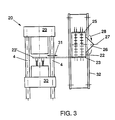
- the apparatus shown in Fig. 2 is shown schematically in top plan view in Fig. 3 and in this example has a die 2 with two rows 5,6 of eight moulding cavities similar to that of the known apparatus of Fig. 1.
- the injection moulding apparatus 20 of Fig. 2 differs from the known apparatus 10 of Fig. 1 in that the robot device 21 has four receiving plates 22,23,24 and 25, three of which are visible in Figs 2 and 3.
- the receiving plates are mounted on a turret, schematically designated by 26 in Figs 2 and 3, capable of rotating around a shaft 27 as indicated by an arrow 28.
- the turret 26 is disposed next to the die in such a manner that when the die is open, one of the receiving plates can each time be inserted between the die halves 29,30 to receive the moulded products, as indicated in Fig. 3 at 23' by interrupted lines and by an arrow 31.
- each receiving plate has as many receiving locations as the number of moulding cavities of the die.
- each receiving plate has four positions, taken up during successive injection moulding cycles. These are a receiving position, a first and a second cooling position, and an ejecting position. In Figs 2 and 3, the receiving plate 23 is in the receiving position, while plate 24 is in the ejecting position. The plates 22 and 25 are in the cooling positions.
- the plate 24 takes up the receiving position and the plate 25 takes up the ejecting position. Accordingly, the plates 22 and 23 are in the first and second cooling positions.
- the receiving plate should be available again for receiving newly moulded products only after four injection moulding cycles, so that the products can cool for a relatively long period.
- the plate As soon as a receiving plate of the robot device has been filled with newly moulded products, the plate has to make only one linear movement from the position between the die halves to the rest position. Braking may be effected relatively slowly, because the same plate is moved between the die halves only after a number of injection moulding cycles. Between these two linear movements only one rotation of the turret takes place, which may also be effected relatively slowly. Hence, the chance of damage to the products, still soft, as a consequence of the movements carried out by the receiving plate is very small.
- FIG. 4 shows in side view a robot device with a turret according to the invention, disposed next to a die for moulding preforms.
- the robot device 40 comprises a base 41, carrying a turret 43 rotatable around a shaft 42.
- the shaft 42 is a horizontal shaft, but a different orientation is possible. It is important that the turret be positioned relatively to the die 50 in such a manner that the receiving plates, each in one of the positions of the turret, can be inserted between the die halves in a simple manner, preferably in a linear movement.
- the die has six rows of eight moulding cavities.
- the turret comprises four receiving plates, each of which also has six rows of eight receiving locations for moulded products.
- Fig. 5 shows the turret of Fig. 4 in end view without the base. Each plate successively takes up the receiving position A, the cooling positions B and C and the delivery position D, with the turret rotating in the direction of the arrow 48.
- Fig. 6 shows in top plan view the die 50 with the die halves 50a and 50b in the moved-apart position.
- the receiving plate 44 can be moved before the die half 50a carrying the moulded products.
- the turret in this example is provided with at least one extensible arm 52, carrying the plate which is in position A, as is shown in Fig. 7.
- the desired movements of the receiving plates can be realized in various manners known per se by means of pneumatic, hydraulic or electric drive means. It is possible to mount each plate on an extension arm, energized as soon as the plate is in the receiving position. It is also possible to apply a stationary extension arm, each time engaging and carrying the receiving plate, which is in the receiving position at a particular moment.
- the receiving plates may or may not be provided with cooling channels or the like.
- Fig. 8 and Fig. 9 each show a portion of a receiving plate 60 comprising receiving means 61 adapted to the product, in this example designed as loose adaptors.
- Fig. 8 shows a preform 62, partially accommodated in the adaptor 61 and having a sprue 63 at its end extending into the adaptor.
Landscapes
- Engineering & Computer Science (AREA)
- Manufacturing & Machinery (AREA)
- Mechanical Engineering (AREA)
- Robotics (AREA)
- Moulds For Moulding Plastics Or The Like (AREA)
- Injection Moulding Of Plastics Or The Like (AREA)
- Blow-Moulding Or Thermoforming Of Plastics Or The Like (AREA)
Applications Claiming Priority (3)
| Application Number | Priority Date | Filing Date | Title |
|---|---|---|---|
| NL9201738 | 1992-10-08 | ||
| NL9201738A NL9201738A (nl) | 1992-10-08 | 1992-10-08 | Spuitgietinrichting. |
| US08/421,160 US5569476A (en) | 1992-10-08 | 1995-04-10 | Injection molding machine having a rotatable turret |
Publications (2)
| Publication Number | Publication Date |
|---|---|
| EP0592021A1 true EP0592021A1 (de) | 1994-04-13 |
| EP0592021B1 EP0592021B1 (de) | 1997-12-03 |
Family
ID=26647021
Family Applications (1)
| Application Number | Title | Priority Date | Filing Date |
|---|---|---|---|
| EP93202262A Expired - Lifetime EP0592021B1 (de) | 1992-10-08 | 1993-07-30 | Spritzgiessvorrichtung |
Country Status (3)
| Country | Link |
|---|---|
| US (1) | US5569476A (de) |
| EP (1) | EP0592021B1 (de) |
| NL (1) | NL9201738A (de) |
Cited By (10)
| Publication number | Priority date | Publication date | Assignee | Title |
|---|---|---|---|---|
| WO1994016871A1 (en) * | 1993-01-20 | 1994-08-04 | Serviplast | Method and apparatus for manufacturing hollow objects, in particular plastic preforms |
| NL1001087C2 (nl) * | 1995-08-29 | 1997-03-03 | Inter Tooling Services Bv | Spuitgietinrichting voor het vervaardigen van holle kunststof voorwerpen. |
| NL1003683C2 (nl) * | 1996-07-25 | 1998-01-28 | Inter Tooling Services Bv | Spuitgietinrichting voor het vervaardigen van holle kunststof voorwerpen, en robot voor een dergelijke spuitgietinrichting. |
| NL1013770C2 (nl) * | 1999-12-06 | 2001-06-07 | Inter Tooling Services Bv | Spuitgietinrichting met robotinrichting en mechanische uittrekinrichting voor het verwijderen van preforms uit de robotinrichting, alsmede robotinrichting voor een spuitgietinrichting. |
| DE10147554A1 (de) * | 2001-09-26 | 2003-04-10 | Ursula Luckow | Verfahren und Vorrichtung zur Formung und Handhabung von Werkstücken |
| WO2005037522A1 (en) * | 2003-10-07 | 2005-04-28 | S.I.P.A. Società Industrializzazione Progettazione E Automazione S.P.A. | Conditioning device for plastic items and process |
| WO2005084915A1 (en) * | 2004-03-02 | 2005-09-15 | S.I.P.A. Società Industrializzazione Progettazione E Automazione S.P.A. | Device for conditioning plastic objects and respective conditioning method |
| NL1026732C2 (nl) * | 2004-07-27 | 2006-01-30 | Tool Tech Holding B V | Koelinrichting voor preforms van kunststof houders, alsmede robotinrichting voorzien van een dergelijke koelinrichting en productie-inrichting voor preforms voorzien van een dergelijke robotinrichting. |
| WO2011145913A1 (es) * | 2010-05-21 | 2011-11-24 | Cortes Botello Fernando | Equipo enfriador de fondo de botellas plásticas recién moldeadas |
| WO2016124396A1 (de) | 2015-02-05 | 2016-08-11 | Foboha (Germany) Gmbh | Spritzgiessvorrichtung zum herstellen von teilen aus kunststoff |
Families Citing this family (18)
| Publication number | Priority date | Publication date | Assignee | Title |
|---|---|---|---|---|
| US5707662A (en) * | 1995-11-01 | 1998-01-13 | Electra Form, Inc. | Parison molding and cooling apparatus |
| US5855932A (en) * | 1996-09-13 | 1999-01-05 | Electra Form, Inc. | Molded article retrieval apparatus |
| US6062845A (en) * | 1998-03-19 | 2000-05-16 | Graham Engineering Corporation | Take-out mechanism for blow molding machine |
| US6299431B1 (en) | 1998-07-28 | 2001-10-09 | Husky Injection Molding Systems Ltd. | Cooling apparatus for injection molding machines |
| US6296473B1 (en) * | 1998-08-18 | 2001-10-02 | Ventax Robot Inc. | Handling and cooling system for plastic container preforms |
| US6143225A (en) * | 1999-03-03 | 2000-11-07 | Husky Injection Molding Systems Ltd. | Turret cooling block for an index machine |
| ITPN20000006A1 (it) * | 2000-01-26 | 2001-07-26 | Sipa Spa | Impianto a torre rotante su asse orizzontale per la movimentazione dipreforme |
| DE10029154B4 (de) * | 2000-06-19 | 2005-05-12 | Hekuma Gmbh | Vorrichtung zum Spritzgießen von Kunststoffartikeln |
| US6817855B2 (en) * | 2002-05-17 | 2004-11-16 | Husky Injection Molding Systems Ltd. | Apparatus for post mold cooling of plastic pieces |
| AU2003267163A1 (en) * | 2002-09-13 | 2004-04-30 | Ultra Tool Group, Lp | Injection molding equipment having molded article ejector, and method |
| US7175413B1 (en) * | 2002-09-23 | 2007-02-13 | Owens-Illinois Closure Inc. | Elastomeric dispensing valve manufacture |
| US7128553B2 (en) | 2003-09-26 | 2006-10-31 | Advance Tool, Inc. | Injection molding apparatus and method |
| ITRM20030460A1 (it) * | 2003-10-07 | 2005-04-08 | Sipa Societa Industrializzazione P Rogettazione A | Dispositivo e processo di iniezione di oggetti in materia plastica. |
| ITRM20040107A1 (it) * | 2004-03-02 | 2004-06-02 | Sipa Societa Industrializzazio | Dispositivo e metodo di condizionamento di oggetti in plastica. |
| US7293980B2 (en) * | 2005-03-10 | 2007-11-13 | Husky Injection Molding Systems Ltd. | Porous member for a post-molding molded article conditioning apparatus with an integrally formed cooling structure |
| BE1016968A3 (nl) * | 2006-01-27 | 2007-11-06 | Boucherie Nv G B | Inrichting voor het vervaardigen van spuitgietstukken. |
| US7946836B2 (en) * | 2008-05-23 | 2011-05-24 | Roberto Sicilia | Injection molding and temperature conditioning apparatus |
| RU2384411C1 (ru) * | 2008-12-18 | 2010-03-20 | Открытое Акционерное Общество "СИГОМАТИК" | Поворотная головка |
Citations (5)
| Publication number | Priority date | Publication date | Assignee | Title |
|---|---|---|---|---|
| DE2160987A1 (de) * | 1971-12-09 | 1973-06-20 | Gabler Gmbh Maschbau | Entnahmevorrichtung fuer die gussstuecke einer druckgussmaschine oder dgl |
| GB2084907A (en) * | 1980-09-26 | 1982-04-21 | Herrmann Prazisionsdruckguss G | Die casting or injection moulding apparatus |
| JPS58158209A (ja) * | 1982-03-15 | 1983-09-20 | Shin Etsu Polymer Co Ltd | 射出成形品の自動取出しおよび自動仕上げ装置 |
| EP0283644A2 (de) * | 1987-03-23 | 1988-09-28 | Husky Injection Molding Systems Ltd. | Vorrichtung zum Herstellen von hohlen Artikeln aus Kunststoff |
| US5114327A (en) * | 1991-01-25 | 1992-05-19 | Williamson James T | Rapid cooling apparatus for an injection molding machine |
Family Cites Families (2)
| Publication number | Priority date | Publication date | Assignee | Title |
|---|---|---|---|---|
| GB283644A (en) * | 1926-10-14 | 1928-01-16 | Duplo Ges Mit Beschraenkter Ha | Improvements relating to high-pressure grease guns |
| US4836767A (en) * | 1987-11-25 | 1989-06-06 | Husky Injection Molding System, Ltd. | Swing plate molding machine |
-
1992
- 1992-10-08 NL NL9201738A patent/NL9201738A/nl not_active Application Discontinuation
-
1993
- 1993-07-30 EP EP93202262A patent/EP0592021B1/de not_active Expired - Lifetime
-
1995
- 1995-04-10 US US08/421,160 patent/US5569476A/en not_active Expired - Lifetime
Patent Citations (5)
| Publication number | Priority date | Publication date | Assignee | Title |
|---|---|---|---|---|
| DE2160987A1 (de) * | 1971-12-09 | 1973-06-20 | Gabler Gmbh Maschbau | Entnahmevorrichtung fuer die gussstuecke einer druckgussmaschine oder dgl |
| GB2084907A (en) * | 1980-09-26 | 1982-04-21 | Herrmann Prazisionsdruckguss G | Die casting or injection moulding apparatus |
| JPS58158209A (ja) * | 1982-03-15 | 1983-09-20 | Shin Etsu Polymer Co Ltd | 射出成形品の自動取出しおよび自動仕上げ装置 |
| EP0283644A2 (de) * | 1987-03-23 | 1988-09-28 | Husky Injection Molding Systems Ltd. | Vorrichtung zum Herstellen von hohlen Artikeln aus Kunststoff |
| US5114327A (en) * | 1991-01-25 | 1992-05-19 | Williamson James T | Rapid cooling apparatus for an injection molding machine |
Non-Patent Citations (1)
| Title |
|---|
| PATENT ABSTRACTS OF JAPAN vol. 7, no. 283 (M - 263)<1428> 16 December 1983 (1983-12-16) * |
Cited By (17)
| Publication number | Priority date | Publication date | Assignee | Title |
|---|---|---|---|---|
| WO1994016871A1 (en) * | 1993-01-20 | 1994-08-04 | Serviplast | Method and apparatus for manufacturing hollow objects, in particular plastic preforms |
| US5744088A (en) * | 1993-01-20 | 1998-04-28 | Simeco | Method and apparatus for manufcturing hollow objects, in particular plastic preforms |
| NL1001087C2 (nl) * | 1995-08-29 | 1997-03-03 | Inter Tooling Services Bv | Spuitgietinrichting voor het vervaardigen van holle kunststof voorwerpen. |
| EP0764513A1 (de) * | 1995-08-29 | 1997-03-26 | Inter Tooling Services B.V. | Spritzgiessvorrichtung zur Herstellung von Hohlkörpern aus Kunststoff |
| NL1003683C2 (nl) * | 1996-07-25 | 1998-01-28 | Inter Tooling Services Bv | Spuitgietinrichting voor het vervaardigen van holle kunststof voorwerpen, en robot voor een dergelijke spuitgietinrichting. |
| NL1013770C2 (nl) * | 1999-12-06 | 2001-06-07 | Inter Tooling Services Bv | Spuitgietinrichting met robotinrichting en mechanische uittrekinrichting voor het verwijderen van preforms uit de robotinrichting, alsmede robotinrichting voor een spuitgietinrichting. |
| EP1106324A1 (de) * | 1999-12-06 | 2001-06-13 | Inter Tooling Services B.V. | Spritzgiessapparat mit Robotervorrichtung und mechanischer Auszieheinheit zum Entfernen von Vorformlingen aus der Robotervorrichtung, und Robotervorrichtung für einen Spritzgiessapparat |
| US6520765B2 (en) | 1999-12-06 | 2003-02-18 | Inter Tooling Services B.V. | Injection molding apparatus with robot device and mechanical pull-out unit for removing preforms from the robot device, and robot device for an injection molding apparatus |
| DE10147554A1 (de) * | 2001-09-26 | 2003-04-10 | Ursula Luckow | Verfahren und Vorrichtung zur Formung und Handhabung von Werkstücken |
| WO2005037522A1 (en) * | 2003-10-07 | 2005-04-28 | S.I.P.A. Società Industrializzazione Progettazione E Automazione S.P.A. | Conditioning device for plastic items and process |
| US8246338B2 (en) | 2003-10-07 | 2012-08-21 | S.I.P.A. Societa Industrializzazione Progettazione E Automazione S.P.A. | Conditioning device for plastic items and process |
| WO2005084915A1 (en) * | 2004-03-02 | 2005-09-15 | S.I.P.A. Società Industrializzazione Progettazione E Automazione S.P.A. | Device for conditioning plastic objects and respective conditioning method |
| NL1026732C2 (nl) * | 2004-07-27 | 2006-01-30 | Tool Tech Holding B V | Koelinrichting voor preforms van kunststof houders, alsmede robotinrichting voorzien van een dergelijke koelinrichting en productie-inrichting voor preforms voorzien van een dergelijke robotinrichting. |
| EP1621318A1 (de) * | 2004-07-27 | 2006-02-01 | Tool-Tech Holding B.V. | Vorrichtung zum Kühlen von Vorformlingen, sowie eine Entnahmevorrichtung und Vorrichtung zur Herstellung mit einer solchen Vorrichtung |
| WO2011145913A1 (es) * | 2010-05-21 | 2011-11-24 | Cortes Botello Fernando | Equipo enfriador de fondo de botellas plásticas recién moldeadas |
| WO2016124396A1 (de) | 2015-02-05 | 2016-08-11 | Foboha (Germany) Gmbh | Spritzgiessvorrichtung zum herstellen von teilen aus kunststoff |
| US11045986B2 (en) | 2015-02-05 | 2021-06-29 | Foboha (Germany) Gmbh | Injection moulding device for producing parts made of plastic |
Also Published As
| Publication number | Publication date |
|---|---|
| EP0592021B1 (de) | 1997-12-03 |
| US5569476A (en) | 1996-10-29 |
| NL9201738A (nl) | 1994-05-02 |
Similar Documents
| Publication | Publication Date | Title |
|---|---|---|
| EP0592021B1 (de) | Spritzgiessvorrichtung | |
| US4721452A (en) | Apparatus for producing hollow plastic articles | |
| USRE33237E (en) | Apparatus for producing hollow plastic articles | |
| US5037597A (en) | Unloading and assembly system and process for injection molding apparatus | |
| KR100742923B1 (ko) | 플래튼이 장착된 성형 후 냉각 장치 | |
| EP0873840B1 (de) | Spritzgiessmaschine zur Herstellung von Hohlkörpern aus Kunststoff | |
| EP0686081B1 (de) | Verfahren und vorrichtung zur herstellung von hohlkörpern insbesondere vorformen aus kunststoff | |
| US3964847A (en) | Continuous automated plastic molding apparatus | |
| US6767203B2 (en) | Horizontal-axis revolving-turret plant for handling preforms | |
| US5053173A (en) | Process and apparatus for manufacturing plastic mouldings | |
| US6290891B1 (en) | Cooling process for molded articles | |
| EP0688651A1 (de) | Spritzgiessmaschine und Verfahren zur Herstellung von Hohlkörpern aus Kunststoff | |
| US3266086A (en) | Molding apparatus | |
| EP0982113A2 (de) | Handling- und Kühlsystem für Behältervorformlinge aus Kunststoff | |
| EP1673209B1 (de) | Vorrichtung und verfahren zum extrahieren von kunststoffgegenständen | |
| US5169653A (en) | Label transfer mechanism for blow molding machinery | |
| RU2352461C2 (ru) | Устройство для кондиционирования пластмассовых предметов и способ их кондиционирования | |
| CA2146741C (en) | Injection moulding apparatus | |
| EP1286817B1 (de) | Vorrichtung und verfahren zum handhaben und zur kühlung von kunststoffvorformlingen | |
| US3981956A (en) | Continuous automated plastic molding method | |
| US3851030A (en) | Method for the production of composite containers | |
| US11045986B2 (en) | Injection moulding device for producing parts made of plastic | |
| GB1184111A (en) | Improvements relating to Apparatus for the Production of Gramophone Records | |
| US3920374A (en) | Apparatus for stripping and unloading a molded part from a mold core | |
| US7331779B2 (en) | Concurrent cooling mold |
Legal Events
| Date | Code | Title | Description |
|---|---|---|---|
| PUAI | Public reference made under article 153(3) epc to a published international application that has entered the european phase |
Free format text: ORIGINAL CODE: 0009012 |
|
| AK | Designated contracting states |
Kind code of ref document: A1 Designated state(s): BE DE FR GB IT LU NL |
|
| 17P | Request for examination filed |
Effective date: 19941011 |
|
| 17Q | First examination report despatched |
Effective date: 19960628 |
|
| GRAG | Despatch of communication of intention to grant |
Free format text: ORIGINAL CODE: EPIDOS AGRA |
|
| GRAG | Despatch of communication of intention to grant |
Free format text: ORIGINAL CODE: EPIDOS AGRA |
|
| GRAH | Despatch of communication of intention to grant a patent |
Free format text: ORIGINAL CODE: EPIDOS IGRA |
|
| GRAH | Despatch of communication of intention to grant a patent |
Free format text: ORIGINAL CODE: EPIDOS IGRA |
|
| GRAA | (expected) grant |
Free format text: ORIGINAL CODE: 0009210 |
|
| AK | Designated contracting states |
Kind code of ref document: B1 Designated state(s): BE DE FR GB IT LU NL |
|
| REF | Corresponds to: |
Ref document number: 69315530 Country of ref document: DE Date of ref document: 19980115 |
|
| ITF | It: translation for a ep patent filed | ||
| ET | Fr: translation filed | ||
| PLBE | No opposition filed within time limit |
Free format text: ORIGINAL CODE: 0009261 |
|
| 26N | No opposition filed | ||
| REG | Reference to a national code |
Ref country code: GB Ref legal event code: IF02 |
|
| PGFP | Annual fee paid to national office [announced via postgrant information from national office to epo] |
Ref country code: DE Payment date: 20080725 Year of fee payment: 16 |
|
| PGFP | Annual fee paid to national office [announced via postgrant information from national office to epo] |
Ref country code: NL Payment date: 20080715 Year of fee payment: 16 Ref country code: FR Payment date: 20080617 Year of fee payment: 16 |
|
| PGFP | Annual fee paid to national office [announced via postgrant information from national office to epo] |
Ref country code: GB Payment date: 20080728 Year of fee payment: 16 |
|
| PGFP | Annual fee paid to national office [announced via postgrant information from national office to epo] |
Ref country code: BE Payment date: 20080709 Year of fee payment: 16 |
|
| BERE | Be: lapsed |
Owner name: *INTER TOOLING SERVICES B.V. Effective date: 20090731 |
|
| GBPC | Gb: european patent ceased through non-payment of renewal fee |
Effective date: 20090730 |
|
| NLV4 | Nl: lapsed or anulled due to non-payment of the annual fee |
Effective date: 20100201 |
|
| REG | Reference to a national code |
Ref country code: FR Ref legal event code: ST Effective date: 20100331 |
|
| PG25 | Lapsed in a contracting state [announced via postgrant information from national office to epo] |
Ref country code: FR Free format text: LAPSE BECAUSE OF NON-PAYMENT OF DUE FEES Effective date: 20090731 |
|
| PG25 | Lapsed in a contracting state [announced via postgrant information from national office to epo] |
Ref country code: GB Free format text: LAPSE BECAUSE OF NON-PAYMENT OF DUE FEES Effective date: 20090730 |
|
| PG25 | Lapsed in a contracting state [announced via postgrant information from national office to epo] |
Ref country code: DE Free format text: LAPSE BECAUSE OF NON-PAYMENT OF DUE FEES Effective date: 20100202 Ref country code: BE Free format text: LAPSE BECAUSE OF NON-PAYMENT OF DUE FEES Effective date: 20090731 |
|
| PGFP | Annual fee paid to national office [announced via postgrant information from national office to epo] |
Ref country code: LU Payment date: 20100726 Year of fee payment: 18 Ref country code: IT Payment date: 20100726 Year of fee payment: 18 |
|
| PG25 | Lapsed in a contracting state [announced via postgrant information from national office to epo] |
Ref country code: IT Free format text: LAPSE BECAUSE OF NON-PAYMENT OF DUE FEES Effective date: 20110730 |
|
| PG25 | Lapsed in a contracting state [announced via postgrant information from national office to epo] |
Ref country code: NL Free format text: LAPSE BECAUSE OF NON-PAYMENT OF DUE FEES Effective date: 20100201 |
|
| PG25 | Lapsed in a contracting state [announced via postgrant information from national office to epo] |
Ref country code: LU Free format text: LAPSE BECAUSE OF NON-PAYMENT OF DUE FEES Effective date: 20110730 |