EP0592372A2 - Transportable reverse osmosis water purification unit - Google Patents
Transportable reverse osmosis water purification unit Download PDFInfo
- Publication number
- EP0592372A2 EP0592372A2 EP93810709A EP93810709A EP0592372A2 EP 0592372 A2 EP0592372 A2 EP 0592372A2 EP 93810709 A EP93810709 A EP 93810709A EP 93810709 A EP93810709 A EP 93810709A EP 0592372 A2 EP0592372 A2 EP 0592372A2
- Authority
- EP
- European Patent Office
- Prior art keywords
- pass
- permeate
- reverse osmosis
- water
- modules
- Prior art date
- Legal status (The legal status is an assumption and is not a legal conclusion. Google has not performed a legal analysis and makes no representation as to the accuracy of the status listed.)
- Granted
Links
- XLYOFNOQVPJJNP-UHFFFAOYSA-N water Substances O XLYOFNOQVPJJNP-UHFFFAOYSA-N 0.000 title claims abstract description 96
- 238000001223 reverse osmosis Methods 0.000 title claims abstract description 29
- 238000000746 purification Methods 0.000 title claims abstract description 28
- 239000012466 permeate Substances 0.000 claims abstract description 73
- 239000012141 concentrate Substances 0.000 claims abstract description 35
- 238000004140 cleaning Methods 0.000 claims description 65
- 239000012528 membrane Substances 0.000 claims description 25
- 239000000243 solution Substances 0.000 claims description 25
- 238000000034 method Methods 0.000 claims description 20
- 230000008569 process Effects 0.000 claims description 19
- 238000011010 flushing procedure Methods 0.000 claims description 18
- 239000000126 substance Substances 0.000 claims description 14
- 238000003860 storage Methods 0.000 claims description 11
- ZAMOUSCENKQFHK-UHFFFAOYSA-N Chlorine atom Chemical compound [Cl] ZAMOUSCENKQFHK-UHFFFAOYSA-N 0.000 claims description 10
- 239000000460 chlorine Substances 0.000 claims description 10
- 229910052801 chlorine Inorganic materials 0.000 claims description 10
- 230000005611 electricity Effects 0.000 claims description 5
- 239000000446 fuel Substances 0.000 claims description 5
- 238000002347 injection Methods 0.000 claims description 5
- 239000007924 injection Substances 0.000 claims description 5
- 238000004519 manufacturing process Methods 0.000 claims description 5
- 238000001914 filtration Methods 0.000 claims description 4
- 239000012530 fluid Substances 0.000 claims description 4
- 239000004215 Carbon black (E152) Substances 0.000 claims description 3
- 238000004891 communication Methods 0.000 claims description 3
- 229930195733 hydrocarbon Natural products 0.000 claims description 3
- 150000002430 hydrocarbons Chemical class 0.000 claims description 3
- 238000011144 upstream manufacturing Methods 0.000 claims description 2
- 239000007787 solid Substances 0.000 abstract description 10
- 239000000969 carrier Substances 0.000 abstract 1
- 235000012206 bottled water Nutrition 0.000 description 7
- 239000003651 drinking water Substances 0.000 description 7
- 239000002516 radical scavenger Substances 0.000 description 6
- 239000000356 contaminant Substances 0.000 description 5
- 239000013535 sea water Substances 0.000 description 5
- 230000035939 shock Effects 0.000 description 5
- 238000011001 backwashing Methods 0.000 description 4
- 239000000701 coagulant Substances 0.000 description 4
- 238000013461 design Methods 0.000 description 4
- 238000009826 distribution Methods 0.000 description 4
- 239000006096 absorbing agent Substances 0.000 description 3
- KRKNYBCHXYNGOX-UHFFFAOYSA-N citric acid Chemical compound OC(=O)CC(O)(C(O)=O)CC(O)=O KRKNYBCHXYNGOX-UHFFFAOYSA-N 0.000 description 3
- 230000007812 deficiency Effects 0.000 description 3
- 239000002828 fuel tank Substances 0.000 description 3
- OKTJSMMVPCPJKN-UHFFFAOYSA-N Carbon Chemical compound [C] OKTJSMMVPCPJKN-UHFFFAOYSA-N 0.000 description 2
- FAPWRFPIFSIZLT-UHFFFAOYSA-M Sodium chloride Chemical compound [Na+].[Cl-] FAPWRFPIFSIZLT-UHFFFAOYSA-M 0.000 description 2
- 230000008901 benefit Effects 0.000 description 2
- 239000003795 chemical substances by application Substances 0.000 description 2
- 238000010586 diagram Methods 0.000 description 2
- 230000003204 osmotic effect Effects 0.000 description 2
- 230000010349 pulsation Effects 0.000 description 2
- 229910001220 stainless steel Inorganic materials 0.000 description 2
- 239000010935 stainless steel Substances 0.000 description 2
- ZKQDCIXGCQPQNV-UHFFFAOYSA-N Calcium hypochlorite Chemical compound [Ca+2].Cl[O-].Cl[O-] ZKQDCIXGCQPQNV-UHFFFAOYSA-N 0.000 description 1
- 230000001154 acute effect Effects 0.000 description 1
- 230000002411 adverse Effects 0.000 description 1
- 230000008859 change Effects 0.000 description 1
- 239000002575 chemical warfare agent Substances 0.000 description 1
- 238000005660 chlorination reaction Methods 0.000 description 1
- 238000001816 cooling Methods 0.000 description 1
- 230000007423 decrease Effects 0.000 description 1
- 238000011161 development Methods 0.000 description 1
- 239000002283 diesel fuel Substances 0.000 description 1
- 230000009977 dual effect Effects 0.000 description 1
- 230000000694 effects Effects 0.000 description 1
- 238000005516 engineering process Methods 0.000 description 1
- 239000004744 fabric Substances 0.000 description 1
- 238000007710 freezing Methods 0.000 description 1
- 239000013505 freshwater Substances 0.000 description 1
- 230000006872 improvement Effects 0.000 description 1
- 239000003112 inhibitor Substances 0.000 description 1
- 238000009413 insulation Methods 0.000 description 1
- 238000005342 ion exchange Methods 0.000 description 1
- 150000002500 ions Chemical class 0.000 description 1
- JEIPFZHSYJVQDO-UHFFFAOYSA-N iron(III) oxide Inorganic materials O=[Fe]O[Fe]=O JEIPFZHSYJVQDO-UHFFFAOYSA-N 0.000 description 1
- 230000002045 lasting effect Effects 0.000 description 1
- 230000008520 organization Effects 0.000 description 1
- 238000011045 prefiltration Methods 0.000 description 1
- 238000005086 pumping Methods 0.000 description 1
- 230000001105 regulatory effect Effects 0.000 description 1
- 238000012827 research and development Methods 0.000 description 1
- 239000002455 scale inhibitor Substances 0.000 description 1
- 238000013341 scale-up Methods 0.000 description 1
- 239000008399 tap water Substances 0.000 description 1
- 235000020679 tap water Nutrition 0.000 description 1
- 239000012498 ultrapure water Substances 0.000 description 1
- 238000005406 washing Methods 0.000 description 1
Images


Classifications
-
- B—PERFORMING OPERATIONS; TRANSPORTING
- B01—PHYSICAL OR CHEMICAL PROCESSES OR APPARATUS IN GENERAL
- B01D—SEPARATION
- B01D61/00—Processes of separation using semi-permeable membranes, e.g. dialysis, osmosis or ultrafiltration; Apparatus, accessories or auxiliary operations specially adapted therefor
- B01D61/02—Reverse osmosis; Hyperfiltration ; Nanofiltration
- B01D61/025—Reverse osmosis; Hyperfiltration
- B01D61/026—Reverse osmosis; Hyperfiltration comprising multiple reverse osmosis steps
-
- B—PERFORMING OPERATIONS; TRANSPORTING
- B01—PHYSICAL OR CHEMICAL PROCESSES OR APPARATUS IN GENERAL
- B01D—SEPARATION
- B01D61/00—Processes of separation using semi-permeable membranes, e.g. dialysis, osmosis or ultrafiltration; Apparatus, accessories or auxiliary operations specially adapted therefor
- B01D61/02—Reverse osmosis; Hyperfiltration ; Nanofiltration
- B01D61/04—Feed pretreatment
-
- B—PERFORMING OPERATIONS; TRANSPORTING
- B01—PHYSICAL OR CHEMICAL PROCESSES OR APPARATUS IN GENERAL
- B01D—SEPARATION
- B01D61/00—Processes of separation using semi-permeable membranes, e.g. dialysis, osmosis or ultrafiltration; Apparatus, accessories or auxiliary operations specially adapted therefor
- B01D61/02—Reverse osmosis; Hyperfiltration ; Nanofiltration
- B01D61/06—Energy recovery
-
- B—PERFORMING OPERATIONS; TRANSPORTING
- B01—PHYSICAL OR CHEMICAL PROCESSES OR APPARATUS IN GENERAL
- B01D—SEPARATION
- B01D61/00—Processes of separation using semi-permeable membranes, e.g. dialysis, osmosis or ultrafiltration; Apparatus, accessories or auxiliary operations specially adapted therefor
- B01D61/02—Reverse osmosis; Hyperfiltration ; Nanofiltration
- B01D61/08—Apparatus therefor
-
- B—PERFORMING OPERATIONS; TRANSPORTING
- B01—PHYSICAL OR CHEMICAL PROCESSES OR APPARATUS IN GENERAL
- B01D—SEPARATION
- B01D61/00—Processes of separation using semi-permeable membranes, e.g. dialysis, osmosis or ultrafiltration; Apparatus, accessories or auxiliary operations specially adapted therefor
- B01D61/02—Reverse osmosis; Hyperfiltration ; Nanofiltration
- B01D61/10—Accessories; Auxiliary operations
-
- B—PERFORMING OPERATIONS; TRANSPORTING
- B01—PHYSICAL OR CHEMICAL PROCESSES OR APPARATUS IN GENERAL
- B01D—SEPARATION
- B01D65/00—Accessories or auxiliary operations, in general, for separation processes or apparatus using semi-permeable membranes
- B01D65/02—Membrane cleaning or sterilisation ; Membrane regeneration
-
- C—CHEMISTRY; METALLURGY
- C02—TREATMENT OF WATER, WASTE WATER, SEWAGE, OR SLUDGE
- C02F—TREATMENT OF WATER, WASTE WATER, SEWAGE, OR SLUDGE
- C02F1/00—Treatment of water, waste water, or sewage
- C02F1/44—Treatment of water, waste water, or sewage by dialysis, osmosis or reverse osmosis
- C02F1/441—Treatment of water, waste water, or sewage by dialysis, osmosis or reverse osmosis by reverse osmosis
-
- C—CHEMISTRY; METALLURGY
- C02—TREATMENT OF WATER, WASTE WATER, SEWAGE, OR SLUDGE
- C02F—TREATMENT OF WATER, WASTE WATER, SEWAGE, OR SLUDGE
- C02F9/00—Multistage treatment of water, waste water or sewage
- C02F9/20—Portable or detachable small-scale multistage treatment devices, e.g. point of use or laboratory water purification systems
-
- B—PERFORMING OPERATIONS; TRANSPORTING
- B01—PHYSICAL OR CHEMICAL PROCESSES OR APPARATUS IN GENERAL
- B01D—SEPARATION
- B01D2311/00—Details relating to membrane separation process operations and control
- B01D2311/04—Specific process operations in the feed stream; Feed pretreatment
-
- B—PERFORMING OPERATIONS; TRANSPORTING
- B01—PHYSICAL OR CHEMICAL PROCESSES OR APPARATUS IN GENERAL
- B01D—SEPARATION
- B01D2321/00—Details relating to membrane cleaning, regeneration, sterilization or to the prevention of fouling
- B01D2321/04—Backflushing
-
- B—PERFORMING OPERATIONS; TRANSPORTING
- B01—PHYSICAL OR CHEMICAL PROCESSES OR APPARATUS IN GENERAL
- B01D—SEPARATION
- B01D2321/00—Details relating to membrane cleaning, regeneration, sterilization or to the prevention of fouling
- B01D2321/16—Use of chemical agents
Definitions
- This invention relates to an easily transportable unit comprising a container having a base adapted to be picked up and loaded onto or into transport means for transporting the unit, as well as adapted to be unloaded from the transport means, without a requirement of due care.
- the container is packed with equipment which provides pure water as "permeate” from reverse osmosis ("RO") modules which separate potable water from contaminated water unfit for human use.
- RO reverse osmosis
- the specific requirement of the unit is that the RO modules deliver permeate in a relatively small volume/unit time, irrespective of how isolated the environment in which only contaminated fresh water, brackish water, or sea water is to be found.
- the maximum dimensions and weight of the unit is specified, as is the wide range of conditions under which it must operate successfully.
- the problem is to use major components which are readily available and to pack them into the specified dimensions without sacrificing reliability of the unit.
- RO modules in various systems are routinely used to produce high purity water by pumping source water at a pressure above the osmotic pressure of the dissolved substances in the water, through a semipermeable membrane. Permeate passes through the membrane but the contaminants remain in a "concentrate" stream which is discharged. Even to produce only 20 gpm (gallons/minute) of permeate from contaminated water, requires feeding the contaminated water at such high pressure that the mass and weight of the modules housing RO elements with adequate surface area and associated equipment is unexpectedly high.
- ROWPU Reverse Osmosis Water Purification Unit
- ROWPU Reverse Osmosis Water Purification Unit
- the equipment packed in the container includes pumps and a combination of coarse and fine prefiltration means, on-board pressurized back-flushing means for a coarse screen filter, and appropriate valving and instrumentation.
- the modules are connected so that they may be operated in either a single pass or double pass mode, depending upon the quality of the water source, and the amount of the permeate desired.
- the RO equipment is specifically directed to fulfill the need of a military personnel unit which requires from about 10 gpm but no more than 20 gpm, typically about 15 gpm, of permeate produced in a totally self-contained PC which is demountably disposed on a truck for transportation, or even carried in an airplane or by a helicopter and air-delivered, so that the PC delivers potable water from whatever source of water which may be available at any location where the PC is delivered.
- NBC nuclear, biological and chemical
- the PC Since in an isolated environment there is no available electrical power, it will be evident that the PC must provide its own, therefore includes a hydrocarbon fuel-powered (diesel fuel) generator. What is less evident is that the PC must be fully assembled and easily operable under difficult conditions, since it is unlikely that skilled personnel will be available to assemble and operate the equipment. In other words, the overriding consideration is that transportability of the PC must be as a single unit with all components preassembled and ready to operate with only rudimentary instructions to an operator.
- the armed services were supplied with a reverse osmosis water purification unit described in an article titled "Reverse Osmosis Development of a High Technology Water Treatment Capability for the Canadian Forces" by Capt M. J. Hauschild in UBIQUE No. 35, pg 32-37, Sept '90.
- This unit was referred to as an ADROWPU (acronym for Air Deliverable Reverse Osmosis Water Purification Unit), because it was hoped it could be delivered by helicopter.
- the term "purification container" or PC is used herein substantially synonymously with the term ADROWPU.
- the components of the system schematically represented in the article used two banks of RO modules arranged to operate in a double pass mode.
- double pass mode is meant that water to be filtered is flowed through two RO modules, in practice, two banks of modules, in two (first and second) passes.
- Permeate from the first pass (referred to as “first permeate”) is flowed as feed to the second bank to be filtered in a second pass, so as to yield a second permeate different in quality from the first permeate.
- the raw water pump supplied water to a process pump.
- a combination of screen filters (20 mesh and smaller mesh), and cartridge microfilters (100 ⁇ m and 50 ⁇ m) were used.
- Other conventional removal of suspended solids, such as by adding coagulant, then flowing through multi-media filters and cartridge microfilters are also effective. This ensured that suspended solids are removed.
- a solids-free feedwater was fed to the banks of RO modules.
- the last step during normal operation was to add calcium hypochlorite to disinfect the RO permeate so as to maintain a chlorine residual of 5 mg/L. If required, an NBC post treatment with granular activated carbon for chemical warfare agents, and an ion exchange column for nuclear warfare agents is added to the overall package.
- ADROWPU delivered the desired permeate at the desired flow rate, it was deemed inadequate for service because of at least two problems. First, operation was interrupted too frequently because the unit was shut down to replace the cartridge filter.
- RO module systems have been used by the armed forces.
- a particular example is described in an article titled "The Army Water Supply Program” by Thomas . Bagwell, Jr., U.S. Army Belvoir Research and Development and Engineering Center, September 1990.
- This unit was a 600 gal/hr ROWPU in which the components were arranged so that RO modules operating in a double pass mode, produced 10 gpm of permeate from 40 gpm (gals/min) raw water pumped through a multi-media filter. After filtration through the multi-media filters, the water passes through a housing consisting of forty 5 ⁇ m cartridge filters.
- the solids-free feedwater was fed to a bank of four pressure vessels in series, each vessel containing two 6'' (inch) diameter RO membrane elements for a total of 8 elements. Production of permeate had to be interrupted to replace the multimedia filter and to replace the cartridge filters.
- the package was mounted on a 5 ton trailer along with a 30 Kw (kilowatt) generator, and 3 open top collapsible fabric tanks able to hold 3000 gals. Two of the tanks are used to store potable water made, and one is used to collect water for back-washing of the filter media and cleaning of the RO elements with adequately high-pressure pumps. Two raw water pumps supply 30 gal/min to the ROWPU and distribution and back-wash pumps are used when required. Upon unloading the equipment at a chosen site, the components of the ROWPU had to be assembled before being placed in operation.
- Kw kilowatt
- the foregoing unit was transportable with difficulty and was therefore limited for use where a very large wheeled vehicle can be driven, or a very large skid can be hauled.
- the novel ADROWPU of this invention avoids using a back-flushing pump and a separate chemical cleaning pump. Stored permeate is not used to back-flush the screen filters, as was done in the prior art. Further, the screen filters are back-flushed with concentrate from the RO modules which would have been, and is, discarded.
- the screen filters are back-flushed automatically, without stopping production of permeate.
- This automatic back-flush is accomplished by a unique utilization of a commercially available self-cleaning Filtomat screen equipped with an automatic screen-cleaning means actuated upon being back-flushed.
- this device is designed to operate with an available supply of at least 110 gals/min at a pressure in excess of 30 psig ( >30 psi) for from 3 to 5 secs.
- the Filtomat screen can only be used in the ADROWPU in combination with an adequately high pressure storage means capable of delivering at least 110 gpm for a short period of time. It is unexpectedly practical to store the concentrate for back-flushing only because, for back-flushing, this concentrate is to be delivered from the storage means (a bladder tank is used), for only from 3 to 5 seconds at a pressure sufficient to ensure cleaning the fouled screen. Thus, except for storing flushing water in a bladder tank under at least 95 psig pressure (so that at the end of the flushing cycle at least 35 psig remains) the Filtomat could not have been used in an ADROWPU.
- ADROWPU Another improvement in the new ADROWPU is that no permeate is stored, to be made up into a chemical cleaning solution for fouled RO modules.
- a "clean-in-place" tank is carried in the ADROWPU, but this tank is empty (saving weight) except when the RO modules are being cleaned with permeate to which cleaning chemicals are added.
- the PC of this invention is designed not to use outside sources of water for cleaning of any type, and, as stated hereabove, to position all the components of the PC in a housing so as to secure the relatively heavier components symmetrically about the center of mass of the PC.
- PC reverse osmosis water purification container
- the coarse screen filter is therefore termed a "self-cleaning" filter.
- Two modules in a first bank are in series in a first pass mode, the concentrate from the first being used as feed to the second.
- a single module in the second pass is connected to have permeate from both modules in the first bank directly fed into the second pass process pump which feeds the permeate directly into the second pass module, eliminating any chance to introduce contaminants in the water.
- Conventional chemicals are used to make up a "cleaning solution" for the RO membranes. This cleaning solution is pumped through one pass of modules at a time using the booster pump (used to repressurize feed water into the system), thus avoiding the use of an additional cleaning pump.
- It is still another specific object of this invention to provide a process for delivering no more than 20 gpm of reverse osmosis permeate comprising, providing a PC no larger than an ISO container constructed to accommodate, fixedly disposed therein, all equipment including instrumentation to control operation thereof; filtering brackish water through a combination of a coarse screen filter having openings of 200 ⁇ m, and a fine filter having openings no larger than 100 ⁇ m to produce filtered water, automatically back-flushing the coarse filter when it is sufficiently fouled to provide an unacceptably high pressure drop, flowing the filtered water through at least one pass of RO modules, recovering the RO permeate, and storing a portion of RO concentrate under elevated pressure above that required to back-flush the coarse filter, the amount of concentrate stored being sufficient to back-flush the coarse filter; and, periodically, the frequency depending upon the quality of brackish water, replacing the fine filter means, "on the fly" without interrupting production of permeate.
- Figure 1 is a diagrammatic illustration of an embodiment of a prior ROWPU unit disclosed in a U.S. Army brochure, for producing RO water from brackish water using a RO subsystem, in addition to other means required, referred to hereinabove, which unit was modified in a ADROWPU unit disclosed in the Canadian publication UBIQUE, for a double pass operation.
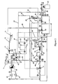
- Figure 2 is a process flowsheet of items of equipment in a two-compartment purification container ("PC") of this invention, in selectively valved fluid connection with plural RO modules which may be operated in either single pass, or double pass operation.
- PC two-compartment purification container
- Figure 3 is a side elevational view of the PC, schematically illustrating the positioning of the various items of equipment so that all items are contained within the PC.
- Figure 4 is a top plan view of the PC to illustrate the accessibility of the items of equipment despite their closely interconnected configuration.
- Figure 5 is an end elevational view looking towards the rear of the PC in the direction 5-5, showing the positioning of the RO vessels and chemical cleaning tank.
- Figure 6 is an end elevational view looking towards the front of the PC in the direction 6-6, showing the positioning of the second pass pump.
- Figure 7 is a rear end elevational view looking towards the front of the PC, showing the positioning of the RO vessels and the first pass process pump.
- Figure 8 is an elevational view looking towards the rear of the PC in the direction 8-8, showing the positioning of the fuel tank outside the main chamber of the PC.
- FIG. 1 An embodiment of a prior art unit in which the high pressure process pump is also used either to flush a RO module periodically, or, to deliver cleaning solution to clean a RO module when it becomes fouled, is schematically illustrated in the flow diagram in Fig 1.
- This unit avoided the use of coagulant, rust inhibitor and citric acid, and permitted back-washing the coarse filter, as the necessity arose.
- the wash water had to be stored in a tank from which it had to be pumped through the filters; and, though a self-contained cleaning system including a cleaning pump to clean the RO modules was avoided, the operation of the process pump had to be interrupted to change over to the cleaning cycle.
- Fig 1 it is seen that raw water is delivered from a feed pump (not shown) through a conduit (or "line") C1, and butterfly valve V1 to a coarse (20 U.S. Standard mesh) filter F1 where relatively large solids are removed.
- the filtered raw water flows through butterfly valve V2 to the suction of a process pump P1.
- the discharge of the pump P1 through line C2 is flowed through three-way valve V3 in line C3, through a 100 ⁇ m "fine” filter F2, then through another three-way valve V4, to two banks of RO modules identified as "ROM" connected in parallel.
- Each bank consists of two ROMs connected in series, the concentrate from the first module being fed to the second module. The concentrates and permeates from each bank are combined.
- the concentrate from the two banks is flowed through check valves V5 and V6, into lines C4 and C5 respectively, the rates of flow from which are combined before being discharged at a concentrate outlet.
- the permeate from the two banks is flowed through lines C6 and C7, the rates of flow from which are combined before being discharged at a permeate outlet which is led to storage.
- the ROMs are flushed by opening solenoid valves S1 and S2 for a short period of time.
- the flow from flushing is carried away by lines C8 and C9 respectively, the rates of flow from which are combined before being discharged at a flush outlet.
- the suction of the pump is placed in flow communication with the solution in a cleaning tank (not shown) , the cartridge filters are removed, and the cleaning solution recirculated through a RO module to be cleaned (the cleaning loop to the cleaning tank is not shown).
- Fig 2 there is schematically illustrated the piping and instrumentation diagram for components mounted in the PC of this invention which is tailored for use to meet specific demands dictated by the ability to transport the PC to a site where the only source water available is contaminated "raw" water, and potable water is required.
- the PC is specifically designed to be loaded onto a truck with a standard pelletized loading system ("PLS") carried on a 10 ton Steyrtruck (Nato Stock #NSN2320-21-901-6002 ECC 126815), referred to herein as a "standard loading means”.
- PLS pelletized loading system
- 10 ton Steyrtruck Nato Stock #NSN2320-21-901-6002 ECC 126815
- Source water typically brackish water or sea water
- the feed pump is preferably a self-priming stainless steel, close-coupled pump with a 2 HP totally enclosed tropicalized motor capable of delivering 40 gpm at 60 ft total discharge head (“TDH").
- the water is pumped from pump 13 to a booster pump 14 where the water is further pressurized, raising the pressure by an additional 50 psi, to add in the range from 40-60 psig, sufficient to flow first through a self-cleaning filter 15 which contains a coarse 200 ⁇ m (micrometers, or microns) screen and a fine 50 ⁇ m screen to remove relatively large suspended solids, then through a pair of 5-15 ⁇ m postfilter cartridges 16 and 16' to remove smaller suspended solids which would damage RO membranes in RO vessels 20 and 21 connected in series.
- a self-cleaning filter 15 which contains a coarse 200 ⁇ m (micrometers, or microns) screen and a fine 50 ⁇ m screen to remove relatively large suspended solids, then through a pair of 5-15 ⁇ m postfilter cartridges 16 and 16' to remove smaller suspended solids which would damage RO membranes in RO vessels 20 and 21 connected in series.
- the filter 15 is preferably a commercially available Filtomat filter having inlet, outlet and drain connections. Most preferred is a Filtomat Model M302L which comprises a cylindrical housing within which cylindrical screens are concentrically disposed in spaced apart relationship to the housing's inner surface. Typically a coarse screen (150 ⁇ m) is disposed above a fine (50 ⁇ m) screen. A dirt scavenger and a hydraulic motor are centrally disposed within the housing so that upon rotation of the scavenger, the inner surfaces of the screens are cleaned. A rinse valve, and a rinse control unit with a pressure-drop switch, are exteriorly disposed relative to the housing.
- the rinse control unit actuates the rinse valve opening it to a drain. Since the drain is at atmospheric pressure, a low pressure path is created through the hydraulic motor and the dirt scavenger, and the filter enters a self-cleaning mode.
- the drain valve as well as a valve which releases water from the bladder tank open, and the cleaning cycle begins, utilizing high flow and high pressure and lasting about 3 to 5 seconds. This low pressure in effect "vacuums" the dirt from the screen at a slot in the dirt scavenger, and sends the dirt through the dirt scavenger, the hydraulic motor and the rinse valve to the drain.
- the high flow rate namely 110 gpm
- the high flow rate is required for no more than 5 secs
- only about 17 gal from the bladder tank is required for discharge, though keeping 20 gal is preferred.
- the two design features namely, the storage of flushing water at over 95 psig in a bladder tank, and, the short duration over which a high flow rate is required, make it possible for the Filtomat to be uniquely adapted for service in the ADROWPU.
- the required energy stored for flushing is derived from high pressure concentrate which is readily available because of the process pump, and this concentrate would have been discharged to drain in normal operation.
- the energy for storing the flushing water, as well as the flushing water itself, are each obtained at no additional cost.
- the postfilter cartridges 16 and 16' are each stainless steel housings that hold four 30'' long 5 ⁇ m cartridges. When the pressure drop across them exceeds 5 psi over that for freshly installed cartridges, the used cartridges are replaced.
- Essentially solids-free water enters a first high pressure pump 17 (first pass pump) and is pumped at a pressure in the range from about 600-650 psig, first to RO vessel 20 where the water is separated into a first permeate stream 22 and a first concentrate stream 23.
- the first concentrate stream 23 is flowed to second RO vessel 21 and is again separated into a second permeate stream 24 and a second concentrate stream 25.
- Each RO vessel 20 and 21 is most preferably fitted with 2 "sea-water" membranes.
- the first and second permeate streams 22 and 24 are of essentially identical purity, and are combined in stream 26. Unless the source water is exceedingly contaminated this stream 26 after chlorination with a controlled injection of chlorine is potable, and is sent to storage outside the PC.
- the chlorine is injected with a chlorine injection pump 28, from a chlorine tank 29.
- a feed water flow rate of 40 gpm about 20 gpm of permeate is produced, the ratio of source water to permeate being 2/1. This ratio is at least 3 times higher than was possible with a prior art unit, irrespective of the great mismatch in overall size of the transportable units used.
- the second pass remains substantially less fouled than the first. Accordingly, the second pass is cleaned first, and the cleaning solution is reused to clean the first pass.
- a portion of second concentrate stream 25 is flowed through conduit 29 to bladder tank 31; and, a portion is flowed through conduit 27 to drain.
- the pressure in the bladder tank 31 may be up to 95 psig so as not to damage the coarse filter.
- Such a filter may be effectively back-flushed with as little as 120 gpm at 100 psig. It will be appreciated, that to back-flush a coarse screen filter effectively the flow of flushing fluid is preferably in a highly turbulent state, or, in "plug flow" as it enters the filter 15.
- the PC When the source water is exceedingly contaminated, the PC is used in its double pass operating mode. In this mode, the combined first pass permeate stream 26 is flowed to the suction of a second high pressure pump (second pass pump) 33 operating in the pressure range from about 500-600 psig, and fed to a single second pass RO vessel 34 containing 2 spiral wound membranes, most preferably "sea-water" membranes.
- the stream 26 is separated into a third permeate stream (second pass permeate) 36 and a third concentrate stream (second pass concentrate) 35.
- the permeate stream 36 as before is chlorinated and stored in a potable water tank.
- the concentrate stream 35 may be returned to the suction of the first high pressure pump 17, or to the second high pressure pump 33, depending upon the level of contaminants in the concentrate stream 35.
- the first pass pump is driven with a motor twice the power of the motor driving the second pass pump.
- FMC triplex plunger pumps are used, the first pass pump being fitted with a 20 HP 1750 rpm TEFC tropicalized motor to deliver 40 gpm, and the second pass pump fitted with a 10 HP 1750 rpm TEFC tropicalized motor to deliver 20 gpm.
- the permeate is diverted to fill the c-i-p ("clean-in-place") tank through conduit 48 if the first pass is used, and 52 if the second pass is used.
- the cleaning cycle is commenced by drawing cleaning solution from the tank 32 through line 41 and the appropriate valve means 42 to the suction side of the booster pump 14.
- the discharge of the pump is diverted through valve means 43 into line 44, and through valve means 45 into line 46.
- the chemical cleaning solution is thus flowed through the first pass modules.
- the permeate portion of the cleaning solution flows through lines 22 and 24 then through valve means 47 into line 48 and is returned, through line 51 to the clean-in-place tank 32.
- the concentrate portion of the cleaning solution is flowed through lines 23, 25, 27 and valve means 49 to line 55 then line 57, and is thus returned to the tank 32. Circulation of the cleaning solution is continued until the RO membranes in the modules are deemed to be adequately clean. When recirculation of the cleaning solution is no longer desired, the solution is diverted by valve 49 to drain.
- the second pass RO module is not as frequently fouled as the first pass modules.
- the second pass module is fouled, it is cleaned, after the unit is shut down, as before, by itself, that is, without at the same time cleaning the first pass modules, so that the condition of the second pass RO module, after cleaning, can be accurately determined.
- the discharge of cleaning solution from the booster pump is led through line 44 and valve means 45 into line 51 and into the RO module 34.
- the permeate from the module 34 flows through line 36, then 52, and is returned to the tank 32 through line 57.
- the concentrate from the module 34 flows through line 35, valve means 53, line 54 and then through line 57 into the tank 32.
- the cleaning solution is circulated through the closed-loop system until the RO module 34 is deemed to be sufficiently cleaned. The cleaning solution is then used to clean the first pass module.
- RO membranes are commonly used to demineralize water (e.g. for pretreating boiler feedwater, and recovering potable water from brackish water or sea water).
- RO membranes provide good service: Filmtec BW-30; Filmtec SW-30; Filmtec SW-30HR; UOP RO membrane; Desal RO membrane; Osmonics RO membrane; Nitto RO membrane.
- valve means whether check valves, three-way valves, or two-way valves, are not given, but they are shown on the flowsheet, along with pulsation dampeners, drains, and instrumentation, to provide a more detailed description of the piping and instrumentation used in the system.
- Conductivity indicators such as a Thorton conductivity meter, measure the level of contaminants in the streams.
- the meter is a dual channel meter which can monitor and display both first and second pass water quality.
- the meter is preferably located on the RO instrumentation panel.
- All electrical power to the PC is supplied by a single diesel generator, and all operations are controlled with a programmable logic controller.
- the output of the generator is 208 volts, 3 phase, 60 Hz.
- a preferred generator is powered by a Deutz air-cooled four cylinder turbo diesel engine and the alternator is a 40 kw Stamford alternator.
- the ADROWPU Since the ADROWPU is to operate without freeze-up at an ambient temperature as low as -40°C, air which is heated by ducting it over the hot cooling fins of the air-cooled diesel engine is used to heat the RO compartment.
- the heated air is ducted through a dividing wall which separates the RO compartment from the generator compartment. During warm weather, the heated air is ducted to the outside environment.
- the self-contained, transportable ADROWPU of this invention comprises plural essential components in combination and in operable fluid relationship with one and another.
- the ADROWPU comprises, an enclosed weather-tight housing having a continuous rectangular base integrally combined with the housing to form a purification container having the overall dimensions of an ISO container, the purification container being adapted to be demountably disposed in a transport means from which the purification container may be deployed without due care, to land on the ground with the base in a horizontal position, and the container right-side-up; an A-frame integrally combined with the base, each including attachment means for deploying the container; hydrocarbon fuel-powered generating means for generating sufficient electricity at a voltage required to operate all components powered by electricity, and storage means for storing enough fuel to operate the generating means for a predetermined period of time; the housing being divided into first and second enclosed compartments separated from one another by a dividing wall, the second compartment having the fuel storage means, and the generating means including electrical control means therefor and a storage battery, housed in the
- FIG 3 there is schematically shown an elevational side view of the ADROWPU indicated generally by reference numeral 60 comprising a housing including first and second fully enclosed compartments 61 and 62, referred to as the 'RO compartment' and the 'generator compartment' respectively, separated by a dividing wall 63.
- Access to the compartment 61 is provided by doors 61' (Fig 4) in the side- and end walls; and the compartment 62 may be opened to the atmosphere by opening doors (not shown) in the side-walls.
- the housing has a rectangular base 64, longer than it is wide, to match the requirements of an ISO container, and the sidewalls 65 and 65' (Fig 7), and common floor 66 of compartments 61 and 62 are continuous and integrally constructed for maximum strength.
- the floor 66 is supported on four I-beams 67 provided with tie-down rings 68 or other attachment means for lifting the ADROWPU. At least the walls and ceiling of the RO compartment are insulated for protection against sub-freezing weather.
- A-frame 69 which provides means for lifting the ADROWPU onto the aforesaid truck.
- the A-frame is also provided with lifting rings (not shown) similar to those (68) shown in Fig 7.
- each of the pumps, the feed pump 13, the booster pump 14, the first pass pump 17, the second pass pump 33, and the chlorine injection pump 28, is floor-mounted on shock-absorber means (not shown).
- the particular shock absorber means used is not narrowly critical provided it will absorb the shocks to which the ROWPU is likely to be subjected, without damage to the equipment.
- shock absorber means floor-mounted on shock absorber means are the following: the chlorine tank 29; the bladder tank 31; the Filtomat coarse filter 15, and the fine prefilters 16 and 16'.
- a power distribution panel 75 and a heater 76 are suspended from the ceiling against the inner surface of the dividing wall 63.
- the diesel generator 72 is floor-mounted on shock absorbing means, and a diesel control panel 74 is suspended from the ceiling.
- FIG 5 there is schematically shown an end elevational view along section 6-6 looking towards the rear of the compartment 61, showing the elevational relationship of the modules, the chlorine tank 29, and the clean-in-place tank 32.
- FIG 6 is an end elevational view along the section 7-7 schematically illustrating the positioning of the components adjacent the dividing wall 63 at the front of the compartment 61.
- the RO modules are stacked in vertical spaced apart relationship, the two first pass modules 20 and 21 above the second pass module 34.
- the control panel and instrument panel are mounted adjacent one side-wall for ease of accessibility, preferably by suspending them from the ceiling of the compartment with appropriate shock-absorbing means.
- Fig 8 there is shown a detail of the fuel tank 73 mounted outside the compartment 61, directly to the floor 66. Mounting the fuel tank in compartment 62 adjacent the generator provides for safety, convenient flow of fuel to the generator, as well as proper distribution of weight.
Landscapes
- Chemical & Material Sciences (AREA)
- Engineering & Computer Science (AREA)
- Water Supply & Treatment (AREA)
- Chemical Kinetics & Catalysis (AREA)
- Nanotechnology (AREA)
- Environmental & Geological Engineering (AREA)
- Hydrology & Water Resources (AREA)
- Life Sciences & Earth Sciences (AREA)
- Organic Chemistry (AREA)
- Health & Medical Sciences (AREA)
- Clinical Laboratory Science (AREA)
- Separation Using Semi-Permeable Membranes (AREA)
- Water Treatment By Sorption (AREA)
Abstract
Description
- This invention relates to an easily transportable unit comprising a container having a base adapted to be picked up and loaded onto or into transport means for transporting the unit, as well as adapted to be unloaded from the transport means, without a requirement of due care. The container is packed with equipment which provides pure water as "permeate" from reverse osmosis ("RO") modules which separate potable water from contaminated water unfit for human use. The specific requirement of the unit is that the RO modules deliver permeate in a relatively small volume/unit time, irrespective of how isolated the environment in which only contaminated fresh water, brackish water, or sea water is to be found.
- As will presently be evident, the maximum dimensions and weight of the unit is specified, as is the wide range of conditions under which it must operate successfully. The problem is to use major components which are readily available and to pack them into the specified dimensions without sacrificing reliability of the unit.
- RO modules in various systems are routinely used to produce high purity water by pumping source water at a pressure above the osmotic pressure of the dissolved substances in the water, through a semipermeable membrane. Permeate passes through the membrane but the contaminants remain in a "concentrate" stream which is discharged. Even to produce only 20 gpm (gallons/minute) of permeate from contaminated water, requires feeding the contaminated water at such high pressure that the mass and weight of the modules housing RO elements with adequate surface area and associated equipment is unexpectedly high. If the Reverse Osmosis Water Purification Unit ("ROWPU") is to be self-contained it must also carry its own tanks for back-flushing (or "back-washing" - the terms are used synonymously) filters and for chemical cleaning solution to clean the RO elements, along with a generator for generating electricity, and related equipment with associated instrumentation.
- In addition to the RO modules and tanks, the equipment packed in the container, referred to as a "purification container" or "PC" for brevity, includes pumps and a combination of coarse and fine prefiltration means, on-board pressurized back-flushing means for a coarse screen filter, and appropriate valving and instrumentation. The modules are connected so that they may be operated in either a single pass or double pass mode, depending upon the quality of the water source, and the amount of the permeate desired.
- More specifically, the RO equipment is specifically directed to fulfill the need of a military personnel unit which requires from about 10 gpm but no more than 20 gpm, typically about 15 gpm, of permeate produced in a totally self-contained PC which is demountably disposed on a truck for transportation, or even carried in an airplane or by a helicopter and air-delivered, so that the PC delivers potable water from whatever source of water which may be available at any location where the PC is delivered. Under conditions of conflict, or in the event of a major accident at a nuclear facility, when water may be contaminated with nuclear, biological and chemical ("NBC" for brevity) warfare agents the equipment is able to deliver potable water at reasonable cost.
- Since in an isolated environment there is no available electrical power, it will be evident that the PC must provide its own, therefore includes a hydrocarbon fuel-powered (diesel fuel) generator. What is less evident is that the PC must be fully assembled and easily operable under difficult conditions, since it is unlikely that skilled personnel will be available to assemble and operate the equipment. In other words, the overriding consideration is that transportability of the PC must be as a single unit with all components preassembled and ready to operate with only rudimentary instructions to an operator.
- The armed services were supplied with a reverse osmosis water purification unit described in an article titled "Reverse Osmosis Development of a High Technology Water Treatment Capability for the Canadian Forces" by Capt M. J. Hauschild in UBIQUE No. 35, pg 32-37, Sept '90. This unit was referred to as an ADROWPU (acronym for Air Deliverable Reverse Osmosis Water Purification Unit), because it was hoped it could be delivered by helicopter. The term "purification container" or PC is used herein substantially synonymously with the term ADROWPU. The components of the system schematically represented in the article, used two banks of RO modules arranged to operate in a double pass mode.
- By "double pass mode" is meant that water to be filtered is flowed through two RO modules, in practice, two banks of modules, in two (first and second) passes. Permeate from the first pass (referred to as "first permeate") is flowed as feed to the second bank to be filtered in a second pass, so as to yield a second permeate different in quality from the first permeate. Thus, if the rejection in the first pass is 80% so that only 20% of the incoming water (to the first bank) is withdrawn as first permeate, this first permeate is then fed to the second bank and again filtered in the second pass. If the rejection in the second pass is the same as that in the first pass, namely 80%, then only 4% of the incoming water (to the first bank) is withdrawn as second permeate from the second pass.
- Details of the ADROWPU referred to in the article are substantially as shown in Figure 1 of the appended drawing. The raw water pump supplied water to a process pump. To remove suspended solids a combination of screen filters (20 mesh and smaller mesh), and cartridge microfilters (100 µm and 50 µm) were used. Other conventional removal of suspended solids, such as by adding coagulant, then flowing through multi-media filters and cartridge microfilters are also effective. This ensured that suspended solids are removed. A solids-free feedwater was fed to the banks of RO modules.
- The last step during normal operation was to add calcium hypochlorite to disinfect the RO permeate so as to maintain a chlorine residual of 5 mg/L. If required, an NBC post treatment with granular activated carbon for chemical warfare agents, and an ion exchange column for nuclear warfare agents is added to the overall package.
- Though the aforementioned ADROWPU delivered the desired permeate at the desired flow rate, it was deemed inadequate for service because of at least two problems. First, operation was interrupted too frequently because the unit was shut down to replace the cartridge filter.
- Other transportable RO module systems have been used by the armed forces. A particular example is described in an article titled "The Army Water Supply Program" by Thomas . Bagwell, Jr., U.S. Army Belvoir Research and Development and Engineering Center, September 1990. This unit was a 600 gal/hr ROWPU in which the components were arranged so that RO modules operating in a double pass mode, produced 10 gpm of permeate from 40 gpm (gals/min) raw water pumped through a multi-media filter. After filtration through the multi-media filters, the water passes through a housing consisting of forty 5 µm cartridge filters. The solids-free feedwater was fed to a bank of four pressure vessels in series, each vessel containing two 6'' (inch) diameter RO membrane elements for a total of 8 elements. Production of permeate had to be interrupted to replace the multimedia filter and to replace the cartridge filters.
- The package was mounted on a 5 ton trailer along with a 30 Kw (kilowatt) generator, and 3 open top collapsible fabric tanks able to hold 3000 gals. Two of the tanks are used to store potable water made, and one is used to collect water for back-washing of the filter media and cleaning of the RO elements with adequately high-pressure pumps. Two raw water pumps supply 30 gal/min to the ROWPU and distribution and back-wash pumps are used when required. Upon unloading the equipment at a chosen site, the components of the ROWPU had to be assembled before being placed in operation.
- The foregoing unit was transportable with difficulty and was therefore limited for use where a very large wheeled vehicle can be driven, or a very large skid can be hauled. Most particularly, and critical to the invention herein, the many components of the armed forces system, and other prior art units, failed to recognize the importance of distributing the components within a housing in such a manner that the masses of the components were substantially symmetrically disposed relative to the center of mass of the container.
- In common with the prior art ADROWPU, the ROWPU screen filters had to be cleaned manually after stopping operation of the unit to make RO permeate. In each case, a source of clean water was required to back-flush the screen filters. In each case, it was a serious drawback with respect to efficient production of RO permeate because permeate was saved to clean the filters.
- The problem of back-flushing the screen filters and chemically cleaning the RO membranes "in place" within the RO vessels is particularly acute when water contaminated by NBC contaminants must be purified, since a source of clean water (such as "tap-water" in a city) is not available, and one can ill afford to use permeate for such a function. Moreover, the use of a back-flushing pump and yet another pump for chemically cleaning the RO membranes added to the size and weight of the equipment in the ROWPU.
- The novel ADROWPU of this invention (still referred to as such because the new and improved unit is air-deliverable) avoids using a back-flushing pump and a separate chemical cleaning pump. Stored permeate is not used to back-flush the screen filters, as was done in the prior art. Further, the screen filters are back-flushed with concentrate from the RO modules which would have been, and is, discarded.
- Most importantly, the screen filters are back-flushed automatically, without stopping production of permeate. This automatic back-flush is accomplished by a unique utilization of a commercially available self-cleaning Filtomat screen equipped with an automatic screen-cleaning means actuated upon being back-flushed. To work efficiently this device is designed to operate with an available supply of at least 110 gals/min at a pressure in excess of 30 psig ( >30 psi) for from 3 to 5 secs.
- Conventionally, several Filtomat screens are used in parallel in a system where the flow of available water is essentially unlimited. When one of the screens becomes fouled, it automatically requires a diversion of flow from the main feed line. This flow is readily supplied because there is no shortage of volume (in excess of 110 gpm is usually available) at above the required pressure.
- In the rare instance where a single Filtomat unit is used, it is not critical to have continuous flow delivered to the system. Under such circumstances, if the feed pressure and flow to the Filtomat is not adequate, the outlet valve on the effluent of the device is automatically closed and not opened until the cleaning cycle is completed.
- In an ADROWPU, since the effluent from the Filtomat is the feed to the process pump, it is critical to maintain the flow of 40 gpm and adequate pressure (15 psig) in the line.
- If, as in a conventional situation, one was to provide 110 gpm for the Filtomat and still maintain a flow of 40 gpm to the ADROWPU unit, one would require a 150 gpm pump. It is mechanically impractical and unsound to constrain a 150 gpm pump solely to use it at its design throughput once every hour (say) for a duration of from 3 to 5 secs. It would be used at the design throughput even less frequently if the raw water to the unit is not too dirty.
- Since the maximum flow in a transportable ADROWPU is 40 gpm, delivered by the feed pump, the conditions of water availability at a site where a ADROWPU unit would operate are far removed from those at a site where such a Filtomat self-cleaning device is conventionally used.
- As will be described in greater detail hereafter, the Filtomat screen can only be used in the ADROWPU in combination with an adequately high pressure storage means capable of delivering at least 110 gpm for a short period of time. It is unexpectedly practical to store the concentrate for back-flushing only because, for back-flushing, this concentrate is to be delivered from the storage means (a bladder tank is used), for only from 3 to 5 seconds at a pressure sufficient to ensure cleaning the fouled screen. Thus, except for storing flushing water in a bladder tank under at least 95 psig pressure (so that at the end of the flushing cycle at least 35 psig remains) the Filtomat could not have been used in an ADROWPU.
- Another improvement in the new ADROWPU is that no permeate is stored, to be made up into a chemical cleaning solution for fouled RO modules. A "clean-in-place" tank is carried in the ADROWPU, but this tank is empty (saving weight) except when the RO modules are being cleaned with permeate to which cleaning chemicals are added.
- Most particularly, the PC of this invention is designed not to use outside sources of water for cleaning of any type, and, as stated hereabove, to position all the components of the PC in a housing so as to secure the relatively heavier components symmetrically about the center of mass of the PC. The method of operating the equipment in the PC, and the effectiveness of each of the combination of system elements in the package, address the inherent deficiencies of the prior art equipment.
- Other deficiencies, such as those discovered during operation in adverse weather, whether frigid or hot, have also been overcome. For example, in sub-zero weather conditions, at ambient temperatures below -15°C, cold enough to freeze water in any of the individual items of equipment in the PC, the prior units used by the army did not function because the equipment was inadequately protected by insulation alone. In the novel PC, heated air, ducted over the hot fins of an air-cooled diesel generator (for the electrical power required to run the PC) provides an unexpectedly effective way of maintaining a desirable temperature within the PC. The heat from the diesel may be supplemented with a conventional heat source such as a 10kW heater, which will come on automatically when the ambient temperature in the PC is below 5°C.
- A novel and surprisingly effective, fully self-contained, easily transportable, reverse osmosis water purification container ("PC") capable of producing no more than about 20 gpm of potable permeate from as little as 40 gpm of brackish water, is constructed by integrating known items of equipment into an ISO (International Standards Organization) container, or equivalent small space, despite including a large, preferably 44 gallon, "bladder" tank and a large, preferably 40 gallon, "cleaning chemicals" tank, each of which tanks permits restoring the efficient operation of screen filters and RO membranes. The surprising effectiveness of the specific combination of individual items of equipment, and their distribution, mounted on shock-absorbing mounting means with the masses of the components and associated piping and controls, in separate first and second compartments, symmetrically about the center of mass of the container in which the components are housed, not only successfully overcomes the deficiencies of prior art units but also allows the PC to have overall dimensions of an ISO container (5.5m long x 2.1m wide x 1.7m high) so that it can be pelletized for ruggedized handling, capable of withstanding a shock of 10 Gs.
- It has been discovered that a combination of a relatively coarse screen automatically back-flushable filter having openings no greater than 300 µm, preferably 200 µm, and, a fine filter, preferably comprising a 50µm screen filter disposed upstream of, and immediately prior to plural 5µm-15µm cartridge filters, effectively removes screen-plugging solids before they reach the cartridge filters; this avoids the use of coagulants and multi-media filters, and allows the use of disposable cartridge filters, so that only the coarse screen filter needs to be back-flushed automatically. This latter operation is accomplished by "pumpless back-flushing" with concentrate stored in a bladder tank, without manual intervention by the operator. The coarse screen filter is therefore termed a "self-cleaning" filter.
- It has also been discovered that only three RO pressure vessels ("modules"), each equipped with only 2 spiral wound RO membranes, are necessary to provide a double-pass operation to purify brackish water and yield nearly 11 gpm of permeate, provided two first-pass and one second-pass RO modules are connected as follows: concentrate from one first pass module is fed to a second first pass module, and the permeate from both first pass modules is fed to a second pass pump; normally brackish water may be purified in a single pass yielding about 20 gpm of permeate with a 40 gpm brackish water supply; in double pass operation the yield of permeate is about 11 gpm; and, the PC is operable at ambient temperatures in the range from -40°C to 40°C. In all instances, potable permeate meets the standard of NATO STANAG 2136 QSTAG 245.
- It is therefore a general object of this invention to provide a combination of coarse and fine filtration means to remove suspended solids, an automatic self-cleaning means for a back-flushable coarse screen filter means, and, only spiral flow RO modules arranged for first and second pass operation, preferably only three RO modules. Two modules in a first bank are in series in a first pass mode, the concentrate from the first being used as feed to the second. A single module in the second pass is connected to have permeate from both modules in the first bank directly fed into the second pass process pump which feeds the permeate directly into the second pass module, eliminating any chance to introduce contaminants in the water.
- It is a specific object of this invention to provide a water purification system to deliver no more than 20 gpm of RO water permeate, packaged in a PC in which only about 40 gals of cleaning solution is made up with permeate from either the first or second pass RO vessels in the PC. Conventional chemicals are used to make up a "cleaning solution" for the RO membranes. This cleaning solution is pumped through one pass of modules at a time using the booster pump (used to repressurize feed water into the system), thus avoiding the use of an additional cleaning pump.
- It is another specific object of this invention to provide a PC which is not only easily ground-transportable but also air-transportable by virtue of the disposition of the components of the PC substantially symmetrically about the vertical planes intersecting at the physical center of a rectangular box-like container, and also substantially symmetrically about the center of mass of the PC, so that the PC may be unloaded from above the ground to land on its base, deposited horizontally and right-side up, that is, the container remains oriented substantially symmetrically about a vertical plane, for example, even when it is lowered from the air by a helicopter.
- It is still another specific object of this invention to provide a process for delivering no more than 20 gpm of reverse osmosis permeate comprising, providing a PC no larger than an ISO container constructed to accommodate, fixedly disposed therein, all equipment including instrumentation to control operation thereof; filtering brackish water through a combination of a coarse screen filter having openings of 200 µm, and a fine filter having openings no larger than 100 µm to produce filtered water, automatically back-flushing the coarse filter when it is sufficiently fouled to provide an unacceptably high pressure drop, flowing the filtered water through at least one pass of RO modules, recovering the RO permeate, and storing a portion of RO concentrate under elevated pressure above that required to back-flush the coarse filter, the amount of concentrate stored being sufficient to back-flush the coarse filter; and, periodically, the frequency depending upon the quality of brackish water, replacing the fine filter means, "on the fly" without interrupting production of permeate.
- It is a further specific object of this invention to provide a process for cleaning a fouled reverse osmosis membrane used in either a first pass operation or a second pass operation of a RO subsystem in an air-deliverable reverse osmosis purification unit, comprising, diverting permeate to a cleaning tank, adding appropriate chemicals to diverted permeate in the tank to form a cleaning solution, flowing the cleaning solution to the suction side of the booster pump, and diverting the discharge of cleaning solution to the fouled membrane to be cleaned.
- The foregoing and additional objects and advantages of the invention will best be understood by reference to the following detailed description, accompanied with schematic illustrations of preferred embodiments of the invention, in which illustrations like reference numerals refer to like elements, and in which:
- Figure 1 is a diagrammatic illustration of an embodiment of a prior ROWPU unit disclosed in a U.S. Army brochure, for producing RO water from brackish water using a RO subsystem, in addition to other means required, referred to hereinabove, which unit was modified in a ADROWPU unit disclosed in the Canadian publication UBIQUE, for a double pass operation.
- Figure 2 is a process flowsheet of items of equipment in a two-compartment purification container ("PC") of this invention, in selectively valved fluid connection with plural RO modules which may be operated in either single pass, or double pass operation.
- Figure 3 is a side elevational view of the PC, schematically illustrating the positioning of the various items of equipment so that all items are contained within the PC.
- Figure 4 is a top plan view of the PC to illustrate the accessibility of the items of equipment despite their closely interconnected configuration.
- Figure 5 is an end elevational view looking towards the rear of the PC in the direction 5-5, showing the positioning of the RO vessels and chemical cleaning tank.
- Figure 6 is an end elevational view looking towards the front of the PC in the direction 6-6, showing the positioning of the second pass pump.
- Figure 7 is a rear end elevational view looking towards the front of the PC, showing the positioning of the RO vessels and the first pass process pump.
- Figure 8 is an elevational view looking towards the rear of the PC in the direction 8-8, showing the positioning of the fuel tank outside the main chamber of the PC.
- In a scale-up of the prior 600 gals/hr ROWPU to 3000 gals/hr, also described in the aforementioned brochure by Bagwell, Jr., cyclone separators were suggested prior to flowing raw water to basket filters, followed by a multimedia filter and cartridge filters. A coagulant and a scale inhibitor were injected into the raw water supply pumped to the multi-media filter. In either version of the process it was not possible to clean either the filters or the RO elements in place. A double pass operation required storing, then reusing the permeate from the first pass.
- An embodiment of a prior art unit in which the high pressure process pump is also used either to flush a RO module periodically, or, to deliver cleaning solution to clean a RO module when it becomes fouled, is schematically illustrated in the flow diagram in Fig 1. This unit avoided the use of coagulant, rust inhibitor and citric acid, and permitted back-washing the coarse filter, as the necessity arose. However, the wash water had to be stored in a tank from which it had to be pumped through the filters; and, though a self-contained cleaning system including a cleaning pump to clean the RO modules was avoided, the operation of the process pump had to be interrupted to change over to the cleaning cycle.
- Referring in greater detail to the system shown in Fig 1 it is seen that raw water is delivered from a feed pump (not shown) through a conduit (or "line") C1, and butterfly valve V1 to a coarse (20 U.S. Standard mesh) filter F1 where relatively large solids are removed. The filtered raw water flows through butterfly valve V2 to the suction of a process pump P1. The discharge of the pump P1 through line C2 is flowed through three-way valve V3 in line C3, through a 100µm "fine" filter F2, then through another three-way valve V4, to two banks of RO modules identified as "ROM" connected in parallel. Each bank consists of two ROMs connected in series, the concentrate from the first module being fed to the second module. The concentrates and permeates from each bank are combined.
- The concentrate from the two banks is flowed through check valves V5 and V6, into lines C4 and C5 respectively, the rates of flow from which are combined before being discharged at a concentrate outlet. The permeate from the two banks is flowed through lines C6 and C7, the rates of flow from which are combined before being discharged at a permeate outlet which is led to storage.
- At preset intervals of time, the ROMs are flushed by opening solenoid valves S1 and S2 for a short period of time. The flow from flushing is carried away by lines C8 and C9 respectively, the rates of flow from which are combined before being discharged at a flush outlet. For cleaning, the suction of the pump is placed in flow communication with the solution in a cleaning tank (not shown) , the cartridge filters are removed, and the cleaning solution recirculated through a RO module to be cleaned (the cleaning loop to the cleaning tank is not shown).
- The foregoing unit which was conventionally constructed relied upon an outside source of water for back-washing the coarse filter F1 and the fine filter F2. As shown in Fig 1, cleaning the filter F1 was done periodically by shutting down the unit, and connecting the valves V9 and V10 to the source of wash water. In an analogous manner, F2 was washed by connecting valves V3 and V4 to the source of wash water. Pressure indicating gauges identified as PI (nos. 01, 03, 04, 05, 06, 07 an 08) monitor the pressure conditions in the respective lines, and low pressure sensing switch PSL01 protects the process pump.
- The above system was modified in the ADROWPU referred to in the Canadian publication, in a conventional manner to allow for removal of permeate from single pass operation. In actual operation the filters unit, particularly the coarse filter, plugged too frequently, requiring frequent washing with clean water. For reasons given herebelow, there was no reason to store concentrate to wash the filter.
- Referring to Fig 2, there is schematically illustrated the piping and instrumentation diagram for components mounted in the PC of this invention which is tailored for use to meet specific demands dictated by the ability to transport the PC to a site where the only source water available is contaminated "raw" water, and potable water is required. The PC is specifically designed to be loaded onto a truck with a standard pelletized loading system ("PLS") carried on a 10 ton Steyrtruck (Nato Stock #NSN2320-21-901-6002 ECC 126815), referred to herein as a "standard loading means".
- Source water, typically brackish water or sea water, is drawn through a
strainer 11 on asuction hose 12 by afeed pump 13. The feed pump is preferably a self-priming stainless steel, close-coupled pump with a 2 HP totally enclosed tropicalized motor capable of delivering 40 gpm at 60 ft total discharge head ("TDH"). The water is pumped frompump 13 to abooster pump 14 where the water is further pressurized, raising the pressure by an additional 50 psi, to add in the range from 40-60 psig, sufficient to flow first through a self-cleaningfilter 15 which contains a coarse 200µm (micrometers, or microns) screen and a fine 50µm screen to remove relatively large suspended solids, then through a pair of 5-15µm postfilter cartridges 16 and 16' to remove smaller suspended solids which would damage RO membranes inRO vessels - The
filter 15 is preferably a commercially available Filtomat filter having inlet, outlet and drain connections. Most preferred is a Filtomat Model M302L which comprises a cylindrical housing within which cylindrical screens are concentrically disposed in spaced apart relationship to the housing's inner surface. Typically a coarse screen (150 µm) is disposed above a fine (50 µm) screen. A dirt scavenger and a hydraulic motor are centrally disposed within the housing so that upon rotation of the scavenger, the inner surfaces of the screens are cleaned. A rinse valve, and a rinse control unit with a pressure-drop switch, are exteriorly disposed relative to the housing. When the pressure drop across the fine screen reaches a preset level, say about 7 psi, the rinse control unit actuates the rinse valve opening it to a drain. Since the drain is at atmospheric pressure, a low pressure path is created through the hydraulic motor and the dirt scavenger, and the filter enters a self-cleaning mode. The drain valve as well as a valve which releases water from the bladder tank open, and the cleaning cycle begins, utilizing high flow and high pressure and lasting about 3 to 5 seconds. This low pressure in effect "vacuums" the dirt from the screen at a slot in the dirt scavenger, and sends the dirt through the dirt scavenger, the hydraulic motor and the rinse valve to the drain. Flow of the water out of the unit causes the hydraulic motor to spin the dirt scavenger. As the screen is cleaned the pressure drop decreases and when essentially zero, the pressure-drop switch closes the rinse valve. The rinse cycle last about 5 secs and uses about 12 gal of water without interrupting the flow. When the cleaning cycle is complete, the drain valve and the bladder tank are automatically closed and the bladder tank is recharged for the next cleaning. - Because the high flow rate, namely 110 gpm, is required for no more than 5 secs, only about 17 gal from the bladder tank is required for discharge, though keeping 20 gal is preferred. The two design features, namely, the storage of flushing water at over 95 psig in a bladder tank, and, the short duration over which a high flow rate is required, make it possible for the Filtomat to be uniquely adapted for service in the ADROWPU.
- As an added benefit, the required energy stored for flushing is derived from high pressure concentrate which is readily available because of the process pump, and this concentrate would have been discharged to drain in normal operation. In other words, the energy for storing the flushing water, as well as the flushing water itself, are each obtained at no additional cost.
- The
postfilter cartridges 16 and 16' are each stainless steel housings that hold four 30'' long 5µm cartridges. When the pressure drop across them exceeds 5 psi over that for freshly installed cartridges, the used cartridges are replaced. - Essentially solids-free water enters a first high pressure pump 17 (first pass pump) and is pumped at a pressure in the range from about 600-650 psig, first to
RO vessel 20 where the water is separated into afirst permeate stream 22 and afirst concentrate stream 23. Thefirst concentrate stream 23 is flowed tosecond RO vessel 21 and is again separated into asecond permeate stream 24 and asecond concentrate stream 25. EachRO vessel - The first and second permeate streams 22 and 24 are of essentially identical purity, and are combined in
stream 26. Unless the source water is exceedingly contaminated thisstream 26 after chlorination with a controlled injection of chlorine is potable, and is sent to storage outside the PC. The chlorine is injected with achlorine injection pump 28, from achlorine tank 29. In a single pass operation, with a feed water flow rate of 40 gpm, about 20 gpm of permeate is produced, the ratio of source water to permeate being 2/1. This ratio is at least 3 times higher than was possible with a prior art unit, irrespective of the great mismatch in overall size of the transportable units used. Typically, when the double pass mode is used, the second pass remains substantially less fouled than the first. Accordingly, the second pass is cleaned first, and the cleaning solution is reused to clean the first pass. - A portion of
second concentrate stream 25 is flowed throughconduit 29 tobladder tank 31; and, a portion is flowed throughconduit 27 to drain. The pressure in thebladder tank 31 may be up to 95 psig so as not to damage the coarse filter. Such a filter may be effectively back-flushed with as little as 120 gpm at 100 psig. It will be appreciated, that to back-flush a coarse screen filter effectively the flow of flushing fluid is preferably in a highly turbulent state, or, in "plug flow" as it enters thefilter 15. - When the source water is exceedingly contaminated, the PC is used in its double pass operating mode. In this mode, the combined first
pass permeate stream 26 is flowed to the suction of a second high pressure pump (second pass pump) 33 operating in the pressure range from about 500-600 psig, and fed to a single secondpass RO vessel 34 containing 2 spiral wound membranes, most preferably "sea-water" membranes. Thestream 26 is separated into a third permeate stream (second pass permeate) 36 and a third concentrate stream (second pass concentrate) 35. Thepermeate stream 36, as before is chlorinated and stored in a potable water tank. - The
concentrate stream 35 may be returned to the suction of the firsthigh pressure pump 17, or to the secondhigh pressure pump 33, depending upon the level of contaminants in theconcentrate stream 35. - Since the high pressure pump for the first pass is for twice the flow rate as the second pass pump, the first pass pump is driven with a motor twice the power of the motor driving the second pass pump. Preferably FMC triplex plunger pumps are used, the first pass pump being fitted with a 20 HP 1750 rpm TEFC tropicalized motor to deliver 40 gpm, and the second pass pump fitted with a 10 HP 1750 rpm TEFC tropicalized motor to deliver 20 gpm.
- When the first pass RO modules are fouled sufficiently to require chemical cleaning, before the pumps are shut off, the permeate is diverted to fill the c-i-p ("clean-in-place") tank through conduit 48 if the first pass is used, and 52 if the second pass is used. The cleaning cycle is commenced by drawing cleaning solution from the
tank 32 through line 41 and the appropriate valve means 42 to the suction side of thebooster pump 14. The discharge of the pump is diverted through valve means 43 intoline 44, and through valve means 45 intoline 46. - The chemical cleaning solution is thus flowed through the first pass modules. The permeate portion of the cleaning solution flows through
lines line 51 to the clean-in-place tank 32. The concentrate portion of the cleaning solution is flowed throughlines line 55 thenline 57, and is thus returned to thetank 32. Circulation of the cleaning solution is continued until the RO membranes in the modules are deemed to be adequately clean. When recirculation of the cleaning solution is no longer desired, the solution is diverted byvalve 49 to drain. - Typically the second pass RO module is not as frequently fouled as the first pass modules. When the second pass module is fouled, it is cleaned, after the unit is shut down, as before, by itself, that is, without at the same time cleaning the first pass modules, so that the condition of the second pass RO module, after cleaning, can be accurately determined.
- To clean the second
pass RO module 34, the discharge of cleaning solution from the booster pump is led throughline 44 and valve means 45 intoline 51 and into theRO module 34. The permeate from themodule 34 flows throughline 36, then 52, and is returned to thetank 32 throughline 57. The concentrate from themodule 34 flows throughline 35, valve means 53,line 54 and then throughline 57 into thetank 32. As before, the cleaning solution is circulated through the closed-loop system until theRO module 34 is deemed to be sufficiently cleaned. The cleaning solution is then used to clean the first pass module. - The requirement of high pressure delivered by the high pressure pump is required because an RO membrane is semipermeable and requires the aqueous feed to be pumped to it at a pressure above the osmotic pressure of the dissolved substances in the water. Because an RO membrane can effectively remove low mol wt molecules <150 Daltons, and also ions from water, RO membranes are commonly used to demineralize water (e.g. for pretreating boiler feedwater, and recovering potable water from brackish water or sea water).
- The following RO membranes provide good service: Filmtec BW-30; Filmtec SW-30; Filmtec SW-30HR; UOP RO membrane; Desal RO membrane; Osmonics RO membrane; Nitto RO membrane.
- In the aforementioned description of the process flow, details of the valve means, whether check valves, three-way valves, or two-way valves, are not given, but they are shown on the flowsheet, along with pulsation dampeners, drains, and instrumentation, to provide a more detailed description of the piping and instrumentation used in the system.
- In the drawing, the code for the reference characters used in the drawing is as follows:
- AH
- alarm high
- CE
- conductivity element
- FI
- flow indicator
- FQC
- flow totalling controller
- I
- interlock (electrical)
- M
- motor
- PD
- pulsation dampener
- PI
- pressure indicator
- PSL
- pressure switch low
- S
- solenoid
- PRV
- pressure regulating valve
- HVA
- hydraulic valve assembly
- Conductivity indicators, such as a Thorton conductivity meter, measure the level of contaminants in the streams. The meter is a dual channel meter which can monitor and display both first and second pass water quality. The meter is preferably located on the RO instrumentation panel.
- All electrical power to the PC is supplied by a single diesel generator, and all operations are controlled with a programmable logic controller. The output of the generator is 208 volts, 3 phase, 60 Hz. A preferred generator is powered by a Deutz air-cooled four cylinder turbo diesel engine and the alternator is a 40 kw Stamford alternator.
- Since the ADROWPU is to operate without freeze-up at an ambient temperature as low as -40°C, air which is heated by ducting it over the hot cooling fins of the air-cooled diesel engine is used to heat the RO compartment. The heated air is ducted through a dividing wall which separates the RO compartment from the generator compartment. During warm weather, the heated air is ducted to the outside environment.
- It will now be evident that the self-contained, transportable ADROWPU of this invention comprises plural essential components in combination and in operable fluid relationship with one and another. The ADROWPU comprises, an enclosed weather-tight housing having a continuous rectangular base integrally combined with the housing to form a purification container having the overall dimensions of an ISO container, the purification container being adapted to be demountably disposed in a transport means from which the purification container may be deployed without due care, to land on the ground with the base in a horizontal position, and the container right-side-up; an A-frame integrally combined with the base, each including attachment means for deploying the container; hydrocarbon fuel-powered generating means for generating sufficient electricity at a voltage required to operate all components powered by electricity, and storage means for storing enough fuel to operate the generating means for a predetermined period of time; the housing being divided into first and second enclosed compartments separated from one another by a dividing wall, the second compartment having the fuel storage means, and the generating means including electrical control means therefor and a storage battery, housed in the second compartment; the first compartment having housed therein substantially all remaining components for purifying raw contaminated water, the components including, a first pass reverse osmosis module and a second pass reverse osmosis module; a feed pump, a booster pump, first pass and second pass process pumps, and a chlorine injection pump; first pass and second pass reverse osmosis modules having reverse osmosis elements disposed therein; coarse filter means and fine filter means; a bladder tank having a capacity of at least 17 gal, preferably no more than 50 gal; a "clean-in-place" cleaning tank having a capacity of at least 30 gal, preferably no more than 50 gal; and, control means to operate said components to deliver no more than 20 gpm of permeate in a single pass operation; the first and second compartments having equipment therein demountably secured to the base and interior surfaces of the compartments with shock-absorbing means, the equipment being essentially symmetrically distributed about the center of mass of the container, whereby the container may be unloaded from above the ground and land thereon, base first, and the container remain oriented in a substantially vertical position.
- The positioning of the various items of equipment so as to meet the critical spatial requirement of an ISO unit, yet be substantially symmetrically disposed about the center of mass of the PC, will be better appreciated by reference to the Figs 3-8.
- Referring first to Fig 3, there is schematically shown an elevational side view of the ADROWPU indicated generally by
reference numeral 60 comprising a housing including first and second fullyenclosed compartments wall 63. Access to thecompartment 61 is provided by doors 61' (Fig 4) in the side- and end walls; and thecompartment 62 may be opened to the atmosphere by opening doors (not shown) in the side-walls. The housing has arectangular base 64, longer than it is wide, to match the requirements of an ISO container, and thesidewalls 65 and 65' (Fig 7), andcommon floor 66 ofcompartments floor 66 is supported on four I-beams 67 provided with tie-down rings 68 or other attachment means for lifting the ADROWPU. At least the walls and ceiling of the RO compartment are insulated for protection against sub-freezing weather. - One end (front) of the
base 64 is provided with an A-frame 69 which provides means for lifting the ADROWPU onto the aforesaid truck. The A-frame is also provided with lifting rings (not shown) similar to those (68) shown in Fig 7. - Referring now to
compartment 61, and specifically to Figs 3 and 4, it is seen that the pumps are mounted on the floor. Each of the pumps, thefeed pump 13, thebooster pump 14, thefirst pass pump 17, thesecond pass pump 33, and thechlorine injection pump 28, is floor-mounted on shock-absorber means (not shown). The particular shock absorber means used is not narrowly critical provided it will absorb the shocks to which the ROWPU is likely to be subjected, without damage to the equipment. - Also floor-mounted on shock absorber means are the following: the
chlorine tank 29; thebladder tank 31; the Filtomatcoarse filter 15, and the fine prefilters 16 and 16'. Apower distribution panel 75 and aheater 76 are suspended from the ceiling against the inner surface of the dividingwall 63. - In
compartment 62, thediesel generator 72 is floor-mounted on shock absorbing means, and adiesel control panel 74 is suspended from the ceiling. - It will now be evident that the weight of the components is distributed in each of the compartments with the specific purpose of maintaining the center of mass of the ADROWPU at the intersection of the diagonals drawn from the four corners of the base of the
housing 60. This requirement of substantial symmetry is critical to provide ease of transportability and deployment of the ADROWPU. - Referring to Fig 5 there is schematically shown an end elevational view along section 6-6 looking towards the rear of the
compartment 61, showing the elevational relationship of the modules, thechlorine tank 29, and the clean-in-place tank 32. - Referring to Fig 6 is an end elevational view along the section 7-7 schematically illustrating the positioning of the components adjacent the dividing
wall 63 at the front of thecompartment 61. - As indicated in the schematic end elevational view shown in Fig 7, the RO modules are stacked in vertical spaced apart relationship, the two
first pass modules second pass module 34. The control panel and instrument panel are mounted adjacent one side-wall for ease of accessibility, preferably by suspending them from the ceiling of the compartment with appropriate shock-absorbing means. - Referring to Fig 8 there is shown a detail of the
fuel tank 73 mounted outside thecompartment 61, directly to thefloor 66. Mounting the fuel tank incompartment 62 adjacent the generator provides for safety, convenient flow of fuel to the generator, as well as proper distribution of weight. - Having thus provided a general discussion, and specific illustrations of the best mode of constructing a purification container to provide a specific design quantity of permeate under essentially any conditions locate adjacent any contaminated source of water, all equipment being packaged within the confines of an ISO container, or equivalent thereof, and having described how the novel ADROWPU's programmed operation allows an unskilled person to use it, it is to be understood that no undue restrictions are to be imposed by reason thereof except as provided by the following claims.
Claims (8)
- A self-contained, transportable reverse osmosis water purification unit having a throughput of no more than about 20 gpm (about 88 l/m) of permeate in a single pass operation, said unit comprising,
an enclosed weather-tight housing having a continuous base integrally combined with said housing to form a purification container having the overall dimensions of an ISO container, said purification container being adapted to be demountably disposed in a transport means from which said purification container may be deployed without due care, to land on the ground in a horizontal position, right-side-up;
an A-frame integrally combined with said base, each including attachment means for deploying said container;
hydrocarbon fuel-powered generating means for generating sufficient electricity at a voltage required to operate all components powered by electricity, and storage means for storing enough fuel to operate said generating means for a predetermined period of time;
said housing being divided into first and second enclosed compartments separated from one another by a dividing wall, said second compartment having said fuel storage means, and said generating means including electrical control means therefor and a storage battery, housed in said second compartment;
said first compartment having housed therein substantially all remaining components for purifying raw contaminated water, said components including,
a first pass reverse osmosis module and a second pass reverse osmosis module; a feed pump, a booster pump, first pass and second pass process pumps, and a chlorine injection pump; first pass and second pass reverse osmosis modules having reverse osmosis elements disposed therein; coarse filter means and fine filter means; a bladder tank having a capacity of at least 17 gal (about 75 litre); a cleaning tank having a capacity of at least 30 gal (about 132 litre); and, control means to operate said components to deliver no more than 20 gpm (88 l/m) of permeate in a single pass operation;
said first and second compartments having equipment therein demountably secured to said base and interior surfaces of said compartments with shock-absorbing means, said equipment being essentially symmetrically distributed about the center of mass of said container,
whereby said container may be unloaded from a supporting surface above the ground and land thereon, base first, and remain oriented in a substantially vertical position. - The purification unit of claim 1 wherein said coarse filter means includes automatic self-cleaning means adapted to back-wash said coarse filter means without interruption of flow of raw water to said fine filter means, and without utilizing a source of water other than stored concentrate.
- The purification unit of claim 2 wherein said first pass module comprises plural modules connected in series, so as to flow concentrate from the first as feed to the second, the permeates and concentrates from said plural modules being respectively combined; and, said second pass comprises a single second pass module connected in selective permeate-flow-communication with said first pass modules so as to flow said permeates as feed to said second pass module.
- The purification unit of claim 3 wherein said self-cleaning means is in selective fluid communication with concentrate stored in said bladder tank, and said concentrate is pumplessly delivered to said self-cleaning means.
- The purification unit of claim 4 including conduit and valving means to chemically clean said first pass modules and said second pass module, separately, without removing said reverse osmosis elements from within said modules, and without utilizing a source of water other than permeate.
- The purification unit of claim 1 wherein said fine filter comprises a combination of a 50µm screen filter disposed upstream plural 5µm-15µm cartridge filters.
- A process for delivering no more than 20 gpm (88 l/m) of permeate from reverse osmosis modules housed in a transportable container constructed to have fixedly disposed therein all equipment including instrumentation to control operation thereof, said process comprising, providing a purification container no larger than an ISO container; filtering brackish water through a combination of a coarse screen filter having openings no larger than 300 µm, and a fine filter having openings no larger than 100 µm to produce filtered water; automatically back-flushing said coarse filter when it is sufficiently fouled to provide a pressure drop sufficiently high to indicate an unacceptable constriction of flow; flowing said filtered water through at least one pass of reverse osmosis modules; recovering said permeate; and, storing a portion of concentrate from at least one of said reverse osmosis modules, under elevated pressure above that required to back-flush said coarse filter, the amount of concentrate stored being sufficient to back-flush said coarse filter; and, periodically replacing said fine filter means without interrupting production of permeate.
- A process for cleaning a fouled reverse osmosis membrane used in either a first pass operation or a second pass operation of a reverse osmosis subsystem in an air-deliverable reverse osmosis purification unit, comprising, diverting permeate to a cleaning tank; adding appropriate chemicals to diverted permeate in the tank to form a cleaning solution; flowing said cleaning solution to the suction side of said booster pump; and, diverting said cleaning solution discharged by said booster pump to a fouled membrane to be cleaned.
Applications Claiming Priority (2)
| Application Number | Priority Date | Filing Date | Title |
|---|---|---|---|
| US07/959,086 US5244579A (en) | 1992-10-09 | 1992-10-09 | Transportable reverse osmosis water purification unit |
| US959086 | 1992-10-09 |
Publications (3)
| Publication Number | Publication Date |
|---|---|
| EP0592372A2 true EP0592372A2 (en) | 1994-04-13 |
| EP0592372A3 EP0592372A3 (en) | 1994-05-18 |
| EP0592372B1 EP0592372B1 (en) | 1998-12-02 |
Family
ID=25501657
Family Applications (1)
| Application Number | Title | Priority Date | Filing Date |
|---|---|---|---|
| EP93810709A Expired - Lifetime EP0592372B1 (en) | 1992-10-09 | 1993-10-08 | Transportable reverse osmosis water purification unit |
Country Status (4)
| Country | Link |
|---|---|
| US (1) | US5244579A (en) |
| EP (1) | EP0592372B1 (en) |
| CA (1) | CA2108023C (en) |
| DE (2) | DE9321520U1 (en) |
Cited By (6)
| Publication number | Priority date | Publication date | Assignee | Title |
|---|---|---|---|---|
| WO1996041674A1 (en) * | 1995-06-08 | 1996-12-27 | Schael Wilfried | Method and device for treating water according to the principle of reversed osmosis |
| EP1426097A1 (en) * | 2002-12-04 | 2004-06-09 | Mediscan GmbH & Co. KG | Device and method for separating a solvent from a solution |
| WO2014097179A1 (en) * | 2012-12-21 | 2014-06-26 | Degremont | Water treatment plant, in particular for seawater desalination |
| EP2788104A4 (en) * | 2012-02-13 | 2015-10-07 | Langh Tech Ab Oy | Method for treating impurities contained in exhaust gases of ships, ship with exhaust gas scrubber, and purification unit |
| EP2786797A4 (en) * | 2010-01-20 | 2016-03-30 | Aqua Life Spolka Z Ograniczona Odpowiedzialnoscia Spolka Komandytowa | Reverse osmosis water distilling module (variant embodiments) |
| DE102023107305A1 (en) | 2023-03-23 | 2024-09-26 | Kärcher Futuretech GmbH | MOBILE WATER TREATMENT PLANT TO PRODUCE DRINKING WATER IN A DISASTER AREA |
Families Citing this family (103)
| Publication number | Priority date | Publication date | Assignee | Title |
|---|---|---|---|---|
| AU2251495A (en) * | 1994-05-02 | 1995-11-29 | Master Flo Technology Inc. | Reverse osmosis filtration system |
| DE4446211C1 (en) * | 1994-12-23 | 1995-10-26 | Bundesrep Deutschland | Process and plant for the treatment of water poisoned by warfare agents |
| DE19516969A1 (en) * | 1995-05-12 | 1996-11-14 | Bernhard Lenz | Plant and method for cleaning vapor condensates from wort boiling during beer production |
| WO1997029995A1 (en) * | 1996-02-12 | 1997-08-21 | Aqua System A/S | Plant for production of drinking water from unfiltered water |
| US5743925A (en) * | 1996-04-10 | 1998-04-28 | The United States Of America As Represented By The Department Of Energy | Compact cyclone filter train for radiological and hazardous environments |
| US5788858A (en) * | 1996-05-03 | 1998-08-04 | Terra Group, Inc. | Mobile water purification unit with modular dechlorination input stage |
| US5776339A (en) * | 1996-07-29 | 1998-07-07 | Samsung Electronics Co., Ltd. | Water purifier having purified water storage tank and valve for discharging purified water before reaching the tank |
| US6120688A (en) * | 1997-02-25 | 2000-09-19 | Zenon Environmental, Inc. | Portable reverse osmosis unit for producing drinking water |
| US5972216A (en) * | 1997-10-24 | 1999-10-26 | Terra Group, Inc. | Portable multi-functional modular water filtration unit |
| US6099735A (en) * | 1998-06-04 | 2000-08-08 | Kelada; Maher I. | Counter top reverse osmosis water purification system |
| US6228255B1 (en) | 1998-07-24 | 2001-05-08 | Dialysis Systems, Inc. | Portable water treatment facility |
| US5997737A (en) * | 1998-07-31 | 1999-12-07 | Moreno International, L.L.C. | Portable skid mounted desalination apparatus |
| US6736966B2 (en) | 1999-05-25 | 2004-05-18 | Miox Corporation | Portable water disinfection system |
| US6558537B1 (en) | 1999-05-25 | 2003-05-06 | Miox Corporation | Portable hydration system |
| US7297268B2 (en) | 1999-05-25 | 2007-11-20 | Miox Corporation | Dual head pump driven filtration system |
| US7244357B2 (en) * | 1999-05-25 | 2007-07-17 | Miox Corporation | Pumps for filtration systems |
| US6709599B1 (en) * | 1999-10-27 | 2004-03-23 | Rwe Nukem Corporation | Waste water treatment system with slip stream |
| US6251279B1 (en) | 1999-12-09 | 2001-06-26 | Dialysis Systems, Inc. | Heat disinfection of a water supply |
| BR0209036A (en) * | 2001-04-18 | 2007-01-02 | Buddy Don Gray | Method and apparatus for a recirculating tangential separation system |
| US7005075B2 (en) * | 2001-07-16 | 2006-02-28 | Miox Corporation | Gas drive electrolytic cell |
| US7008523B2 (en) * | 2001-07-16 | 2006-03-07 | Miox Corporation | Electrolytic cell for surface and point of use disinfection |
| NL1018569C2 (en) * | 2001-07-17 | 2003-01-23 | Ceap B V | Mobile power plant. |
| US6579447B2 (en) * | 2001-07-25 | 2003-06-17 | Lancer Partnership, Ltd. | Self-cleaning pre-filter system |
| WO2003031341A1 (en) * | 2001-10-11 | 2003-04-17 | Robert Niederer | Mobile cube for the production of energy and the purification of water by reverse osmosis and similar techniques |
| US6694739B2 (en) | 2001-10-12 | 2004-02-24 | Mesosystems Technology, Inc. | Modular water heater |
| KR100421052B1 (en) * | 2002-01-24 | 2004-03-04 | 삼성전자주식회사 | Apparatus for manufacturing deionized water and using method thereof |
| US7230819B2 (en) | 2002-09-13 | 2007-06-12 | Skybuilt Power, Llc | Mobile power system |
| US7501061B2 (en) * | 2002-10-23 | 2009-03-10 | Siemens Water Technologies Holding Corp. | Production of water for injection using reverse osmosis |
| US20030173296A1 (en) * | 2003-04-14 | 2003-09-18 | Costa Lawrence C | High recovery reverse osmosis process and apparatus |
| US20040226888A1 (en) * | 2003-05-14 | 2004-11-18 | Chandarana Dilip I. | Two stage sterilization of fluids that naturally support microbiological growth |
| US20040262243A1 (en) * | 2003-06-26 | 2004-12-30 | Lancer Partnership, Ltd. | Method and apparatus for a water filter backflush |
| US20040262206A1 (en) * | 2003-06-27 | 2004-12-30 | Doug Gettman | Mobile field electrical supply, freshwater and saltwater purification system, powder wash, wash station, and water collection and reclamation apparatus |
| US7632410B2 (en) * | 2003-08-21 | 2009-12-15 | Christopher Heiss | Universal water purification system |
| US7934494B1 (en) * | 2003-10-10 | 2011-05-03 | Donna Gail Schneider | Collapsible heating apparatus |
| WO2005046849A1 (en) | 2003-11-14 | 2005-05-26 | U.S. Filter Wastewater Group, Inc. | Improved module cleaning method |
| WO2005092799A1 (en) * | 2004-03-26 | 2005-10-06 | U.S. Filter Wastewater Group, Inc. | Process and apparatus for purifying impure water using microfiltration or ultrafiltration in combination with reverse osmosis |
| US20050242036A1 (en) * | 2004-04-29 | 2005-11-03 | Harris James J | Chemical and sludge free water treatment process |
| US8790515B2 (en) | 2004-09-07 | 2014-07-29 | Evoqua Water Technologies Llc | Reduction of backwash liquid waste |
| US20060129279A1 (en) * | 2004-10-06 | 2006-06-15 | Mcguire Dennis | Mobile emergency filtration system and method |
| WO2006130786A2 (en) | 2005-06-01 | 2006-12-07 | Siemens Water Technologies Holding Corp. | Water treatment system and process |
| DE202005010525U1 (en) * | 2005-07-01 | 2005-09-08 | Aquacarat Gmbh | Method for cleaning filter especially on water tap with cleaning fluid applied into a cleaning port using a pressurised supply can |
| SG140229A1 (en) | 2005-08-22 | 2008-03-28 | Siemens Water Tech Corp | An assembly for water filtration using a tube manifold to minimise backwash |
| WO2007037985A2 (en) * | 2005-09-23 | 2007-04-05 | Max Rudolf Junghanns | Systems and methods for treating water |
| US20080067069A1 (en) | 2006-06-22 | 2008-03-20 | Siemens Water Technologies Corp. | Low scale potential water treatment |
| US8119008B2 (en) * | 2006-07-10 | 2012-02-21 | Christopher Heiss | Fluid purification methods and devices |
| US7744760B2 (en) | 2006-09-20 | 2010-06-29 | Siemens Water Technologies Corp. | Method and apparatus for desalination |
| US8593102B2 (en) | 2006-12-27 | 2013-11-26 | Ecosphere Technologies, Inc. | Portable, self-sustaining power station |
| US8524010B2 (en) * | 2007-03-07 | 2013-09-03 | Ecoservices, Llc | Transportable integrated wash unit |
| US9764288B2 (en) | 2007-04-04 | 2017-09-19 | Evoqua Water Technologies Llc | Membrane module protection |
| EP2463017A1 (en) | 2007-05-29 | 2012-06-13 | Siemens Industry, Inc. | Membrane cleaning with pulsed airlift pump |
| WO2009009465A1 (en) * | 2007-07-06 | 2009-01-15 | Christopher William Heiss | Electrocoagulation reactor and water treatment system and method |
| PL2016992T3 (en) | 2007-07-16 | 2012-10-31 | Krones Ag | Device and method for purifying cleaning fluids used in breweries |
| EP2268918A2 (en) | 2007-07-27 | 2011-01-05 | Skybuilt Power | Renewable energy trailer |
| US8790517B2 (en) | 2007-08-01 | 2014-07-29 | Rockwater Resource, LLC | Mobile station and methods for diagnosing and modeling site specific full-scale effluent treatment facility requirements |
| US20090032446A1 (en) * | 2007-08-01 | 2009-02-05 | Triwatech, L.L.C. | Mobile station and methods for diagnosing and modeling site specific effluent treatment facility requirements |
| US8367120B1 (en) | 2007-10-31 | 2013-02-05 | Reoxcyn Discoveries Group, Inc. | Method and apparatus for producing a stablized antimicrobial non-toxic electrolyzed saline solution exhibiting potential as a therapeutic |
| US20130115307A1 (en) | 2007-10-30 | 2013-05-09 | Verdis Norton | Method and Apparatus for Producing a Stabilized Antimicrobial Non-toxic Electrolyzed Saline Solution Exhibiting Potential as a Therapeutic |
| US8455010B1 (en) | 2007-10-31 | 2013-06-04 | Reoxcyn Discoveries Group, Inc | Product and method for producing an immune system supplement and performance enhancer |
| AU2008331796B2 (en) | 2007-11-30 | 2013-01-10 | Evoqua Water Technologies Llc | Systems and methods for water treatment |
| JP2009154030A (en) * | 2007-12-25 | 2009-07-16 | Mikuni Corp | Electrolyzed water generation spray device |
| US8900459B2 (en) * | 2008-04-09 | 2014-12-02 | Puresafe Water Systems, Inc. | Versatile water purification systems and methods |
| CN103893842B (en) | 2008-05-02 | 2017-07-28 | 凯希特许有限公司 | Manual actuating reduced pressure treatment pump with regulation pressure capability |
| WO2009143184A2 (en) * | 2008-05-19 | 2009-11-26 | Miox Corporation | Electrolytic cell with gas driven pumping |
| FR2933011B1 (en) * | 2008-06-26 | 2011-11-11 | Degremont | METHOD FOR DISINFECTING A FILTRATION WORKFORCE FOR PRETREATMENT OF SALT WATER, AND INSTALLATION FOR CARRYING OUT SAID METHOD |
| CN102112213B (en) | 2008-07-24 | 2016-08-03 | 伊沃夸水处理技术有限责任公司 | Frame system for membrane filtration modules |
| JP2012500117A (en) | 2008-08-20 | 2012-01-05 | シーメンス ウォーター テクノロジース コーポレイション | Improving backwash energy efficiency of membrane filtration systems. |
| US8980101B2 (en) * | 2008-09-04 | 2015-03-17 | Nalco Company | Method for inhibiting scale formation and deposition in membrane systems via the use of an AA-AMPS copolymer |
| US8540872B1 (en) * | 2009-05-09 | 2013-09-24 | Watertronics, LLC | Portable water treatment plant |
| AU2010101488B4 (en) | 2009-06-11 | 2013-05-02 | Evoqua Water Technologies Llc | Methods for cleaning a porous polymeric membrane and a kit for cleaning a porous polymeric membrane |
| US10005681B2 (en) * | 2009-08-13 | 2018-06-26 | The Board Of Regents Of The University Of Texas System | Sea water reverse osmosis system to reduce concentrate volume prior to disposal |
| FR2951155A1 (en) * | 2009-10-09 | 2011-04-15 | 4Crypto Ltd | METHOD OF FILTRATION AND PURIFICATION OF WATER AND DEVICE FOR IMPLEMENTING THE SAME |
| US8308956B1 (en) * | 2009-12-11 | 2012-11-13 | Tri-Flo International, Inc. | Method for membrane fluid filtration and remediation |
| ES2363295B1 (en) * | 2010-02-16 | 2012-08-16 | Quatripole Ingenieria, S.L | DESALATING TEAM. |
| US20130032540A1 (en) * | 2010-03-04 | 2013-02-07 | Terragroup Corporation | Lightweight modular water purification system with reconfigurable pump power options |
| CN102869432B (en) | 2010-04-30 | 2016-02-03 | 伊沃夸水处理技术有限责任公司 | Fluid flow distribution device |
| GB201015978D0 (en) * | 2010-09-23 | 2010-11-03 | Grahamtek Systems Pty Ltd | Treatment of contaminated water |
| US9022224B2 (en) | 2010-09-24 | 2015-05-05 | Evoqua Water Technologies Llc | Fluid control manifold for membrane filtration system |
| US8202336B1 (en) | 2010-11-24 | 2012-06-19 | Tri-Flo International, Inc. | System for separation and containment of solids, liquids, and gases |
| WO2012110043A1 (en) * | 2011-02-18 | 2012-08-23 | Vestergaard Frandsen Sa | A device and method for purifying and enriching water with an agent, e.g. nutrient |
| WO2012136220A1 (en) * | 2011-04-04 | 2012-10-11 | Pure H2O A/S | Mobile water purification system |
| JP2014528354A (en) | 2011-09-30 | 2014-10-27 | エヴォクア ウォーター テクノロジーズ エルエルシーEvoqua Water Technologiesllc | Isolation valve |
| CN103958024B (en) | 2011-09-30 | 2016-07-06 | 伊沃夸水处理技术有限责任公司 | The manifold arrangement improved |
| US20140042102A1 (en) * | 2012-08-07 | 2014-02-13 | World Wide Water Solutions | Front Flush Systems and Methods |
| US8980100B2 (en) * | 2012-04-23 | 2015-03-17 | Aquatech International Corporation | Low energy reverse osmosis process |
| AU2013280452B2 (en) | 2012-06-28 | 2017-07-20 | Evoqua Water Technologies Llc | A potting method |
| DE102012018791B4 (en) * | 2012-09-22 | 2019-01-03 | Prominent Gmbh | Portable water purification device |
| AU2013231145B2 (en) | 2012-09-26 | 2017-08-17 | Evoqua Water Technologies Llc | Membrane potting methods |
| DE112013004713T5 (en) | 2012-09-26 | 2015-07-23 | Evoqua Water Technologies Llc | Membrane safety device |
| KR20150059788A (en) | 2012-09-27 | 2015-06-02 | 에보쿠아 워터 테크놀로지스 엘엘씨 | Gas scouring apparatus for immersed membranes |
| US9505637B2 (en) * | 2013-03-15 | 2016-11-29 | Ecolab Usa Inc. | Methods of inhibiting fouling in liquid systems |
| PL2976147T3 (en) * | 2013-05-08 | 2018-07-31 | Langh Patents Oy Ab | Method for treating impurities contained in exhaust gases of ships and ship with a scrubber purification unit |
| CA2917467A1 (en) * | 2013-07-10 | 2015-01-15 | Kci Licensing, Inc. | Manually powered, regulated, negative pressure pump with adapter for external pressure source |
| HUE061765T2 (en) | 2013-10-02 | 2023-08-28 | Rohm & Haas Electronic Mat Singapore Pte Ltd | Device for repairing a membrane filtration module |
| US9517958B2 (en) | 2014-01-30 | 2016-12-13 | Response Products Limited | System for water filtration |
| EP2910711B1 (en) * | 2014-02-24 | 2020-11-04 | Caterpillar Energy Solutions GmbH | Assembly comprising an engine |
| WO2016094591A1 (en) | 2014-12-09 | 2016-06-16 | Miox Corporation | Methods for the direct electrolytic production of stable, high concentration aqueous halosulfamate or halosulfonamide solutions |
| WO2017011068A1 (en) | 2015-07-14 | 2017-01-19 | Evoqua Water Technologies Llc | Aeration device for filtration system |
| AR110126A1 (en) | 2016-11-06 | 2019-02-27 | Kyle Nap | SYSTEM AND METHOD FOR LIQUID PROCESSING |
| CN106587269A (en) * | 2016-11-08 | 2017-04-26 | 李宁 | Nanofiltration water dispenser without changing filter element and back wash method thereof |
| WO2019226725A1 (en) | 2018-05-24 | 2019-11-28 | Nap Kyle | Portable modular filter system |
| CN112293267B (en) * | 2020-10-20 | 2022-11-18 | 山东农利达生物科技有限公司 | Ventilation device for poultry breeding greenhouse |
| CN119215513A (en) * | 2023-06-29 | 2024-12-31 | 青岛经济技术开发区海尔热水器有限公司 | Filter element flushing method, device, water purification equipment and storage medium |
| US12227437B1 (en) * | 2024-07-30 | 2025-02-18 | Eric Michael Tyson, Sr. | Water treatment system using reverse osmosis process for high salinity low temperature water |
Family Cites Families (10)
| Publication number | Priority date | Publication date | Assignee | Title |
|---|---|---|---|---|
| DE2750789A1 (en) * | 1977-11-14 | 1979-05-17 | Robert Reichling & Co Gmbh Zwe | MOBILE DRINKING WATER TREATMENT PLANT |
| US4681677A (en) * | 1978-02-17 | 1987-07-21 | Olin Corporation | Water processor having automatic shutoff and bypass means |
| US4414113A (en) * | 1982-09-29 | 1983-11-08 | Ecodyne Corporation | Liquid purification using reverse osmosis hollow fibers |
| US4574049B1 (en) * | 1984-06-04 | 1999-02-02 | Ionpure Filter Us Inc | Reverse osmosis system |
| US4784771A (en) * | 1987-08-03 | 1988-11-15 | Environmental Water Technology, Inc. | Method and apparatus for purifying fluids |
| US4810388A (en) * | 1987-09-08 | 1989-03-07 | Ben Trasen | Portable intravenous solutions and water for injection apparatus and method |
| GB8807825D0 (en) * | 1988-03-31 | 1988-05-05 | Romicon Inc | Multiple membrane filtration systems |
| US5059317A (en) * | 1989-10-02 | 1991-10-22 | Dietrich Marius | Transportable apparatus for producing drinking water |
| FR2668078B1 (en) * | 1990-10-17 | 1992-12-24 | Dumez Lyonnaise Eaux | METHOD FOR BACKWASHING TUBULAR FILTRATION MEMBRANE, AND IMPLEMENTATION DEVICE. |
| US5116500A (en) * | 1991-04-15 | 1992-05-26 | Aquarian Water Co. | Portable potable water purifier kit |
-
1992
- 1992-10-09 US US07/959,086 patent/US5244579A/en not_active Expired - Fee Related
-
1993
- 1993-10-07 CA CA002108023A patent/CA2108023C/en not_active Expired - Fee Related
- 1993-10-08 DE DE9321520U patent/DE9321520U1/en not_active Expired - Lifetime
- 1993-10-08 EP EP93810709A patent/EP0592372B1/en not_active Expired - Lifetime
- 1993-10-08 DE DE69322361T patent/DE69322361T2/en not_active Expired - Fee Related
Cited By (10)
| Publication number | Priority date | Publication date | Assignee | Title |
|---|---|---|---|---|
| WO1996041674A1 (en) * | 1995-06-08 | 1996-12-27 | Schael Wilfried | Method and device for treating water according to the principle of reversed osmosis |
| EP1426097A1 (en) * | 2002-12-04 | 2004-06-09 | Mediscan GmbH & Co. KG | Device and method for separating a solvent from a solution |
| EP2786797A4 (en) * | 2010-01-20 | 2016-03-30 | Aqua Life Spolka Z Ograniczona Odpowiedzialnoscia Spolka Komandytowa | Reverse osmosis water distilling module (variant embodiments) |
| EP2788104A4 (en) * | 2012-02-13 | 2015-10-07 | Langh Tech Ab Oy | Method for treating impurities contained in exhaust gases of ships, ship with exhaust gas scrubber, and purification unit |
| EP2788104B1 (en) | 2012-02-13 | 2017-12-13 | Langh Patents OY AB | Method for treating impurities contained in exhaust gases of ships, ship with exhaust gas scrubber |
| US11273406B2 (en) | 2012-02-13 | 2022-03-15 | Oy Langh Tech Ab | Method for treating impurities contained in exhaust gases of ships, ship with exhaust gas scrubber, and purification unit |
| WO2014097179A1 (en) * | 2012-12-21 | 2014-06-26 | Degremont | Water treatment plant, in particular for seawater desalination |
| FR3000052A1 (en) * | 2012-12-21 | 2014-06-27 | Degremont | WATER TREATMENT PLANT, ESPECIALLY FOR DESALINATION OF SEA WATER |
| DE102023107305A1 (en) | 2023-03-23 | 2024-09-26 | Kärcher Futuretech GmbH | MOBILE WATER TREATMENT PLANT TO PRODUCE DRINKING WATER IN A DISASTER AREA |
| EP4461399A1 (en) | 2023-03-23 | 2024-11-13 | Kärcher Futuretech GmbH | Mobile water treatment plant for producing drinking water in a disaster area |
Also Published As
| Publication number | Publication date |
|---|---|
| DE9321520U1 (en) | 1999-07-29 |
| CA2108023A1 (en) | 1994-04-10 |
| CA2108023C (en) | 1998-07-07 |
| DE69322361T2 (en) | 1999-04-29 |
| EP0592372B1 (en) | 1998-12-02 |
| US5244579A (en) | 1993-09-14 |
| DE69322361D1 (en) | 1999-01-14 |
| EP0592372A3 (en) | 1994-05-18 |
Similar Documents
| Publication | Publication Date | Title |
|---|---|---|
| EP0592372B1 (en) | Transportable reverse osmosis water purification unit | |
| CA2858500C (en) | Method for treating impurities contained in exhaust gases of ships, ship with exhaust gas scrubber, and purification unit | |
| US5167826A (en) | Engine collant recycling apparatus and process | |
| US3774763A (en) | Water purification system | |
| CA2281889C (en) | Portable reverse osmosis unit for producing drinking water | |
| AU2019234827B2 (en) | Water treatment system | |
| US5626748A (en) | Liquid separator | |
| US3846295A (en) | Method and apparatus for use in water purification by reverse osmosis | |
| US4592841A (en) | Equipment and process for the treatment of swimming pool water with a semi-permeable membrane | |
| US20140059754A1 (en) | Device for Recycling Grey Water in a Transportation Vehicle | |
| EP0079933A4 (en) | Mobile fluid purification system. | |
| WO2009143431A1 (en) | Mobile water purification system and method | |
| KR20070011407A (en) | Method for producing marine ballast water, apparatus for producing marine ballast water and uses thereof | |
| EP2222603A1 (en) | A portable water purification device | |
| US3831755A (en) | Filtration apparatus | |
| JP2755182B2 (en) | Mobile water purification equipment | |
| JPH1066971A (en) | Pure water production apparatus and pure water production method | |
| JP2018069169A (en) | Portable water purifying treatment device capable of connecting with ro membrane unit | |
| JP2797075B2 (en) | Vehicle mounted Shimizu manufacturing equipment | |
| JP2003010649A (en) | Reversely osmotic membrane module and apparatus for turning salt water into fresh water by using the same | |
| EP1710210A1 (en) | Portable water treatment plant | |
| CN214936552U (en) | Water treatment device for ultrapure water | |
| EP0139002A4 (en) | Mobile fluid purification unit. | |
| WO2002076587A1 (en) | Reverse osmosis water purification apparatus for coercive circulation of concentrate | |
| JP7814039B1 (en) | water purification equipment |
Legal Events
| Date | Code | Title | Description |
|---|---|---|---|
| PUAI | Public reference made under article 153(3) epc to a published international application that has entered the european phase |
Free format text: ORIGINAL CODE: 0009012 |
|
| PUAL | Search report despatched |
Free format text: ORIGINAL CODE: 0009013 |
|
| AK | Designated contracting states |
Kind code of ref document: A2 Designated state(s): DE FR GB |
|
| AK | Designated contracting states |
Kind code of ref document: A3 Designated state(s): DE FR GB |
|
| 17P | Request for examination filed |
Effective date: 19941118 |
|
| 17Q | First examination report despatched |
Effective date: 19950725 |
|
| GRAG | Despatch of communication of intention to grant |
Free format text: ORIGINAL CODE: EPIDOS AGRA |
|
| GRAG | Despatch of communication of intention to grant |
Free format text: ORIGINAL CODE: EPIDOS AGRA |
|
| GRAH | Despatch of communication of intention to grant a patent |
Free format text: ORIGINAL CODE: EPIDOS IGRA |
|
| GRAH | Despatch of communication of intention to grant a patent |
Free format text: ORIGINAL CODE: EPIDOS IGRA |
|
| GRAA | (expected) grant |
Free format text: ORIGINAL CODE: 0009210 |
|
| AK | Designated contracting states |
Kind code of ref document: B1 Designated state(s): DE FR GB |
|
| REF | Corresponds to: |
Ref document number: 69322361 Country of ref document: DE Date of ref document: 19990114 |
|
| ET | Fr: translation filed | ||
| PLBQ | Unpublished change to opponent data |
Free format text: ORIGINAL CODE: EPIDOS OPPO |
|
| PLBI | Opposition filed |
Free format text: ORIGINAL CODE: 0009260 |
|
| PLBF | Reply of patent proprietor to notice(s) of opposition |
Free format text: ORIGINAL CODE: EPIDOS OBSO |
|
| 26 | Opposition filed |
Opponent name: BERKEFELD-FILTER ANLAGENBAU GMBH Effective date: 19990901 |
|
| PLBF | Reply of patent proprietor to notice(s) of opposition |
Free format text: ORIGINAL CODE: EPIDOS OBSO |
|
| RDAH | Patent revoked |
Free format text: ORIGINAL CODE: EPIDOS REVO |
|
| APAC | Appeal dossier modified |
Free format text: ORIGINAL CODE: EPIDOS NOAPO |
|
| APAE | Appeal reference modified |
Free format text: ORIGINAL CODE: EPIDOS REFNO |
|
| APAE | Appeal reference modified |
Free format text: ORIGINAL CODE: EPIDOS REFNO |
|
| APAC | Appeal dossier modified |
Free format text: ORIGINAL CODE: EPIDOS NOAPO |
|
| REG | Reference to a national code |
Ref country code: GB Ref legal event code: IF02 |
|
| APBU | Appeal procedure closed |
Free format text: ORIGINAL CODE: EPIDOSNNOA9O |
|
| PLCK | Communication despatched that opposition was rejected |
Free format text: ORIGINAL CODE: EPIDOSNREJ1 |
|
| PLBN | Opposition rejected |
Free format text: ORIGINAL CODE: 0009273 |
|
| STAA | Information on the status of an ep patent application or granted ep patent |
Free format text: STATUS: OPPOSITION REJECTED |
|
| 27O | Opposition rejected |
Effective date: 20041125 |
|
| APAH | Appeal reference modified |
Free format text: ORIGINAL CODE: EPIDOSCREFNO |
|
| PGFP | Annual fee paid to national office [announced via postgrant information from national office to epo] |
Ref country code: GB Payment date: 20051005 Year of fee payment: 13 |
|
| PGFP | Annual fee paid to national office [announced via postgrant information from national office to epo] |
Ref country code: DE Payment date: 20051006 Year of fee payment: 13 |
|
| PGFP | Annual fee paid to national office [announced via postgrant information from national office to epo] |
Ref country code: FR Payment date: 20051010 Year of fee payment: 13 |
|
| REG | Reference to a national code |
Ref country code: GB Ref legal event code: 732E |
|
| PG25 | Lapsed in a contracting state [announced via postgrant information from national office to epo] |
Ref country code: DE Free format text: LAPSE BECAUSE OF NON-PAYMENT OF DUE FEES Effective date: 20070501 |
|
| GBPC | Gb: european patent ceased through non-payment of renewal fee |
Effective date: 20061008 |
|
| REG | Reference to a national code |
Ref country code: FR Ref legal event code: ST Effective date: 20070629 |
|
| REG | Reference to a national code |
Ref country code: FR Ref legal event code: TP |
|
| PG25 | Lapsed in a contracting state [announced via postgrant information from national office to epo] |
Ref country code: GB Free format text: LAPSE BECAUSE OF NON-PAYMENT OF DUE FEES Effective date: 20061008 |
|
| PG25 | Lapsed in a contracting state [announced via postgrant information from national office to epo] |
Ref country code: FR Free format text: LAPSE BECAUSE OF NON-PAYMENT OF DUE FEES Effective date: 20061031 |
|
| P01 | Opt-out of the competence of the unified patent court (upc) registered |
Effective date: 20230521 |