EP0593398A1 - Pinch roll and shear combination - Google Patents
Pinch roll and shear combination Download PDFInfo
- Publication number
- EP0593398A1 EP0593398A1 EP93810708A EP93810708A EP0593398A1 EP 0593398 A1 EP0593398 A1 EP 0593398A1 EP 93810708 A EP93810708 A EP 93810708A EP 93810708 A EP93810708 A EP 93810708A EP 0593398 A1 EP0593398 A1 EP 0593398A1
- Authority
- EP
- European Patent Office
- Prior art keywords
- shear
- carriage
- roll
- combination
- pinch roll
- Prior art date
- Legal status (The legal status is an assumption and is not a legal conclusion. Google has not performed a legal analysis and makes no representation as to the accuracy of the status listed.)
- Withdrawn
Links
Images

Classifications
-
- B—PERFORMING OPERATIONS; TRANSPORTING
- B23—MACHINE TOOLS; METAL-WORKING NOT OTHERWISE PROVIDED FOR
- B23D—PLANING; SLOTTING; SHEARING; BROACHING; SAWING; FILING; SCRAPING; LIKE OPERATIONS FOR WORKING METAL BY REMOVING MATERIAL, NOT OTHERWISE PROVIDED FOR
- B23D17/00—Shearing machines or shearing devices cutting by blades pivoted on a single axis
- B23D17/02—Shearing machines or shearing devices cutting by blades pivoted on a single axis characterised by drives or gearings therefor
-
- B—PERFORMING OPERATIONS; TRANSPORTING
- B21—MECHANICAL METAL-WORKING WITHOUT ESSENTIALLY REMOVING MATERIAL; PUNCHING METAL
- B21B—ROLLING OF METAL
- B21B1/00—Metal-rolling methods or mills for making semi-finished products of solid or profiled cross-section; Sequence of operations in milling trains; Layout of rolling-mill plant, e.g. grouping of stands; Succession of passes or of sectional pass alternations
- B21B1/22—Metal-rolling methods or mills for making semi-finished products of solid or profiled cross-section; Sequence of operations in milling trains; Layout of rolling-mill plant, e.g. grouping of stands; Succession of passes or of sectional pass alternations for rolling plates, strips, bands or sheets of indefinite length
- B21B1/30—Metal-rolling methods or mills for making semi-finished products of solid or profiled cross-section; Sequence of operations in milling trains; Layout of rolling-mill plant, e.g. grouping of stands; Succession of passes or of sectional pass alternations for rolling plates, strips, bands or sheets of indefinite length in a non-continuous process
- B21B1/32—Metal-rolling methods or mills for making semi-finished products of solid or profiled cross-section; Sequence of operations in milling trains; Layout of rolling-mill plant, e.g. grouping of stands; Succession of passes or of sectional pass alternations for rolling plates, strips, bands or sheets of indefinite length in a non-continuous process in reversing single stand mills, e.g. with intermediate storage reels for accumulating work
- B21B1/34—Metal-rolling methods or mills for making semi-finished products of solid or profiled cross-section; Sequence of operations in milling trains; Layout of rolling-mill plant, e.g. grouping of stands; Succession of passes or of sectional pass alternations for rolling plates, strips, bands or sheets of indefinite length in a non-continuous process in reversing single stand mills, e.g. with intermediate storage reels for accumulating work by hot-rolling
-
- B—PERFORMING OPERATIONS; TRANSPORTING
- B21—MECHANICAL METAL-WORKING WITHOUT ESSENTIALLY REMOVING MATERIAL; PUNCHING METAL
- B21B—ROLLING OF METAL
- B21B15/00—Arrangements for performing additional metal-working operations specially combined with or arranged in, or specially adapted for use in connection with, metal-rolling mills
- B21B15/0007—Cutting or shearing the product
-
- B—PERFORMING OPERATIONS; TRANSPORTING
- B21—MECHANICAL METAL-WORKING WITHOUT ESSENTIALLY REMOVING MATERIAL; PUNCHING METAL
- B21B—ROLLING OF METAL
- B21B39/00—Arrangements for moving, supporting, or positioning work, or controlling its movement, combined with or arranged in, or specially adapted for use in connection with, metal-rolling mills
- B21B39/006—Pinch roll sets
-
- B—PERFORMING OPERATIONS; TRANSPORTING
- B23—MACHINE TOOLS; METAL-WORKING NOT OTHERWISE PROVIDED FOR
- B23D—PLANING; SLOTTING; SHEARING; BROACHING; SAWING; FILING; SCRAPING; LIKE OPERATIONS FOR WORKING METAL BY REMOVING MATERIAL, NOT OTHERWISE PROVIDED FOR
- B23D17/00—Shearing machines or shearing devices cutting by blades pivoted on a single axis
- B23D17/02—Shearing machines or shearing devices cutting by blades pivoted on a single axis characterised by drives or gearings therefor
- B23D17/06—Shearing machines or shearing devices cutting by blades pivoted on a single axis characterised by drives or gearings therefor actuated by fluid or gas pressure
-
- B—PERFORMING OPERATIONS; TRANSPORTING
- B23—MACHINE TOOLS; METAL-WORKING NOT OTHERWISE PROVIDED FOR
- B23D—PLANING; SLOTTING; SHEARING; BROACHING; SAWING; FILING; SCRAPING; LIKE OPERATIONS FOR WORKING METAL BY REMOVING MATERIAL, NOT OTHERWISE PROVIDED FOR
- B23D33/00—Accessories for shearing machines or shearing devices
- B23D33/08—Press-pads; Counter-bases; Hold-down devices
-
- B—PERFORMING OPERATIONS; TRANSPORTING
- B21—MECHANICAL METAL-WORKING WITHOUT ESSENTIALLY REMOVING MATERIAL; PUNCHING METAL
- B21B—ROLLING OF METAL
- B21B1/00—Metal-rolling methods or mills for making semi-finished products of solid or profiled cross-section; Sequence of operations in milling trains; Layout of rolling-mill plant, e.g. grouping of stands; Succession of passes or of sectional pass alternations
- B21B1/02—Metal-rolling methods or mills for making semi-finished products of solid or profiled cross-section; Sequence of operations in milling trains; Layout of rolling-mill plant, e.g. grouping of stands; Succession of passes or of sectional pass alternations for rolling heavy work, e.g. ingots, slabs, blooms, or billets, in which the cross-sectional form is unimportant ; Rolling combined with forging or pressing
- B21B1/06—Metal-rolling methods or mills for making semi-finished products of solid or profiled cross-section; Sequence of operations in milling trains; Layout of rolling-mill plant, e.g. grouping of stands; Succession of passes or of sectional pass alternations for rolling heavy work, e.g. ingots, slabs, blooms, or billets, in which the cross-sectional form is unimportant ; Rolling combined with forging or pressing in a non-continuous process, e.g. triplet mill, reversing mill
-
- B—PERFORMING OPERATIONS; TRANSPORTING
- B21—MECHANICAL METAL-WORKING WITHOUT ESSENTIALLY REMOVING MATERIAL; PUNCHING METAL
- B21B—ROLLING OF METAL
- B21B1/00—Metal-rolling methods or mills for making semi-finished products of solid or profiled cross-section; Sequence of operations in milling trains; Layout of rolling-mill plant, e.g. grouping of stands; Succession of passes or of sectional pass alternations
- B21B1/22—Metal-rolling methods or mills for making semi-finished products of solid or profiled cross-section; Sequence of operations in milling trains; Layout of rolling-mill plant, e.g. grouping of stands; Succession of passes or of sectional pass alternations for rolling plates, strips, bands or sheets of indefinite length
- B21B2001/225—Metal-rolling methods or mills for making semi-finished products of solid or profiled cross-section; Sequence of operations in milling trains; Layout of rolling-mill plant, e.g. grouping of stands; Succession of passes or of sectional pass alternations for rolling plates, strips, bands or sheets of indefinite length by hot-rolling
Definitions
- This invention relates to a pinch roll and shear combination for use in rolling mills, specifically for use with coilers on hot strip reversing mills.
- a shear In conventional continuous hot mills, a shear is located between the roughing stand or stands and the finishing train. When a hot reversing mill is employed in lieu of the continuous mill or the finishing train, a shear is likewise positioned well upstream of the hot reversing mill. With the advent of the use of coiler furnaces in conjunction with hot reversing mills, the location of the upstream shear has remained constant, with the upstream coiler furnace being downstream of the shear.
- the strip can be additionally trimmed at its leading and trailing ends after the finishing passes by the roll stand.
- the shear unit has been positioned on the pass line adjacent a pinch roll unit which precedes a coiler, as set forth in U.S. Patent Nos. 4,497,191 and 4,494,395.
- Pinch rolls are used in a number of ways on steel processing lines to control speed of travel or tension of steel strip. One such use is in conjunction with coilers. Examples of such pinch rollers are shown in U.S. Patent Nos. 4,497,191; 3,613,426; 4,430,874 and 4,522,050.
- the object of the present invention is to provide a compact, economical and efficient pinch roll and shear combination.
- the present invention provides a pinch roll and shear combination for use in a strip mill, such as in conjunction with a coiler, which forms part of a reversing hot strip mill unit.
- the pinch roll and shear combination of the present invention includes a frame with a lower roll rotatably mounted on the frame, and a stationary lower blade mounted on the frame adjacent the lower roll.
- a movable carriage is mounted on the frame for rectilinear motion.
- a hydraulic cylinder is attached to the frame for moving the carriage.
- An upper roll is rotatably mounted on the carriage and cooperates with the lower roll on the frame to form a pinch roll.
- An upper blade assembly is mounted on the carriage, with the upper blade assembly adapted for reciprocating an upper blade relative to the carriage.
- An upper blade carried on the upper blade assembly cooperates with the lower blade to form a shear.
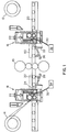
- Fig. 1 illustrates a hot strip mill which includes a rolling mill 10, shown as a four-high rolling mill, for reducing a slab of material to be worked on.
- a pair of coiler furnaces 12 and 14 are provided on opposite sides of the rolling mill 10 with each coiler furnace adapted to coil the material to be worked on after passing through the rolling mill 10.
- a pair of pinch roll and shear combinations 16 and 18 are provided on opposite sides of the rolling mill 10 adjacent the openings of the coiler furnaces 12 and 14.
- a pair of crop removal deflectors 22 and 24 are pivotally coupled to the roller table 20.
- the crop removal deflectors 22 and 24 are positioned immediately adjacent the pinch roll and shear combinations 16 and 18, respectively.
- Pistons 26 and 28 are mounted to the roller table 20 and operate to pivot the crop removal deflectors 22 and 24, respectively.
- Guide plates 30 and 32 extend between a pinch roll and shear combination 16 or 18, and a crop removal bin 34 or 36, respectively, positioned below the respective pinch roll and shear combination.
- the pinch roll and shear combination is best illustrated in Fig. 2.
- the pinch roll and shear combination 16 includes a frame 38 upon which a lower roll 40 is rotatably mounted.
- a stationary lower blade 42 is mounted on the frame 38 adjacent the rotatable lower roll 40.
- a rectilinearly movable carriage 44 is mounted within the frame 38.
- a hydraulic cylinder 46 is attached to the frame 38 and coupled to the carriage 44. The hydraulic cylinder 46 is adapted to move the carriage 44 in a rectilinear manner.
- An upper roll 48 is rotatably mounted on the carriage 44 and is aligned with the lower roll 40 such as to form a pinch roll.
- An upper blade assembly 50 is mounted on the carriage 44 and is aligned with the lower blade 42 to form a shear.
- the upper blade assembly 50 includes a pivotable linkage assembly 52 which attaches an upper blade 54 to the carriage 44.
- a hydraulic cylinder 56 is mounted to the carriage 44 and coupled to the linkage assembly 52. The cylinder 56 operates to pivot the linkage assembly 52 which in turn rectilinearly moves the upper blade 54 relative to the carriage 44.
- the upper blade 54 includes a hold-down bar 58 which is positioned vertically above the lower blade 42 and adjacent the upper blade 54.
- the pinch roll and shear combination 16 and 18 of the present invention provide a compact, economical and efficient pinch roll and shear device for use in rolling mills.
- a slab of material to be worked upon such as the steel slab 60 shown in Fig. 1
- Each pass of the slab 60 through the rolling mill 10 reduces the thickness of the slab 60.
- the slab is reduced to a point until it can be coiled, at which time it will be coiled in one of the two coiler furnaces 12 and 14.
- the coiled material will be passed from one coiler furnace to the other through the rolling mill 10 until the desired, finished product is obtained.
- the pinch rolls of the pinch roll and shear combination will be utilized in the conventional fashion to move the material in and out of the coilers and through the rolling mill.
- the shears of the pinch roll and shear combination can be utilized on the workpiece at any time throughout the process.
- the shears may be utilized to crop the leading and trailing ends of the material being worked upon after the final pass through the rolling mill 10.
- the shears may also be utilized to provide a clean leading edge in the middle of the rolling process.
- the pinch roll of the present invention has been found to work effectively when utilizing an upper roll 48 which has a diameter larger than the diameter of the lower roll 40.
- a 24'' diameter upper roll has been utilized with an 18'' diameter lower roll 40.
- the carriage 44 is provided with a sufficient range of motion to allow the upper roll 48 to be moved completely out of the way (e.g. a 'high pass').
- a 14'' stroke for the hydraulic cylinder 46 provides sufficient range of motion for the carriage 44.
- the present invention may also provide an improved shearing action for cropping the workpiece.
- the compact arrangement of the present invention allows the lower blade 42 to be positioned closely adjacent the lower roll 40. For example, when an 18'' diameter lower roll 40 is utilized, the cutting line 62 formed by the shear is about 20'' from the center line of the lower roll 40. This close proximity may improve the quality of the cut being performed. While a material is being sheared between cooperating blades 42 and 54, it is being held between the pinch rolls 40 and 48 immediately adjacent the cutting line 62. This action will further assist the operation of the hold-down bar 58 in obtaining a smooth shear of the workpiece.
- the present arrangement minimizes the space required for including a shear and pinch roll, as well as minimizing the structural components of these individualized units.
Landscapes
- Engineering & Computer Science (AREA)
- Mechanical Engineering (AREA)
- Metal Rolling (AREA)
Abstract
A pinch roll and shear combination for use in a mill, such as a reversing hot strip mill. The pinch roll and shear combination includes a stationary frame (38) provided with a rotatably mounted lower roll (40) and stationary lower blade (42) adjacent the lower roll (40). A rectilinearly movable carriage (44) is mounted on the frame (38) with a piston (46) for moving the carriage. An upper roll (48) is rotatably mounted on the carriage (44) and cooperates with the lower roll (40) to form a pinch roll. An upper blade assembly (50) is mounted on the carriage and cooperates with the lower blade (42) to form a shear.
Description
- This invention relates to a pinch roll and shear combination for use in rolling mills, specifically for use with coilers on hot strip reversing mills.
- In conventional continuous hot mills, a shear is located between the roughing stand or stands and the finishing train. When a hot reversing mill is employed in lieu of the continuous mill or the finishing train, a shear is likewise positioned well upstream of the hot reversing mill. With the advent of the use of coiler furnaces in conjunction with hot reversing mills, the location of the upstream shear has remained constant, with the upstream coiler furnace being downstream of the shear.
- However, various advantages have been found for providing shears between a coiler and a roll stand, for example, the strip can be additionally trimmed at its leading and trailing ends after the finishing passes by the roll stand. The shear unit has been positioned on the pass line adjacent a pinch roll unit which precedes a coiler, as set forth in U.S. Patent Nos. 4,497,191 and 4,494,395.
- Pinch rolls are used in a number of ways on steel processing lines to control speed of travel or tension of steel strip. One such use is in conjunction with coilers. Examples of such pinch rollers are shown in U.S. Patent Nos. 4,497,191; 3,613,426; 4,430,874 and 4,522,050.
- These prior art devices provide bulky, cumbersome machines for pinch rolling and shearing of material being worked upon. The object of the present invention is to provide a compact, economical and efficient pinch roll and shear combination.
- The present invention provides a pinch roll and shear combination for use in a strip mill, such as in conjunction with a coiler, which forms part of a reversing hot strip mill unit. The pinch roll and shear combination of the present invention includes a frame with a lower roll rotatably mounted on the frame, and a stationary lower blade mounted on the frame adjacent the lower roll. A movable carriage is mounted on the frame for rectilinear motion. A hydraulic cylinder is attached to the frame for moving the carriage. An upper roll is rotatably mounted on the carriage and cooperates with the lower roll on the frame to form a pinch roll. An upper blade assembly is mounted on the carriage, with the upper blade assembly adapted for reciprocating an upper blade relative to the carriage. An upper blade carried on the upper blade assembly cooperates with the lower blade to form a shear.
- Other objects and advantages of the present invention will become apparent in the description of the preferred embodiment in connection with the attached figures, of which:
- Fig. 1 is schematic of a reversing hot strip mill which includes the pinch roll and shear combination of the present invention;
- Fig. 2 is an enlarged view of the pinch roll and shear combination shown in Fig. 1; and
- Fig. 3 is a side view of the upper blade assembly of the pinch roll and shear combination shown in Fig. 2.
- Fig. 1 illustrates a hot strip mill which includes a rolling mill 10, shown as a four-high rolling mill, for reducing a slab of material to be worked on. A pair of
coiler furnaces 12 and 14 are provided on opposite sides of the rolling mill 10 with each coiler furnace adapted to coil the material to be worked on after passing through the rolling mill 10. A pair of pinch roll andshear combinations coiler furnaces 12 and 14. - Within a roller table 20, on either side of the rolling mill 10, a pair of
crop removal deflectors crop removal deflectors shear combinations crop removal deflectors Guide plates shear combination crop removal bin - The pinch roll and shear combination is best illustrated in Fig. 2. The pinch roll and
shear combination 16 includes aframe 38 upon which alower roll 40 is rotatably mounted. A stationarylower blade 42 is mounted on theframe 38 adjacent the rotatablelower roll 40. A rectilinearlymovable carriage 44 is mounted within theframe 38. Ahydraulic cylinder 46 is attached to theframe 38 and coupled to thecarriage 44. Thehydraulic cylinder 46 is adapted to move thecarriage 44 in a rectilinear manner. Anupper roll 48 is rotatably mounted on thecarriage 44 and is aligned with thelower roll 40 such as to form a pinch roll. - An
upper blade assembly 50 is mounted on thecarriage 44 and is aligned with thelower blade 42 to form a shear. As shown in Fig. 3, theupper blade assembly 50 includes apivotable linkage assembly 52 which attaches anupper blade 54 to thecarriage 44. Ahydraulic cylinder 56 is mounted to thecarriage 44 and coupled to thelinkage assembly 52. Thecylinder 56 operates to pivot thelinkage assembly 52 which in turn rectilinearly moves theupper blade 54 relative to thecarriage 44. As shown in Fig. 2, theupper blade 54 includes a hold-down bar 58 which is positioned vertically above thelower blade 42 and adjacent theupper blade 54. - The pinch roll and
shear combination steel slab 60 shown in Fig. 1, is passed back and forth on the roller table 20 through the rolling mill 10. Each pass of theslab 60 through the rolling mill 10 reduces the thickness of theslab 60. The slab is reduced to a point until it can be coiled, at which time it will be coiled in one of the twocoiler furnaces 12 and 14. The coiled material will be passed from one coiler furnace to the other through the rolling mill 10 until the desired, finished product is obtained. During such operation, the pinch rolls of the pinch roll and shear combination will be utilized in the conventional fashion to move the material in and out of the coilers and through the rolling mill. The shears of the pinch roll and shear combination can be utilized on the workpiece at any time throughout the process. For example, the shears may be utilized to crop the leading and trailing ends of the material being worked upon after the final pass through the rolling mill 10. Additionally, the shears may also be utilized to provide a clean leading edge in the middle of the rolling process. - The pinch roll of the present invention has been found to work effectively when utilizing an
upper roll 48 which has a diameter larger than the diameter of thelower roll 40. For example, a 24'' diameter upper roll has been utilized with an 18'' diameterlower roll 40. Additionally, thecarriage 44 is provided with a sufficient range of motion to allow theupper roll 48 to be moved completely out of the way (e.g. a 'high pass'). A 14'' stroke for thehydraulic cylinder 46 provides sufficient range of motion for thecarriage 44. - The present invention may also provide an improved shearing action for cropping the workpiece. The compact arrangement of the present invention allows the
lower blade 42 to be positioned closely adjacent thelower roll 40. For example, when an 18'' diameterlower roll 40 is utilized, thecutting line 62 formed by the shear is about 20'' from the center line of thelower roll 40. This close proximity may improve the quality of the cut being performed. While a material is being sheared between cooperatingblades pinch rolls cutting line 62. This action will further assist the operation of the hold-downbar 58 in obtaining a smooth shear of the workpiece. - The present arrangement minimizes the space required for including a shear and pinch roll, as well as minimizing the structural components of these individualized units.
- It will become apparent to those of ordinary skill in the art that various modifications may be made to this invention without departing from the spirit and scope thereof. Consequently, the scope of the present invention is intended to be limited only by the attached claims.
Claims (10)
- A pinch roll and shear combination comprising:
a frame;
a lower roll rotatably mounted on said frame;
a lower blade mounted on said frame adjacent said lower roll;
a movable carriage mounted on said frame;
a means for moving said carriage;
an upper roll rotatably mounted on said carriage and cooperating with said lower roll to form a pinch roll;
and
an upper blade assembly mounted on said carriage, wherein said upper blade assembly cooperates with said lower blade to form a shear. - The combination of claim 1 wherein said carriage moving means is a hydraulic cylinder mounted on said frame.
- The combination of claim 1 or 2 wherein said upper blade assembly is mounted for movement relative to said carriage.
- The combination of claim 1, 2 or 3 wherein said upper blade assembly includes a pivotable linkage assembly coupling said upper blade assembly to said carriage, a hydraulic cylinder is mounted to said carriage and is coupled to said linkage assembly wherein said hydraulic cylinder operates to pivot said linkage assembly which rectilinearly moves said upper blade assembly relative to said carriage.
- The combination of one of the claims 1 to 4 wherein said upper blade assembly includes a hold-down bar positioned vertically above said lower blade, and an upper blade adjacent said hold-down bar.
- The combination of one of the claims 1 to 5, wherein said upper roll has a diameter which is larger than said lower roll.
- A hot strip mill comprising:
a rolling mill for reducing a slab of material to be worked on;
at least one coiler furnace, with each said coiler furnace adapted to coil the material to be worked on from said rolling mill; and
at least one pinch roll and shear combination according to one of the claims 1 to 6, with each pinch roll and shear combination being provided adjacent one of said at least one coiler furnace. - The hot strip mill of claim 7 wherein a pair of coiler furnaces are provided with said coiler furnaces positioned on opposite sides of said rolling mill; and
a pair of pinch roll and shear combinations provided on opposite sides of said rolling mill. - The hot strip mill of claim 7 or 8, further comprising a pivotable crop removal deflector being positioned adjacent said shear and cooperating with a crop removal bin positioned below said shear and adapted to receive material removed by said shear.
- The hot strip mill of claim 7, 8 or 9, further comprising guide plates extending between said crop removal bin and said lower blade to guide the material removed by said shear to said crop removal bin.
Applications Claiming Priority (2)
| Application Number | Priority Date | Filing Date | Title |
|---|---|---|---|
| US07/961,512 US5285670A (en) | 1992-10-15 | 1992-10-15 | Pinch roll and shear combination |
| US961512 | 1992-10-15 |
Publications (1)
| Publication Number | Publication Date |
|---|---|
| EP0593398A1 true EP0593398A1 (en) | 1994-04-20 |
Family
ID=25504572
Family Applications (1)
| Application Number | Title | Priority Date | Filing Date |
|---|---|---|---|
| EP93810708A Withdrawn EP0593398A1 (en) | 1992-10-15 | 1993-10-06 | Pinch roll and shear combination |
Country Status (5)
| Country | Link |
|---|---|
| US (1) | US5285670A (en) |
| EP (1) | EP0593398A1 (en) |
| KR (1) | KR960008872B1 (en) |
| CN (1) | CN1087847A (en) |
| CA (1) | CA2108400C (en) |
Cited By (3)
| Publication number | Priority date | Publication date | Assignee | Title |
|---|---|---|---|---|
| EP0860248A3 (en) * | 1997-02-25 | 1999-01-13 | Karl Eugen Fischer GmbH Maschinenfabrik | Pressure bar for a shearing cutter |
| WO2004054730A1 (en) * | 2002-12-14 | 2004-07-01 | Sms Demag Aktiengesellschaft | Method and installation for hot-rolling strips using a steckel rolling frame |
| DE102012201418A1 (en) | 2012-02-01 | 2013-08-01 | Sms Siemag Ag | Steckel mill |
Families Citing this family (9)
| Publication number | Priority date | Publication date | Assignee | Title |
|---|---|---|---|---|
| US6264767B1 (en) | 1995-06-07 | 2001-07-24 | Ipsco Enterprises Inc. | Method of producing martensite-or bainite-rich steel using steckel mill and controlled cooling |
| DE69802086T2 (en) * | 1997-07-15 | 2002-06-13 | Danieli & C. Officine Meccaniche S.P.A., Buttrio | WINDING MACHINE FOR HOT-ROLLED ROLLING MATERIALS LIKE BANDS OR SHEETS AND METHOD THEREFOR |
| DE10133756A1 (en) * | 2001-07-11 | 2003-01-30 | Sms Demag Ag | Cold rolling mill and method for cold rolling metallic strip |
| JP2004050220A (en) * | 2002-07-18 | 2004-02-19 | Ishikawajima Harima Heavy Ind Co Ltd | Strip manufacturing equipment |
| UA79184C2 (en) * | 2002-12-14 | 2007-05-25 | Sms Demag Ag | Method and installation for hot-rolling strips using reversible steckel rolling frame |
| DE102004034090A1 (en) * | 2004-07-15 | 2006-02-02 | Sms Demag Ag | Rolling plant for rolling metallic material |
| CN104162714A (en) * | 2014-07-04 | 2014-11-26 | 太原科技大学 | Single hydraulic cylinder driving and roll-cutting type plate shearing machine |
| KR101867679B1 (en) * | 2016-07-28 | 2018-06-15 | 주식회사 포스코 | Strip center position controller |
| CN109834113B (en) * | 2019-03-25 | 2024-04-26 | 中冶南方工程技术有限公司 | Lead processing equipment in coil preparation station |
Citations (9)
| Publication number | Priority date | Publication date | Assignee | Title |
|---|---|---|---|---|
| DE404763C (en) * | 1921-12-25 | 1924-10-24 | Schloemann Akt Ges | Device for cutting rolling rods |
| US3197992A (en) * | 1963-06-11 | 1965-08-03 | Hitachi Ltd | Slitting apparatus for hoop mills |
| US3613426A (en) * | 1968-11-04 | 1971-10-19 | United Eng Foundry Co | Hot reversing strip mill method and apparatus |
| JPS5677006A (en) * | 1979-11-30 | 1981-06-25 | Mitsubishi Heavy Ind Ltd | Strip mill |
| US4337679A (en) * | 1979-07-02 | 1982-07-06 | Krylov Gleb L | Plate shears |
| US4455848A (en) * | 1982-09-13 | 1984-06-26 | Tippins Machinery Company, Inc. | Apparatus for underwinding strip on a drum in a hot reversing mill |
| JPS59156611A (en) * | 1983-02-25 | 1984-09-05 | Kobe Steel Ltd | Shearing machine having course changeover mechanism |
| US4497191A (en) * | 1982-03-05 | 1985-02-05 | Voest-Alpine Aktiengesellschaft | Plant and process for hot-rolling strip or plate stock |
| JPS6076910A (en) * | 1983-09-30 | 1985-05-01 | Mitsubishi Heavy Ind Ltd | Scrap charging device in scrap shear |
Family Cites Families (17)
| Publication number | Priority date | Publication date | Assignee | Title |
|---|---|---|---|---|
| US1918968A (en) * | 1928-01-12 | 1933-07-18 | Robert M Keeney | Rolling mill |
| GB1204817A (en) * | 1967-11-18 | 1970-09-09 | Siemag Siegener Masch Bau | Strip coiler |
| DE2331653B2 (en) * | 1973-06-22 | 1977-05-12 | Meteor-Siegen Apparatebau Paul Schmeck Gmbh, 5900 Siegen | TRANSPORT AND SEPARATION DEVICE FOR RAIL-SHAPED COPY MATERIAL IN PARTICULAR A LIGHTING MACHINE |
| US4043494A (en) * | 1976-02-23 | 1977-08-23 | Amp Incorporated | Apparatus for feeding a plurality of wires |
| US4096724A (en) * | 1977-05-27 | 1978-06-27 | General Motors Corporation | Method of coiling a flat strip |
| US4430874A (en) * | 1981-09-29 | 1984-02-14 | Tippins Machinery Company, Inc. | Vertical coiler furnace and method of rolling |
| JPS5873306A (en) * | 1981-10-23 | 1983-05-02 | ワイケイケイ株式会社 | Slide fastener chain cutting device |
| AT372881B (en) * | 1982-03-05 | 1983-11-25 | Voest Alpine Ag | PLANT FOR THE HOT ROLLING OF TAPE OR TABLED ROLLED GOODS |
| DE3241745C2 (en) * | 1982-11-11 | 1985-08-08 | Mannesmann AG, 4000 Düsseldorf | Process for the production of hot-rolled steel strip from continuously cast raw material in directly successive work steps |
| US4522050A (en) * | 1983-01-14 | 1985-06-11 | Tippins Machinery Company, Inc. | Three stand mini mill method and apparatus |
| US4675974A (en) * | 1985-10-17 | 1987-06-30 | Tippins Machinery Co., Inc. | Method of continuous casting and rolling strip |
| US4793169A (en) * | 1986-06-27 | 1988-12-27 | United Engineering, Inc. | Continuous backpass rolling mill |
| JPS63252604A (en) * | 1987-04-08 | 1988-10-19 | Hitachi Ltd | Continuous casting direct rolling method and equipment |
| JPS63309306A (en) * | 1987-06-11 | 1988-12-16 | Hitachi Ltd | Rolling equipment and rolling method for continuously cast slabs |
| US5079941A (en) * | 1987-07-13 | 1992-01-14 | Hoogovens Groep Bv | Temper mill installation and shearing machine for use in such an installation |
| JP2593534B2 (en) * | 1988-11-11 | 1997-03-26 | 株式会社日立製作所 | Hot rolling equipment |
| US5086634A (en) * | 1990-11-26 | 1992-02-11 | Braner, Inc. | Coil-to-coil steel slitting process |
-
1992
- 1992-10-15 US US07/961,512 patent/US5285670A/en not_active Expired - Lifetime
-
1993
- 1993-10-06 EP EP93810708A patent/EP0593398A1/en not_active Withdrawn
- 1993-10-11 KR KR93020997A patent/KR960008872B1/en not_active Expired - Fee Related
- 1993-10-14 CA CA002108400A patent/CA2108400C/en not_active Expired - Lifetime
- 1993-10-15 CN CN93118933A patent/CN1087847A/en active Pending
Patent Citations (9)
| Publication number | Priority date | Publication date | Assignee | Title |
|---|---|---|---|---|
| DE404763C (en) * | 1921-12-25 | 1924-10-24 | Schloemann Akt Ges | Device for cutting rolling rods |
| US3197992A (en) * | 1963-06-11 | 1965-08-03 | Hitachi Ltd | Slitting apparatus for hoop mills |
| US3613426A (en) * | 1968-11-04 | 1971-10-19 | United Eng Foundry Co | Hot reversing strip mill method and apparatus |
| US4337679A (en) * | 1979-07-02 | 1982-07-06 | Krylov Gleb L | Plate shears |
| JPS5677006A (en) * | 1979-11-30 | 1981-06-25 | Mitsubishi Heavy Ind Ltd | Strip mill |
| US4497191A (en) * | 1982-03-05 | 1985-02-05 | Voest-Alpine Aktiengesellschaft | Plant and process for hot-rolling strip or plate stock |
| US4455848A (en) * | 1982-09-13 | 1984-06-26 | Tippins Machinery Company, Inc. | Apparatus for underwinding strip on a drum in a hot reversing mill |
| JPS59156611A (en) * | 1983-02-25 | 1984-09-05 | Kobe Steel Ltd | Shearing machine having course changeover mechanism |
| JPS6076910A (en) * | 1983-09-30 | 1985-05-01 | Mitsubishi Heavy Ind Ltd | Scrap charging device in scrap shear |
Non-Patent Citations (3)
| Title |
|---|
| PATENT ABSTRACTS OF JAPAN vol. 5, no. 147 (M - 88) 17 September 1981 (1981-09-17) * |
| PATENT ABSTRACTS OF JAPAN vol. 9, no. 219 (M - 410) 6 September 1985 (1985-09-06) * |
| PATENT ABSTRACTS OF JAPAN vol. 9, no. 7 (M - 350) 12 January 1985 (1985-01-12) * |
Cited By (6)
| Publication number | Priority date | Publication date | Assignee | Title |
|---|---|---|---|---|
| EP0860248A3 (en) * | 1997-02-25 | 1999-01-13 | Karl Eugen Fischer GmbH Maschinenfabrik | Pressure bar for a shearing cutter |
| WO2004054730A1 (en) * | 2002-12-14 | 2004-07-01 | Sms Demag Aktiengesellschaft | Method and installation for hot-rolling strips using a steckel rolling frame |
| US7121130B2 (en) | 2002-12-14 | 2006-10-17 | Sms Demag Ag | Method and installation for hot-rolling strips using a Steckel rolling frame |
| DE102012201418A1 (en) | 2012-02-01 | 2013-08-01 | Sms Siemag Ag | Steckel mill |
| WO2013113809A1 (en) | 2012-02-01 | 2013-08-08 | Sms Siemag Ag | Steckel mill |
| RU2578335C1 (en) * | 2012-02-01 | 2016-03-27 | Смс Зимаг Аг | Steckel rolling mill |
Also Published As
| Publication number | Publication date |
|---|---|
| CN1087847A (en) | 1994-06-15 |
| CA2108400C (en) | 1997-01-14 |
| KR960008872B1 (en) | 1996-07-05 |
| KR940008765A (en) | 1994-05-16 |
| CA2108400A1 (en) | 1994-04-16 |
| US5285670A (en) | 1994-02-15 |
Similar Documents
| Publication | Publication Date | Title |
|---|---|---|
| US5285670A (en) | Pinch roll and shear combination | |
| EP0371281B1 (en) | Apparatus for producing hot-rolled steel strip | |
| EP1330324B1 (en) | Compact rotary shears | |
| EP0224333B2 (en) | Press apparatus for reducing widths of hot slabs | |
| DE69712429T2 (en) | Method of welding billets taken out of an oven and rolling machine using this method | |
| US4995541A (en) | Set of guide rolls for guiding, positioning and controlling motion of bands of material fed through the rolls | |
| CN109531176B (en) | Online trimming device and online trimming method in strip steel casting and rolling production process | |
| EP1575718B1 (en) | Method and installation for hot-rolling strips using a steckel rolling frame | |
| EP0470436B1 (en) | Pressure roll for holding slabs down in an upsetting press | |
| US4319474A (en) | Rolling method and apparatus | |
| EP0088201B1 (en) | Arrangement for the hot-rolling of metal strip or platelike rolling stock | |
| DE3803592A1 (en) | METHOD AND PLANT FOR ROLLING TUBES PRESENTED ON A BELT CASTING PLANT | |
| DE2900648A1 (en) | METHOD AND DEVICE FOR ROLLING GROUND SHEETS | |
| CN1538884A (en) | Hot rolling equipment | |
| CN100357043C (en) | Method and installation for hot-rolling strips using a steckel rolling frame | |
| DE3311116A1 (en) | Method and device for aligning plates on a roller table | |
| EP0501211B1 (en) | Method of operating an upsetting press | |
| AT219381B (en) | Sheet metal shears for shear lines in sheet metal rolling mills, in particular heavy plate mills and shear lines adapted to them | |
| US5860345A (en) | Transversely movable thread sled | |
| EP0045400B1 (en) | Installation for direct-strand reduction of steel at high velocities | |
| EP0162020B1 (en) | Method and apparatus for allowing the free passage of heavy-gauge material through a flying drum shear | |
| CN209288728U (en) | Online edge cutting device in strip steel casting and rolling production process | |
| KR100302959B1 (en) | Apparatus for automatically shearing rolled plate | |
| EP0431058B1 (en) | Treatment of metal slabs | |
| CN221133580U (en) | Steel strip rolling mill |
Legal Events
| Date | Code | Title | Description |
|---|---|---|---|
| PUAI | Public reference made under article 153(3) epc to a published international application that has entered the european phase |
Free format text: ORIGINAL CODE: 0009012 |
|
| AK | Designated contracting states |
Kind code of ref document: A1 Designated state(s): AT BE DE DK FR GB IT NL SE |
|
| STAA | Information on the status of an ep patent application or granted ep patent |
Free format text: STATUS: THE APPLICATION IS DEEMED TO BE WITHDRAWN |
|
| 18D | Application deemed to be withdrawn |
Effective date: 19941021 |