EP0593782A1 - Hydraulic circuit device for construction machines - Google Patents
Hydraulic circuit device for construction machines Download PDFInfo
- Publication number
- EP0593782A1 EP0593782A1 EP93908117A EP93908117A EP0593782A1 EP 0593782 A1 EP0593782 A1 EP 0593782A1 EP 93908117 A EP93908117 A EP 93908117A EP 93908117 A EP93908117 A EP 93908117A EP 0593782 A1 EP0593782 A1 EP 0593782A1
- Authority
- EP
- European Patent Office
- Prior art keywords
- pressure
- directional control
- traveling
- hydraulic
- control valve
- Prior art date
- Legal status (The legal status is an assumption and is not a legal conclusion. Google has not performed a legal analysis and makes no representation as to the accuracy of the status listed.)
- Granted
Links
- 238000010276 construction Methods 0.000 title claims abstract description 17
- 239000012530 fluid Substances 0.000 claims description 106
- 230000001419 dependent effect Effects 0.000 claims description 2
- 238000010586 diagram Methods 0.000 description 10
- 238000011144 upstream manufacturing Methods 0.000 description 10
- 230000007935 neutral effect Effects 0.000 description 7
- 230000009194 climbing Effects 0.000 description 3
- 230000007423 decrease Effects 0.000 description 3
- 230000035939 shock Effects 0.000 description 3
- 238000006073 displacement reaction Methods 0.000 description 2
- 230000000694 effects Effects 0.000 description 2
- 230000003247 decreasing effect Effects 0.000 description 1
- 230000006866 deterioration Effects 0.000 description 1
- 230000002542 deteriorative effect Effects 0.000 description 1
Images






Classifications
-
- F—MECHANICAL ENGINEERING; LIGHTING; HEATING; WEAPONS; BLASTING
- F15—FLUID-PRESSURE ACTUATORS; HYDRAULICS OR PNEUMATICS IN GENERAL
- F15B—SYSTEMS ACTING BY MEANS OF FLUIDS IN GENERAL; FLUID-PRESSURE ACTUATORS, e.g. SERVOMOTORS; DETAILS OF FLUID-PRESSURE SYSTEMS, NOT OTHERWISE PROVIDED FOR
- F15B13/00—Details of servomotor systems ; Valves for servomotor systems
- F15B13/02—Fluid distribution or supply devices characterised by their adaptation to the control of servomotors
- F15B13/04—Fluid distribution or supply devices characterised by their adaptation to the control of servomotors for use with a single servomotor
- F15B13/0401—Valve members; Fluid interconnections therefor
- F15B13/0402—Valve members; Fluid interconnections therefor for linearly sliding valves, e.g. spool valves
- F15B13/0403—Valve members; Fluid interconnections therefor for linearly sliding valves, e.g. spool valves a secondary valve member sliding within the main spool, e.g. for regeneration flow
-
- E—FIXED CONSTRUCTIONS
- E02—HYDRAULIC ENGINEERING; FOUNDATIONS; SOIL SHIFTING
- E02F—DREDGING; SOIL-SHIFTING
- E02F9/00—Component parts of dredgers or soil-shifting machines, not restricted to one of the kinds covered by groups E02F3/00 - E02F7/00
- E02F9/20—Drives; Control devices
- E02F9/22—Hydraulic or pneumatic drives
- E02F9/2221—Control of flow rate; Load sensing arrangements
- E02F9/2232—Control of flow rate; Load sensing arrangements using one or more variable displacement pumps
-
- E—FIXED CONSTRUCTIONS
- E02—HYDRAULIC ENGINEERING; FOUNDATIONS; SOIL SHIFTING
- E02F—DREDGING; SOIL-SHIFTING
- E02F9/00—Component parts of dredgers or soil-shifting machines, not restricted to one of the kinds covered by groups E02F3/00 - E02F7/00
- E02F9/20—Drives; Control devices
- E02F9/22—Hydraulic or pneumatic drives
- E02F9/2221—Control of flow rate; Load sensing arrangements
- E02F9/2239—Control of flow rate; Load sensing arrangements using two or more pumps with cross-assistance
-
- E—FIXED CONSTRUCTIONS
- E02—HYDRAULIC ENGINEERING; FOUNDATIONS; SOIL SHIFTING
- E02F—DREDGING; SOIL-SHIFTING
- E02F9/00—Component parts of dredgers or soil-shifting machines, not restricted to one of the kinds covered by groups E02F3/00 - E02F7/00
- E02F9/20—Drives; Control devices
- E02F9/22—Hydraulic or pneumatic drives
- E02F9/2278—Hydraulic circuits
- E02F9/2282—Systems using center bypass type changeover valves
-
- E—FIXED CONSTRUCTIONS
- E02—HYDRAULIC ENGINEERING; FOUNDATIONS; SOIL SHIFTING
- E02F—DREDGING; SOIL-SHIFTING
- E02F9/00—Component parts of dredgers or soil-shifting machines, not restricted to one of the kinds covered by groups E02F3/00 - E02F7/00
- E02F9/20—Drives; Control devices
- E02F9/22—Hydraulic or pneumatic drives
- E02F9/2278—Hydraulic circuits
- E02F9/2285—Pilot-operated systems
-
- E—FIXED CONSTRUCTIONS
- E02—HYDRAULIC ENGINEERING; FOUNDATIONS; SOIL SHIFTING
- E02F—DREDGING; SOIL-SHIFTING
- E02F9/00—Component parts of dredgers or soil-shifting machines, not restricted to one of the kinds covered by groups E02F3/00 - E02F7/00
- E02F9/20—Drives; Control devices
- E02F9/22—Hydraulic or pneumatic drives
- E02F9/2278—Hydraulic circuits
- E02F9/2292—Systems with two or more pumps
-
- E—FIXED CONSTRUCTIONS
- E02—HYDRAULIC ENGINEERING; FOUNDATIONS; SOIL SHIFTING
- E02F—DREDGING; SOIL-SHIFTING
- E02F9/00—Component parts of dredgers or soil-shifting machines, not restricted to one of the kinds covered by groups E02F3/00 - E02F7/00
- E02F9/20—Drives; Control devices
- E02F9/22—Hydraulic or pneumatic drives
- E02F9/2278—Hydraulic circuits
- E02F9/2296—Systems with a variable displacement pump
-
- F—MECHANICAL ENGINEERING; LIGHTING; HEATING; WEAPONS; BLASTING
- F15—FLUID-PRESSURE ACTUATORS; HYDRAULICS OR PNEUMATICS IN GENERAL
- F15B—SYSTEMS ACTING BY MEANS OF FLUIDS IN GENERAL; FLUID-PRESSURE ACTUATORS, e.g. SERVOMOTORS; DETAILS OF FLUID-PRESSURE SYSTEMS, NOT OTHERWISE PROVIDED FOR
- F15B11/00—Servomotor systems without provision for follow-up action; Circuits therefor
- F15B11/16—Servomotor systems without provision for follow-up action; Circuits therefor with two or more servomotors
- F15B11/161—Servomotor systems without provision for follow-up action; Circuits therefor with two or more servomotors with sensing of servomotor demand or load
-
- F—MECHANICAL ENGINEERING; LIGHTING; HEATING; WEAPONS; BLASTING
- F15—FLUID-PRESSURE ACTUATORS; HYDRAULICS OR PNEUMATICS IN GENERAL
- F15B—SYSTEMS ACTING BY MEANS OF FLUIDS IN GENERAL; FLUID-PRESSURE ACTUATORS, e.g. SERVOMOTORS; DETAILS OF FLUID-PRESSURE SYSTEMS, NOT OTHERWISE PROVIDED FOR
- F15B11/00—Servomotor systems without provision for follow-up action; Circuits therefor
- F15B11/16—Servomotor systems without provision for follow-up action; Circuits therefor with two or more servomotors
- F15B11/17—Servomotor systems without provision for follow-up action; Circuits therefor with two or more servomotors using two or more pumps
-
- F—MECHANICAL ENGINEERING; LIGHTING; HEATING; WEAPONS; BLASTING
- F15—FLUID-PRESSURE ACTUATORS; HYDRAULICS OR PNEUMATICS IN GENERAL
- F15B—SYSTEMS ACTING BY MEANS OF FLUIDS IN GENERAL; FLUID-PRESSURE ACTUATORS, e.g. SERVOMOTORS; DETAILS OF FLUID-PRESSURE SYSTEMS, NOT OTHERWISE PROVIDED FOR
- F15B13/00—Details of servomotor systems ; Valves for servomotor systems
- F15B13/02—Fluid distribution or supply devices characterised by their adaptation to the control of servomotors
- F15B13/04—Fluid distribution or supply devices characterised by their adaptation to the control of servomotors for use with a single servomotor
- F15B13/0416—Fluid distribution or supply devices characterised by their adaptation to the control of servomotors for use with a single servomotor with means or adapted for load sensing
- F15B13/0417—Load sensing elements; Internal fluid connections therefor; Anti-saturation or pressure-compensation valves
- F15B13/0418—Load sensing elements sliding within a hollow main valve spool
-
- F—MECHANICAL ENGINEERING; LIGHTING; HEATING; WEAPONS; BLASTING
- F15—FLUID-PRESSURE ACTUATORS; HYDRAULICS OR PNEUMATICS IN GENERAL
- F15B—SYSTEMS ACTING BY MEANS OF FLUIDS IN GENERAL; FLUID-PRESSURE ACTUATORS, e.g. SERVOMOTORS; DETAILS OF FLUID-PRESSURE SYSTEMS, NOT OTHERWISE PROVIDED FOR
- F15B2211/00—Circuits for servomotor systems
- F15B2211/20—Fluid pressure source, e.g. accumulator or variable axial piston pump
- F15B2211/205—Systems with pumps
- F15B2211/2053—Type of pump
- F15B2211/20546—Type of pump variable capacity
- F15B2211/20553—Type of pump variable capacity with pilot circuit, e.g. for controlling a swash plate
-
- F—MECHANICAL ENGINEERING; LIGHTING; HEATING; WEAPONS; BLASTING
- F15—FLUID-PRESSURE ACTUATORS; HYDRAULICS OR PNEUMATICS IN GENERAL
- F15B—SYSTEMS ACTING BY MEANS OF FLUIDS IN GENERAL; FLUID-PRESSURE ACTUATORS, e.g. SERVOMOTORS; DETAILS OF FLUID-PRESSURE SYSTEMS, NOT OTHERWISE PROVIDED FOR
- F15B2211/00—Circuits for servomotor systems
- F15B2211/20—Fluid pressure source, e.g. accumulator or variable axial piston pump
- F15B2211/205—Systems with pumps
- F15B2211/20576—Systems with pumps with multiple pumps
-
- F—MECHANICAL ENGINEERING; LIGHTING; HEATING; WEAPONS; BLASTING
- F15—FLUID-PRESSURE ACTUATORS; HYDRAULICS OR PNEUMATICS IN GENERAL
- F15B—SYSTEMS ACTING BY MEANS OF FLUIDS IN GENERAL; FLUID-PRESSURE ACTUATORS, e.g. SERVOMOTORS; DETAILS OF FLUID-PRESSURE SYSTEMS, NOT OTHERWISE PROVIDED FOR
- F15B2211/00—Circuits for servomotor systems
- F15B2211/30—Directional control
- F15B2211/305—Directional control characterised by the type of valves
- F15B2211/30525—Directional control valves, e.g. 4/3-directional control valve
- F15B2211/3053—In combination with a pressure compensating valve
- F15B2211/30555—Inlet and outlet of the pressure compensating valve being connected to the directional control valve
-
- F—MECHANICAL ENGINEERING; LIGHTING; HEATING; WEAPONS; BLASTING
- F15—FLUID-PRESSURE ACTUATORS; HYDRAULICS OR PNEUMATICS IN GENERAL
- F15B—SYSTEMS ACTING BY MEANS OF FLUIDS IN GENERAL; FLUID-PRESSURE ACTUATORS, e.g. SERVOMOTORS; DETAILS OF FLUID-PRESSURE SYSTEMS, NOT OTHERWISE PROVIDED FOR
- F15B2211/00—Circuits for servomotor systems
- F15B2211/30—Directional control
- F15B2211/31—Directional control characterised by the positions of the valve element
- F15B2211/3105—Neutral or centre positions
- F15B2211/3116—Neutral or centre positions the pump port being open in the centre position, e.g. so-called open centre
-
- F—MECHANICAL ENGINEERING; LIGHTING; HEATING; WEAPONS; BLASTING
- F15—FLUID-PRESSURE ACTUATORS; HYDRAULICS OR PNEUMATICS IN GENERAL
- F15B—SYSTEMS ACTING BY MEANS OF FLUIDS IN GENERAL; FLUID-PRESSURE ACTUATORS, e.g. SERVOMOTORS; DETAILS OF FLUID-PRESSURE SYSTEMS, NOT OTHERWISE PROVIDED FOR
- F15B2211/00—Circuits for servomotor systems
- F15B2211/30—Directional control
- F15B2211/31—Directional control characterised by the positions of the valve element
- F15B2211/3122—Special positions other than the pump port being connected to working ports or the working ports being connected to the return line
- F15B2211/3127—Floating position connecting the working ports and the return line
-
- F—MECHANICAL ENGINEERING; LIGHTING; HEATING; WEAPONS; BLASTING
- F15—FLUID-PRESSURE ACTUATORS; HYDRAULICS OR PNEUMATICS IN GENERAL
- F15B—SYSTEMS ACTING BY MEANS OF FLUIDS IN GENERAL; FLUID-PRESSURE ACTUATORS, e.g. SERVOMOTORS; DETAILS OF FLUID-PRESSURE SYSTEMS, NOT OTHERWISE PROVIDED FOR
- F15B2211/00—Circuits for servomotor systems
- F15B2211/30—Directional control
- F15B2211/32—Directional control characterised by the type of actuation
- F15B2211/329—Directional control characterised by the type of actuation actuated by fluid pressure
-
- F—MECHANICAL ENGINEERING; LIGHTING; HEATING; WEAPONS; BLASTING
- F15—FLUID-PRESSURE ACTUATORS; HYDRAULICS OR PNEUMATICS IN GENERAL
- F15B—SYSTEMS ACTING BY MEANS OF FLUIDS IN GENERAL; FLUID-PRESSURE ACTUATORS, e.g. SERVOMOTORS; DETAILS OF FLUID-PRESSURE SYSTEMS, NOT OTHERWISE PROVIDED FOR
- F15B2211/00—Circuits for servomotor systems
- F15B2211/30—Directional control
- F15B2211/35—Directional control combined with flow control
- F15B2211/351—Flow control by regulating means in feed line, i.e. meter-in control
-
- F—MECHANICAL ENGINEERING; LIGHTING; HEATING; WEAPONS; BLASTING
- F15—FLUID-PRESSURE ACTUATORS; HYDRAULICS OR PNEUMATICS IN GENERAL
- F15B—SYSTEMS ACTING BY MEANS OF FLUIDS IN GENERAL; FLUID-PRESSURE ACTUATORS, e.g. SERVOMOTORS; DETAILS OF FLUID-PRESSURE SYSTEMS, NOT OTHERWISE PROVIDED FOR
- F15B2211/00—Circuits for servomotor systems
- F15B2211/30—Directional control
- F15B2211/365—Directional control combined with flow control and pressure control
-
- F—MECHANICAL ENGINEERING; LIGHTING; HEATING; WEAPONS; BLASTING
- F15—FLUID-PRESSURE ACTUATORS; HYDRAULICS OR PNEUMATICS IN GENERAL
- F15B—SYSTEMS ACTING BY MEANS OF FLUIDS IN GENERAL; FLUID-PRESSURE ACTUATORS, e.g. SERVOMOTORS; DETAILS OF FLUID-PRESSURE SYSTEMS, NOT OTHERWISE PROVIDED FOR
- F15B2211/00—Circuits for servomotor systems
- F15B2211/40—Flow control
- F15B2211/405—Flow control characterised by the type of flow control means or valve
- F15B2211/40515—Flow control characterised by the type of flow control means or valve with variable throttles or orifices
-
- F—MECHANICAL ENGINEERING; LIGHTING; HEATING; WEAPONS; BLASTING
- F15—FLUID-PRESSURE ACTUATORS; HYDRAULICS OR PNEUMATICS IN GENERAL
- F15B—SYSTEMS ACTING BY MEANS OF FLUIDS IN GENERAL; FLUID-PRESSURE ACTUATORS, e.g. SERVOMOTORS; DETAILS OF FLUID-PRESSURE SYSTEMS, NOT OTHERWISE PROVIDED FOR
- F15B2211/00—Circuits for servomotor systems
- F15B2211/40—Flow control
- F15B2211/42—Flow control characterised by the type of actuation
- F15B2211/428—Flow control characterised by the type of actuation actuated by fluid pressure
-
- F—MECHANICAL ENGINEERING; LIGHTING; HEATING; WEAPONS; BLASTING
- F15—FLUID-PRESSURE ACTUATORS; HYDRAULICS OR PNEUMATICS IN GENERAL
- F15B—SYSTEMS ACTING BY MEANS OF FLUIDS IN GENERAL; FLUID-PRESSURE ACTUATORS, e.g. SERVOMOTORS; DETAILS OF FLUID-PRESSURE SYSTEMS, NOT OTHERWISE PROVIDED FOR
- F15B2211/00—Circuits for servomotor systems
- F15B2211/40—Flow control
- F15B2211/45—Control of bleed-off flow, e.g. control of bypass flow to the return line
-
- F—MECHANICAL ENGINEERING; LIGHTING; HEATING; WEAPONS; BLASTING
- F15—FLUID-PRESSURE ACTUATORS; HYDRAULICS OR PNEUMATICS IN GENERAL
- F15B—SYSTEMS ACTING BY MEANS OF FLUIDS IN GENERAL; FLUID-PRESSURE ACTUATORS, e.g. SERVOMOTORS; DETAILS OF FLUID-PRESSURE SYSTEMS, NOT OTHERWISE PROVIDED FOR
- F15B2211/00—Circuits for servomotor systems
- F15B2211/60—Circuit components or control therefor
- F15B2211/605—Load sensing circuits
- F15B2211/6051—Load sensing circuits having valve means between output member and the load sensing circuit
- F15B2211/6054—Load sensing circuits having valve means between output member and the load sensing circuit using shuttle valves
-
- F—MECHANICAL ENGINEERING; LIGHTING; HEATING; WEAPONS; BLASTING
- F15—FLUID-PRESSURE ACTUATORS; HYDRAULICS OR PNEUMATICS IN GENERAL
- F15B—SYSTEMS ACTING BY MEANS OF FLUIDS IN GENERAL; FLUID-PRESSURE ACTUATORS, e.g. SERVOMOTORS; DETAILS OF FLUID-PRESSURE SYSTEMS, NOT OTHERWISE PROVIDED FOR
- F15B2211/00—Circuits for servomotor systems
- F15B2211/60—Circuit components or control therefor
- F15B2211/605—Load sensing circuits
- F15B2211/6051—Load sensing circuits having valve means between output member and the load sensing circuit
- F15B2211/6057—Load sensing circuits having valve means between output member and the load sensing circuit using directional control valves
-
- F—MECHANICAL ENGINEERING; LIGHTING; HEATING; WEAPONS; BLASTING
- F15—FLUID-PRESSURE ACTUATORS; HYDRAULICS OR PNEUMATICS IN GENERAL
- F15B—SYSTEMS ACTING BY MEANS OF FLUIDS IN GENERAL; FLUID-PRESSURE ACTUATORS, e.g. SERVOMOTORS; DETAILS OF FLUID-PRESSURE SYSTEMS, NOT OTHERWISE PROVIDED FOR
- F15B2211/00—Circuits for servomotor systems
- F15B2211/60—Circuit components or control therefor
- F15B2211/635—Circuits providing pilot pressure to pilot pressure-controlled fluid circuit elements
- F15B2211/6355—Circuits providing pilot pressure to pilot pressure-controlled fluid circuit elements having valve means
-
- F—MECHANICAL ENGINEERING; LIGHTING; HEATING; WEAPONS; BLASTING
- F15—FLUID-PRESSURE ACTUATORS; HYDRAULICS OR PNEUMATICS IN GENERAL
- F15B—SYSTEMS ACTING BY MEANS OF FLUIDS IN GENERAL; FLUID-PRESSURE ACTUATORS, e.g. SERVOMOTORS; DETAILS OF FLUID-PRESSURE SYSTEMS, NOT OTHERWISE PROVIDED FOR
- F15B2211/00—Circuits for servomotor systems
- F15B2211/70—Output members, e.g. hydraulic motors or cylinders or control therefor
- F15B2211/705—Output members, e.g. hydraulic motors or cylinders or control therefor characterised by the type of output members or actuators
- F15B2211/7058—Rotary output members
-
- F—MECHANICAL ENGINEERING; LIGHTING; HEATING; WEAPONS; BLASTING
- F15—FLUID-PRESSURE ACTUATORS; HYDRAULICS OR PNEUMATICS IN GENERAL
- F15B—SYSTEMS ACTING BY MEANS OF FLUIDS IN GENERAL; FLUID-PRESSURE ACTUATORS, e.g. SERVOMOTORS; DETAILS OF FLUID-PRESSURE SYSTEMS, NOT OTHERWISE PROVIDED FOR
- F15B2211/00—Circuits for servomotor systems
- F15B2211/70—Output members, e.g. hydraulic motors or cylinders or control therefor
- F15B2211/71—Multiple output members, e.g. multiple hydraulic motors or cylinders
- F15B2211/7142—Multiple output members, e.g. multiple hydraulic motors or cylinders the output members being arranged in multiple groups
-
- F—MECHANICAL ENGINEERING; LIGHTING; HEATING; WEAPONS; BLASTING
- F15—FLUID-PRESSURE ACTUATORS; HYDRAULICS OR PNEUMATICS IN GENERAL
- F15B—SYSTEMS ACTING BY MEANS OF FLUIDS IN GENERAL; FLUID-PRESSURE ACTUATORS, e.g. SERVOMOTORS; DETAILS OF FLUID-PRESSURE SYSTEMS, NOT OTHERWISE PROVIDED FOR
- F15B2211/00—Circuits for servomotor systems
- F15B2211/70—Output members, e.g. hydraulic motors or cylinders or control therefor
- F15B2211/78—Control of multiple output members
Definitions
- This invention relates to a hydraulic circuit system for civil engineering and construction machines such as a hydraulic excavator, and more particularly to a hydraulic circuit system for civil engineering and construction machines of the type having right and left crawler belts driven by means of right and left traveling motors, which enables a combined operation of traveling and performing other works.
- Prior art hydraulic circuit systems comprise, as disclosed in JP, B, 2-16416, first and second hydraulic pumps, a plurality of hydraulic actuators driven by hydraulic fluid delivered from the first and second hydraulic pumps, a first group of valves connected to a delivery line of the first hydraulic pump for controlling flow rates of hydraulic fluid supplied to the associated hydraulic actuators and a second group of valves connected to an delivery line of the second hydraulic pump for controlling flow rates of hydraulic fluid supplied to the associated hydraulic actuators.
- the plurality of hydraulic actuators contains first and second traveling motors for driving right and left crawler belts of, for example, a hydraulic excavator and a plurality of working actuators except the first and second traveling motors including a swing motor of, for example, the hydraulic excavator for driving a swing, an arm cylinder for driving an arm, a boom cylinder for driving a boom and a bucket cylinder for driving a bucket.
- first and second traveling motors including a swing motor of, for example, the hydraulic excavator for driving a swing, an arm cylinder for driving an arm, a boom cylinder for driving a boom and a bucket cylinder for driving a bucket.
- the first group of valves includes a first traveling directional control valve for controlling a flow rate of hydraulic fluid supplied to the first traveling motor, and a plurality of first directional control valves for controlling flow rates of hydraulic fluid supplied to part of the plurality of working actuators including, for example, a swing directional control valve, a first arm directional control valve, and a first boom directional control valve, these first directional control valves being connected in tandem to the first traveling directional control valve so as to supply hydraulic fluid from the first hydraulic pump to the associated working actuators with priority over the first traveling motor.
- the second group of valves includes a plurality of second directional control valves for controlling flow rates of hydraulic fluid supplied to part of the plurality of working actuators including, for example, a second boom directional control valve, a bucket directional control valve and a second arm directional control valve, and a second traveling directional control valve for controlling a flow rate of hydraulic fluid supplied to the second traveling motor, the second traveling directional control valve being connected in tandem to the second directional control valves so as to supply hydraulic fluid from the second hydraulic pump to the second traveling motor with priority over the associated working actuators.
- the hydraulic circuit system further contains a circuit for communication of a hydraulic fluid supply circuit of the second traveling directional control valve with a hydraulic fluid supply circuit of the first traveling directional control valve when at least one of a plurality of working actuators except the first and second traveling motors is operated.
- This communication circuit includes a branch line connecting the delivery line of the second hydraulic pump with an inlet port of the first traveling directional control valve, an on-off valve provided in the branch line for opening and closing thereof, and a check valve provided in the downstream of the on-off valve for preventing a reverse flow of hydraulic fluid.
- the on-off valve is maintained at its closed position when the first and second directional control valves associate with the working actuators are not activated, and switched to its open position when the first and second directional control valves are activated.
- This prior art is intended mainly to improve performance of a combined operation of traveling while operating the swing, boom and arm, simultaneously.
- any one of the first directional control valves included in the first group of valves is operated in such a traveling condition, hydraulic fluid from the first hydraulic pump is preferentially supplied to the first directional control valve and since the on-off valve is switched to its open position, hydraulic fluid from the second hydraulic pump is supplied to the first and second traveling directional control valves. That is, the first and second traveling motors are supplied with hydraulic fluid from only the second hydraulic pump, thereby making it possible to implement the combined operation of traveling and performing other works.
- the above described prior art has attained an excellent combined operability of traveling straight on a plane and performing other works.
- the first and second traveling directional control valves are connected in parallel, where a load pressure of the first traveling motor is lower than a load pressure of the second traveling motor, all the amount of hydraulic fluid from the second hydraulic pump flows into the first traveling motor and the operation of the second traveling motor may become unfunctional.
- the front actuators e.g.
- the object of the present invention is achieved by providing a hydraulic circuit system for civil engineering and construction machines comprising first and second hydraulic pumps a plurality of hydraulic actuators driven by hydraulic fluid delivered from the first and second hydraulic pumps; a first group of valves connected to a delivery line of the first hydraulic pump for controlling flow rates of hydraulic fluid supplied to the associated hydraulic actuators; and a second group of valves connected to a delivery line of the second hydraulic pump for controlling flow rates of hydraulic fluid supplied to the associated hydraulic actuators; the plurality of hydraulic actuators including first and second traveling motors for driving a pair of traveling devices, respectively, and a plurality of working actuators for driving a plurality of working elements, respectively, the first group of valves including a first traveling directional control valve for controlling a flow rate of hydraulic fluid supplied to the first traveling motor and a plurality of first directional control valves for controlling flow rates of hydraulic fluid supplied to at least part of the plurality of working actuators, the plurality of first directional control valves being connected to the first traveling directional control valve so as to supply a hydraulic fluid from
- This pressure is supplied to the first pressure adjusting means for controlling the pressure downstream of the first variable restrictor and the second pressure adjusting means for controlling the pressure downstream of the second variable restrictor. Consequently, the pressures downstream of the first and second variable restrictors are controlled to mutually equalize the maximum load pressures.
- the pressures upstream of these first and second variable restrictors are the pressures of hydraulic fluid from the second hydraulic pump and equal to each other.
- the differential between the pressures upstream and downstream of the first variable restrictor and the differential between the pressures upstream and downstream of the second variable restrictor become equal to each other, so that regardless of the difference of load pressures between the first traveling motor and the second traveling motor, the first traveling motor and the second traveling motor are each supplied with a flow rate of hydraulic fluid corresponding to the opening areas of the first and second variable restrictors. This ensures that even if the load pressure of the first traveling motor happens to become low, the second traveling motor is supplied with hydraulic fluid whereby the second traveling motor is prevented from stopping to avoid the possibility of a traveling failure.
- the signal selection means is adapted to supply said maximum load pressure to the first and second pressure adjusting means as the first and second signal pressures when at least one of the plurality of working actuators is activated.
- the signal selection means preferably includes an operation detecting means for detecting at least one of operations of the plurality of working actuators and at least one signal selection valves for supplying the load pressures of the associated actuators to the first and second pressure adjusting means as the first and second signal pressures when no operation is detected by a signal from the operation detecting means and supplying the maximum load pressure to the first and second pressure adjusting means when the operation is detected.
- the first and second pressure adjusting means includes pressure adjusting valves incorporated in the first and second traveling directional control valves, respectively.
- the signal selection means includes first and second signal selection valves provided for the first and second pressure adjusting means, respectively.
- the signal selection means may include a single signal selection valve provided in common to the first and second pressure adjusting means.
- the first and second pressure adjusting means are incorporated in the first and second traveling directional control valves, respectively, and the signal selection means includes selection passages which open or close dependent upon stroke positions of respective spools of the first and second traveling directional control valves.
- the signal selection means preferably supplies the maximum load pressure to the first and second pressure adjusting means as the first and second signal pressures when at least one of the plurality of working actuators is activated.
- Fig. 1 is a diagram illustrating the configuration of a hydraulic circuit system for civil engineering and construction machines according to the first embodiment of the present invention.
- Fig. 2 is a diagram illustrating the details of the first and second groups of valves shown in Fig. 1.
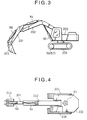
- Fig. 3 is a side view of a hydraulic excavator on which the hydraulic circuit system shown in Fig. 1 is to be mounted.
- Fig. 5 is a diagram illustrating the configuration of a control lever device for operating a directional control valve of the group of valves shown in Fig. 1 and an operation detecting system for detecting the operation of those directional control valves.
- Fig. 6 is a circuit diagram illustrating the configuration of a hydraulic circuit system according to the third embodiment of the present invention.
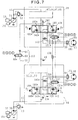
- Fig. 7 is a circuit diagram showing the hydraulic circuit system according to the third embodiment of the present invention.
- Fig. 8 is a cross-sectional view illustrating major portions of the directional control valve shown in Fig. 7.
- Fig. 9 is a circuit diagram illustrating the configuration of a hydraulic circuit system according to the fourth embodiment of the present invention.
- Fig. 10 is a circuit diagram illustrating the configuration of a hydraulic circuit system according to the fifth embodiment of the present invention.
- Fig. 11 is a circuit diagram illustrating the configurations of a control lever device for operating a directional control valve of the group of valves shown in Fig. 10 and an operation detecting means for detecting the operation of those directional control valves.
- Fig. 12 is a circuit diagram illustrating the configuration of a hydraulic circuit system according to the sixth embodiment of the present invention.
- Fig. 13 is a cross-sectional view illustrating major portions of the traveling directional control valve shown in Fig. 12.
- Figs. 1 and 2 are circuit diagrams showing a configuration of the hydraulic circuit system for a hydraulic excavator of the first embodiment.
- the hydraulic circuit system of the present embodiment includes first and second hydraulic pumps 35, 36 of the variable displacement type. These hydraulic pumps 35, 36 are driven by a common prime mover 37 and their delivery pressures are set by relief valves 62, 63.
- the first and second hydraulic pumps 35, 36 are swash plate pumps which adjust the pump delivery flow rate by changing the tilting angle (displacement volume) of a swash plate, and are equipped with known input torque limiting regulators 150, 151 which control so as to prevent input power of the hydraulic pumps 35, 36 from exceeding output power of the prime mover 37 by decreasing the swash plate tilting angle to reduce pump delivery flow rate if the pump delivery pressure rises beyond its predetermined value.
- the input torque limiting regulators 150, 151 are made to interlock to perform known total power control.
- a delivery line 41 of the first hydraulic pump 35 is connected to a first group of valves 39.
- the first group of valves 39 has a swing directional control valve 43 in its upstream, and in the downstream, a first arm directional control valve 44, a first boom directional control valve 45, a first bucket directional control valve 46 and a left traveling directional control valve 47, which is a first directional control valve, in this order.
- the swing directional control valve 43 is connected to a swing motor 53 for driving a swing 200 of a hydraulic excavator shown in Figs.
- the first arm directional control valve 44 is connected to an arm cylinder 54 for driving an arm 201
- the first boom directional control valve 45 is connected to a boom cylinder 55 for driving a boom 202
- the first bucket directional control valve 46 is connected to a bucket cylinder 56 for driving a bucket 203
- the left traveling directional control valve 47 is connected to a left traveling motor 57 for driving a left crawler belt 204.
- a delivery line 42 of the second hydraulic pump 36 is connected to a second group of valves 40.
- the second group of valves 40 has a right traveling directional control valve 49, which is a second directional control valve, in its upstream, and in the downstream, a second boom directional control valve 50, a second bucket directional control valve 51, and a second arm directional control valve 52 in this order.
- the right traveling directional control valve 49 is connected to a right traveling motor 58 for driving a right crawler belt 205 of the hydraulic excavator shown in Figs.
- the second boom directional control valve 50 is connected to the boom cylinder 55 for driving the boom 202;
- the second bucket directional control valve 51 is connected to the bucket cylinder 56 for driving the bucket 203;
- the second arm directional control valve 52 is connected to the arm cylinder 54 for driving the arm 201.
- the swing 200, boom 202, arm 201 and bucket 203 shown in Figs. 3 and 4 configure working elements of the hydraulic excavator, and particularly the boom 202, arm 201 and bucket 203 configure a front mechanism of the hydraulic excavator and the swing motor 53, arm cylinder 54, boom cylinder 55 and bucket cylinder 56 configure working actuators.
- the swing directional control valve 43, first arm directional control valve 44, first boom directional control valve 55, first bucket directional control valve 46, second boom directional control valve 50, second bucket directional control valve 51 and second arm directional control valve 52 control flow rates of hydraulic fluid supplied to those working actuators.
- the left traveling directional control valve 47 controls a flow rate of hydraulic fluid supplied to the left traveling motor 57 and the right traveling directional control valve 49 controls a flow rate of hydraulic fluid supplied to the right traveling motor 58.
- the swing directional control valve 43, first arm directional control valve 44, first boom directional control valve 45 and first bucket directional control valve 46 are connected in tandem to the left traveling directional control valve 47 so as to supply hydraulic fluid from the first hydraulic pump 35 to the associated working actuators 53, 54, 55, 56 with a priority over the left traveling motor 57.
- the right traveling directional control valve 49 is connected in tandem to the second boom directional control valve 50, second bucket directional control valve 51 and second arm directional control valve 52 so as to supply hydraulic fluid from the second hydraulic pump 36 to the right traveling motor 58 with a priority over the associated working actuators 54, 55, 56.
- the directional control valve 43 and the first arm directional control valve 44 are connected in parallel to each other, and the directional control valves 43, 44 are connected in tandem to the first boom directional control valve 45 and the first bucket directional control valve 46 for allowing hydraulic fluid to be supplied preferntially in this order.
- the second boom directional control valve 50 and the second bucket directional control valve 51 are connected in parallell to each other, and the directional control valves 50, 51 are connected in tandem to the second arm directional control valve 52 for allowing hydraulic fluid to be supplied preferntially in this order.
- the delivery line 42 of the second hydraulic pump 36 is connected to an inlet port of the left traveling directional control valve 47 through a branch line 59.
- This branch line 59 includes an on-off valve 60 which opens and closes this branch line 59 and a check valve 61 provided downstream of this on-off valve to prevent a reverse flow of hydraulic fluid toward the delivery line 42.
- This on-off valve 60 is adapted to be maintained at its closed position as shown in the drawing when the directional control valves 43, 44, 45, 46 or the directional control valves 50, 51, 52 associated with the working actuators are not operated and switched to its open position when at least one of those directional control valves is actuated.
- the above mentioned branch line 59, on-off valve 60 and check valve 61 provides a circuit 110 for communication of the hydraulic fluid supply line 103 of the left traveling directional control valve 47 with the hydraulic fluid supply line 104 of the right traveling directional control valve 49 when at least one of operations of the working actuators (swing motor 53, arm cylinder 54, boom cylinder 55, bucket cylinder 56) except the left traveling motor 57 and the right traveling motor 58 is operated.
- 48 in the drawing indicates a reservior.
- a counter balance valve 90 is provided between the left traveling directional control valve 47 and left traveling motor 57, and a counter balance valve 91 is provided between the right traveling directional control valve 49 and right traveling motor 58.
- the directional control valves 43 through 47 and 49 through 52 are of the hydraulic pilot operated type and are equipped with control lever devices 160, 161, 162, 163, 164, 165 and 166 shown in Fig. 5 as operation means for actuating these directional control valves to drive the associated actuators.
- the control lever device 161 is for the swing and generates pilot pressures A1 and A2 corresponding to the operating direction and input amount of a control lever 161a.
- the pilot pressures A1 and A2 are transmitted to the pilot drive section of the swing directional control valve 43.
- the control lever device 162 is for the arm and generates pilot pressures B1 and B2 corresponding to the operating direction and input amount of a control lever 162a.
- the control lever device 165 is for the left side traveling device and generates pilot pressures X1 and X2 corresponding to the operating direction and input amount of a control lever 165a. These pilot pressures X1 and X2 are transmitted to the pilot drive section of the left traveling directional control valve 47.
- the control lever device 166 is for the right side traveling device and generates pilot pressures Y1 and Y2 corresponding to the operating direction and input amount of a control lever 166a. These pilot pressures Y1 and Y2 are transmitted to the pilot drive section of the right traveling directional control valve 49.
- the on-off valve 60 is a hydraulic pilot operated valve and when operation signal pressures A, B, C and D are detected by an operation detecting means 170, the operation signal pressure is transmitted to a pilot drive section 60a of the on-off valve 60, so that the on-off valve 60 is switched from its closed position to its open position.
- the operation detecting means 170 includes a shuttle valve 171 which detects a pilot pressure A1 or A2 as the operation signal pressure A, shuttle valve 172 which detects a pilot pressure B1 or B2 as the operation signal pressure B, shuttle valve 173 which detects a pilot pressure C1 or C2 as the operation signal pressure C, shuttle valve 174 which detects a pilot pressure D1 or D2 as the operation signal pressure D, shuttle valve 175 which detects a higher one of the operation signal pressures A and B, shuttle valve 176 which detects a higher one of the operation signal pressures C and D, and shuttle valve 177 which detects a higher one of the operation signal pressure A or B and the operation signal pressure C or D.
- the left traveling directional control valve 47 has first variable restrictors 107 and 107a which changes their open area in accordance with the input amount of the control lever 165a to control the flow rate of hydraulic fluid supplied to the left traveling motor 57
- the right traveling directional control valve 49 has second variable restrictors 108 and 108a which changes their open area in accordance with the input amount of the control lever 166a to control the flow rate of hydraulic fluid supplied to the right traveling motor 57.
- the other directional control valves have similar variable restrictors.
- An intermediate load line 105 is located between the first variable restrictors 107 and 107a of the left traveling directional control valve 47 and a pair of main lines 180 and 181 for the left traveling motor 57, and the left traveling directional control valve 47 has such a structure that the amount of hydraulic fluid is controlled by the first variable restrictors 107 and 107a and is switchably supplied to either the main line 180 or 181 through the load line 105.
- An intermediate load line 106 is located between the first variable restrictors 108 and 108a of the right traveling directional control valve 49 and a pair of main lines 182 and 183 for the right traveling motor 58, and the right traveling directional control valve 49 has such a structure that the amount of hydraulic fluid is controlled by the second variable restrictors 108, and 108a is switchably supplied to either the main line 182 or 183 through the load line 106.
- a pressure adjusting device 130 is arranged in the load line 105 located between the first variable restrictors 107, 107a and the left traveling motor 57.
- the first pressure adjusting device 130 controls the pressure downstream of the first variable restrictors 107, 107a so that it almost coincides with a first signal pressure given through a signal line 132.
- a second pressure adjusting device 133 is arranged in the load line 106 located between the second variable restrictors 108, 108a and the left traveling motor 58.
- the second pressure adjusting device 133 controls the pressure downstream of the second variable restrictors 108, 108a so that it almost coincides with a second signal pressure given through a signal line 134.
- This embodiment further includes a pressure selection means such as a shuttle valve 136, which detects a higher one of a pressure generated in the load line 105 of the left traveling directional control valve 47 (load pressure of the left traveling motor 57) and a pressure generated in the load line 106 of the right traveling directional control valve 49 (load pressure of the right traveling motor 58) as a maximum load pressure, and first and second signal selection valves 131, 135 which supply selected ones of the associated self-load pressures and the maximum load pressure to the first and second pressure adjusting devices 130, 133 as the first and second signal pressures, respectively.
- a pressure selection means such as a shuttle valve 136, which detects a higher one of a pressure generated in the load line 105 of the left traveling directional control valve 47 (load pressure of the left traveling motor 57) and a pressure generated in the load line 106 of the right traveling directional control valve 49 (load pressure of the right traveling motor 58) as a maximum load pressure
- first and second signal selection valves 131, 135 which
- the first signal selection valve 131 outputs the associated self-load pressure (load pressure of the left traveling motor 57) as the first signal pressure when any of the control levers 161a to 164a is not operated and the on-off valve 60 is in its closed position and outputs the maximum load pressure selected by the shuttle valve 136 as the first signal pressure when any of the control levers 161a to 164a is operated so that the on-off valve 60 is switched to its closed position, that is, when at least one of the directional control valves 43, 44, 45 and 46 or the directional control valves 50, 51 and 52 associated with the working actuators is operated.
- the second signal selection valve 135 outputs the associated self-load pressure (load pressure of the right traveling motor 58) as the second signal pressure when the on-off valve 60 is in the shown closed position and outputs the maximum load pressure selected by the shuttle valve 136 as the second signal pressure when the on-off valve is switched to its closed position.
- the first and second signal selection valves 131 and 135 are configured as a hydraulically-operated pilot valve for the purpose mentioned above, and when no operation signal pressure A, B, C or D is detected by the operation detecting means 170 shown in Fig. 5, they are held at positions shown in Fig. 1 by means of the urging of springs 131b and 135b, and when the operation signal pressures A, B, C and D are detected by the operation detecting means 179 and transmitted to the pilot drive sections 131a and 135b, they are switched from the positions shown against the urging of the springs 131a and 135b.
- the first and second signal selection valves 131 and 135 are maintained at the positions shown in Fig. 1 since no operation signal pressures A, B, C and D are output, so that the pressure downstream of the first variable restrictors 107 and 107a becomes the load pressure of the left traveling motor 57, that is, a self-load pressure, and likewise, the pressure downstream of the second variable restrictors 108 and 108a becomes the load pressure of the right traveling motor 58, that is, a self-load pressure. Therefore, the traveling motors 57 and 58 can be driven without being affected by the load pressures of the other traveling motors. The same operation occurs for a sole operation of traveling backward.
- the load pressures of the right and left traveling motors 57 and 58 become different largely. If the load pressure of the higher side (maximum load pressure) is applied to the pressure adjusting device associated with the traveling motor of the lower load pressure side, the pressure downstream of the corresponding variable restrictor is controlled so as to be the maximum load pressure, so that a differential pressure across the pressure adjusting device is enlarged with a remarkable pressure loss being produced. Thus, heat generated due to pressure loss increases so that heat balance is deteriorated thereby reducing the service life of hydraulic devices.
- the on-off valve 60 is switched from the closed position shown in Fig. 1 to the open position.
- part of the hydraulic fluid from the second hydraulic pump 36 is introduced to the left traveling directional control valve 47 through the branch line 59, on-off valve 60 and check valve 61.
- hydraulic fluid from the second hydraulic pump 36 is introduced to both the left traveling directional control valve 47 and the right traveling directional control valve 49 so as to able both the right and left traveling motors 57 and 58 to be driven.
- the right and left traveling motors are supplied with only hydraulic fluid from the second hydraulic pump 36.
- the maximum load pressure picked up by the shuttle valve 136 which is a higher one of the pressure generated in the load line 105 of the left traveling motor 57 and the pressure generated in the load line 106 of the right traveling motor 58 is applied to the first pressure adjusting device 130 and the second pressure adjusting device 133 through the signal selection valves 131 and 135, and the signal lines 132 and 134.
- the first pressure adjusting device 130 and the second pressure adjusting device 133 controls so that the pressure downstream of the corresponding first variable restrictor 107 or 107a and the second variable restrictor 108 or 108a become maximum load pressures.
- the upstreams of the first variable restrictor 107 or 107a and the second variable restrictor 108 or 108a are supplied with hydraulic fluid from the second hydraulic pump 36, and therefore the pressure upstream of the first variable restrictor 107 or 107a is the same as that of the second variable restrictor 108 or 108a.
- the differences of pressure between the upstream and downstream of the first variable restrictor 107 or 107a and the second variable restrictor 108 or 108a, that is, the differential pressures across the variable restrictors becomes equal.
- the second embodiment shown in Fig. 6 includes another branch line 102 which connects a portion of the delivery line 41 of the first hydraulic pump 35 with the branch line 59 positioned downstream of the check valve 61.
- the another branch line 102 is equipped with a flow rate control means, for example, a fixed restrictor 100.
- a check valve 101 for preventing a reverse flow toward the delivery line 41 is provided between the fixed restrictor 100 and a connecting point between the branch line 59 and the other branch line 102.
- the other configuration is the same as the first embodiment mentioned previously.
- the second embodiment since the second embodiment includes the additonal branch line 102 and the fixed restrictor 100 as above-mentioned, when the operation for traveling alone is changed to the combined operation of traveling and performing other works, part of the hydraulic fluid from the first hydraulic pump 35 flows into the left traveling directional control valve 47 through the branch line 102 and the fixed restrictor 100, thereby preventing a sudden drop of traveling speed and shock.
- the third embodiment includes first pressure adjusting devices 142 and 142a incorporated in the left traveling directional control valve 47A correspondingly to the right and left selected positions thereof, and second pressure adjusting devices 143 and 143a incorporated in the right traveling directional control valve 49A correspondingly to the right and left selected positions thereof.
- this embodiment includes a shuttle valve 140 which selects one of the load pressures of forward traveling and backward traveling of the left traveling motor 57 and supplying the selected load pressure to a line through which the shuttle valve 136 and the first signal selection valve 131 are connected, and another shuttle valve which selects one of the load pressures of forward traveling and backward traveling of the right traveling motor 58 and supplying the selected load pressure to a line through which the shuttle valve 136 and the second signal selection valve 135 are connected.
- the other configuration is the same as the first embodiment shown in Fig. 1.
- Fig. 8 is a view showing the structure of the major parts of the left and right traveling directional control valves 47A, 49A arranged in the third embodiment shown in Fig. 7. To simplify the description, Fig. 8 shows only one of end portions of each of the spools of the left and right traveling directional control valves 47A, 49A.
- the valve 47A comprises a housing (land) 300 forming ports, a spool 301, a valve 302 of the first pressure adjusting device 142 slidable within the spool 301, a stopper 303 fixed on the spool 301 for defining a stroke of the valve 302, and a spring 304.
- the spool 301 is provided with various variable restrictors (notches) including the first variable restrictor 107.
- Fig. 8 shows the neutral position where the first variable restrictor 107 provided on the spool 301 is closed. When the spool 301 is moved to the left in Fig.
- hydraulic fluid supplied from the hydraulic fluid supply line 103 is introduced into a passage 305 through the first variable restrictor 107, and the hydraulic fluid introduced into the passage 305 forces the valve element 302 of the first pressure adjusting device 142 to the right agains the urging of the spring 304, and then the hydraulic fluid introduced into the passage 305 flows out into the load line 105 through a passage 306.
- the first signal pressure output from the first signal selection valve 131 is introduced into a spring chamber 307 of the first pressure adjusting device 142 through a channel 308 and a passage 309.
- the pressure downstream of the first variable restrictor 107 is controlled to be such a pressure reflecting the urging of the spring 304 and the first signal pressure. That is, if the urging of the spring is set to be a negligibly small value, when the self-load pressure is introduced into the spring chamber 307 as the first signal pressure, the pressure downstream of the first variable restrictor 107 is controlled to be maintained at the self-load pressure, and when the maximum load pressure selected by the shuttle valve 136 is introduced into the spring chamber 307 as the first signal pressure, the pressure downstream of the first variable restrictor 107 is controlled to be the maximum load pressure.
- the right traveling directional control valve 49A is configured in the same manner as mentioned above. That is, the right traveling directional control valve 49A comprises a housing (land) 400 forming porta, a spool 401, a valve element 402 of the second pressure adjusting device 143 slidable within this spool 401, a stopper 403 fixed on the spool 401 for defining a stroke of the valve 402 and a spring 404.
- the spool 401 is provided with various variable restrictors (notches) including the second variable restrictor 108.
- Fig. 7 shows the neutral position where the second variable restrictor 108 provided on the spool 401 is closed. When the spool 401 is moved to the left in Fig.
- the pressure downstream of the second variable restrictor 108 is controlled to be the self-load pressure
- the pressure downstream of the second variable restrictor 108 is controlled to be the maximum load pressure
- the fourth embodiment shown in Fig. 9 includes a single signal selection valve 155 connected to the shuttle valve 136 instead of the two signal selection valves 131 and 135 in the third embodiment shown in Fig. 7 mentioned previously, and further includes a shuttle valve 150 which selects a higher one of the pressure output from the signal selection valve 155 and the pressure selected by the shuttle valve 140 and supplies the selected pressure to the signal line 132, and a shuttle valve 150a which selects a higher one of the pressure output from the signal selection valve 155 and the pressure selected by the shuttle valve 140a and supplies the selected pressure to the signal line 134.
- the signal selection valve 155 is of a hydraulically-operated type, and when no operation signal pressure A, B, C and D are supplied, the valve 155 is maintained at the position shown in the drawing and supplies a reservior pressure to the shuttle valves 150 and 150a, and when any of the operation signal pressures A, B, C and D is supplied, the valve 155 is switched from the position shown in the drawing and outputs the maximum load pressure selected by the shuttle valve 136 to the shuttle valves 150 and 150a.
- the other configuration is the same as the third embodiment mentioned previously.
- the signal selection valve 155 is switched from the position shown in the drawing with the operation of any of the working actuators.
- the load pressure of the left traveling motor 57 is selected by the shuttle valve 140 and supplied to the shuttle valve 136 and the load pressure of the right traveling motor 58 is selected by the shuttle valve 140a and supplied to the shuttle valve 136.
- a higher one of the load pressure of the left traveling motor 57 and the load pressure of the right traveling motor is selected as the maximum load pressure and supplied to the first pressure adjusting device 142 through the signal selection valve 155, shuttle valve 150 and signal line 132, and at the same time, the same pressure is supplied to the second pressure adjusting device 143 through the signal selection valve 155, shuttle valve 150a and signal line 134, so that the pressures downstream of both the first variable restrictor 107 and the second variable restrictor 108 are controlled so as to be this maximum load pressure.
- the on-off valve 60 since the on-off valve 60 is switched to the open position, hydraulic fluid from the second hydraulic pump 35 is supplied to both the left traveling directional control valve 47A and the right traveling directional control valve 49A.
- the differential pressures across the first variable restrictor 107 and the second variable restrictor 108 both become the differences between the pressure of hydraulic fluid from the second hydraulic pump 36 and the maximum load pressure. Therefore, in the fourth embodiment also, regardless of the difference of load pressures between the traveling motors 57 and 58, hydraulic fluid of flow rates corresponding to the open areas of the traveling directional control valves 47A and 49A can be supplied to the right and left traveling motors 57 and 58, respectively, thereby ensuring a straight traveling in the combined operation of traveling and performing other works like the first embodiment mentioned previously.
- the first signal selection valve 131B outputs the self-load pressure (load pressure of the left traveling motor 57) as a first signal pressure when the open area of the first variable restrictor 107 or 107a included in the left traveling directional control valve 47 is smaller than a predetermined open area set in the vicinity of the maximum value, and outputs the maximum load pressure selected by the shuttle valve 136 as the first signal pressure when the open area of the first variable restrictor 107 or 107a increase beyond the predetermined open area set in the vicinity of the maximum value.
- the self-load pressure load pressure of the left traveling motor 57
- the second signal selection valve 135B outputs the self-load pressure (load pressure of the right traveling motor 58) as a second signal pressure when the open area of the second variable restrictor 108 or 108a included in the right traveling directional control valve 49 is smaller than a predetermined open area set in the vicinity of the maximum value, and outputs the maximum load pressure selected by the shuttle valve 136 as the second signal pressure when the open area of the second variable restrictor 108 or 108a increases beyond the predetermined open area set in the vicinity of the maximum value.
- the self-load pressure load pressure of the right traveling motor 58
- control lever devices 165 and 166 include, as operation detecting means, a shuttle valve 178 which selects a pilot pressure X1 or X2 as an operation signal pressure X, and a shuttle valve 179 which selects a pilot pressure Y1 or Y2 as an operation signal pressure Y, the operation signal pressures X and Y being transmitted to the pilot drive sections 131a and 135a of the first and second signal selection valves 131B and 135B.
- the first signal selection valve 131B includes a spring 131bB set so as to maintain the first signal selection valve 131 at a position shown in the drawing against the urging of the operation signal pressure X when the pilot pressure X1 or X2 is on such a level to place the open area of the first variable restrictors 107 or 107a included in the left traveling directional control valve 47 below the predetermined open area set in the vicinity of their maximum value, while to switch the first signal selection valve 131 from the position shown in the drawing by the urging of the operation signal pressure X when the pilot pressure X1 or X2 becomes so large as to place the open area of the first variable restrictor 107 or 107a beyond the predetermined open area.
- the second signal selection valve 135B iincludes a spring 135bB set so as to maintain the second signal selection valve 135B at a position shown in the drawing against the urging of the operation signal pressure Y when the pilot pressure Y1 or Y2 is on such a level to place the open area of the first variable restrictor 108 or 108a included in the right traveling directional control valve 49 below the predetermined open area set in the vicinity of the maximum values, while to switch the second signal selection valve 135 from the position shown in the drawing by a force energized by the urging of the operation signal pressure Y when the pilot pressure Y1 or Y2 becomes so large as to place the open area of the first variable restrictor 108 or 108a beyond the predetermined open area.
- the first and second signal selection valves 131 and 135 are held at the positions shown in Fig.
- the traveling motors 57 and 58 can be driven without being affected by the load pressures of the other traveling motors.
- the same operation occurs in the sole operation of backward traveling.
- part of hydraulic fluid from the second hydraulic pump 36 is introduced into the left traveling directional control valve 47 through the first branch line 59, the on-off valve 60 and the check valve 61. Then, the hydraulic fluid from the second hydraulic pump 36 is introduced to both the left traveling directional control valve 47 and the right traveling directional control valve 49 so as to enable the left and right traveling motors 57 and 58 to be driven. Further, upon switching to the combined operation, part of hydraulic fluid from the first hydraulic pump 35 is supplied to the left traveling directional control valve 47 through the second branch line 102, fixed restrictor 100 and check valve 101, thereby preventing a shock due to a sudden decrease in the flow rate supplied to the left traveling directional control valve 47.
- the pilot pressures X1 or X2 and Y1 or Y2 become so large as to place the open areas of the first and second variable restrictors 107 or 107a and 108 or 108a beyond the predetermined open area set in the vicinity of their maximum values, so that the first and second signal selection valves 131 and 135 are switched from the position shown in Fig. 10.
- control levers 165a and 166a are assumed to be operated up to their full strokes or the strokes approximate thereto, so that the open areas of the first and second variable restrictors 107 or, 107a and 108 or 108a are increased beyond the predetermined open area set in the vicinity of their maximum values.
- the maximum load pressure selected by the shuttle valve 136 or a higher one of the pressure generated in the load line 105 of the left traveling motor 57 and the pressure generated in the load line 106 of the right traveling motor 58 is supplied to the first pressure adjusting device 130 and the second pressure adjusting device 133 through the selection valves 131, 135 and the signal lines 132, 134. Then, the first pressure adjusting device 130 and the second pressure adjusting device 133 control the pressures downstream of the first variable restrictor 107 or 107a and the second variable restrictor 108 or 108a, respectively, to be the maximum load pressure.
- the first variable restrictor 107 or 107a and the second variable restrictor 108 or 108a are supplied with hydraulic fluid from the second hydraulic pump 36, therefore the pressures upstream of the first variable restrictor 107 or 107a and the second variable restrictor 108 or 108a are equal to each other. That is, the differences between the upstream and downstream of the first variable restrictor 107 or 107a and the second variable restrictor 108 or 108a, or differential pressures across those variable restrictors are equal to each other.
- hydraulic fluid of flow rates corresponding to the open areas of the traveling directional control valves 47 and 49 can be supplied to the right and left traveling motors 57 and 58, respectively, thereby ensuring a straight travelingt in the combined operation of traveling and other works like the first embodiment mentioned previously.
- the first and second signal selection valves 131, 135 are switched from the position shown in Fig. 10, so that the pressures downstream of the first variable restrictor 107 or 107a and the second variable restrictor 108 or 108a are controlled so as to be the maximum load pressure.
- differential pressures across the first and second variable restrictors become almost the same, thereby realizing a stable straight traveling like in the combined operation of traveling and performing other works mentioned above.
- the left traveling directional control valve 47C incorporates the first pressure adjusting devices 142, 142a correspondingly to the right and left switching positions of the left traveling directional control valve 47C, and likewise, the right traveling directional control valve 49C incorporates the second pressure adjusting devices 143, 143a correspondingly to the right and left switching position of the right traveling directional control valve 49C.
- the embodiment includes signal selection means for, when the open areas of the first and second variable restrictors 107 or 107a and 108 or 108a are larger than the predetermined open area set in the vicinity of their maximum values, supplying the maximum load pressure to the first and second pressure adjusting devices 142 or 142a and 143 or 143a as the first and second signal pressures, and the signal relection means comprise the selection passages 141, 141a associated with the spools equipped in the traveling directional control valves 47C and 49C.
- the traveling directional control valves 47C, 49C are configured to have, in addition to their neutral positions, transient-operation positions and maximum operation positions in the right and left switching directions.
- the other configuration is the same as the fourth embodiment mentioned above.
- Fig. 13 is a view showing the structure of the major parts of the traveling directional control valves 47C, 49C arranged in the fifth embodiment shown in Fig. 12. To simplify the description, Fig. 13 shows only one of end portions of each of the spools of the left and right traveling directional control valves 47C, 49C.
- the valve 47C comprises a housing (land) 300 forming ports, a spool 301, a valve element 302 of the first pressure adjusting device 142 slidable within the spool 301, a stopper 303 fixed on the spool 301 for defining a stroke of the valve element 302, and a spring 304.
- the spool 301 is provided with various variable restrictors (notches) including the first variable restrictor 107.
- Fig. 13 shows its neutral position where the first variable restrictor 107 provided on the spool 301 is closed. When the spool 301 is moved to the left in Fig.
- hydraulic fluid supplied from the hydraulic fluid supply line 103 is introduced into the passage 105 connected to the left traveling motor 57 through the first variable restrictor 107 and a passage 305.
- hydraulic fluid introduced into the passage 305 forces the valve element 302 of the first pressure adjusting device 142 to the right against the urging of the spring 304, and then the hydraulic fluid introduced into the passage 305 flows out into the load line 105 through a passage 306.
- the pressure in the load line 105 is introduced into the spring chamber 307 of the first pressure adjusting device 142 through a channel 310, a passage 311 and a small hole 313.
- the pressure downstream of the first variable restrictor 107 is controlled to be such a pressure refecting the urging of the spring and the pressure in the load line 105. That is, if the urging of the spring 304 is set to be a negligibly small value, the pressure downstream of the first variable restrictor 107 is controlled to be maintained at the load pressure.
- the right traveling directional control valve 49 is configured in the same manner as above-mentioned. That is, the right traveling directional control valve 49C comprises a dousing (land) 400 forming ports, a spool 401, a valve element 402 of the second pressure adjusting device 143 slidable within this spool 401, a stopper 403 fixed on the spool 401 for defining a stroke of the valve 402 and a spring 404.
- the spool 401 is provided with various variable restrictors (notches) including the second variable restrictor 108.
- Fig. 13 shows its neutral position where the second variable restrictor 108 provided on the spool 401 is closed. When the spool 401 is moved to the left in Fig.
- the hydraulic fluid supplied from the hydraulic fluid supply line 104 is introduced into the passage 106 connected to the right traveling motor 58 through the second variable restrictor 108 and a passage 405.
- the hydraulic fluid introduced into the passage 405 forces the valve element 402 of the second pressure adjusting device 143 to the right against the urging of the spring 404, and then the hydraulic fluid introduced into the passage 405 flows out into the load line 106 through a passage 406.
- the pressure in the load line 106 is introduced into the spring chamber 407 of the second pressure adjusting device 143 through a channel 410, a passage 411 and a small hole 413.
- the pressure downstream of the second variable restrictor 108 is controlled to be such a pressure reflecting the urging of the spring and the pressure in the load line 106. That is, if the urging of the spring 404 is set to be a negligibly small value, the pressure downstream of the second variable restrictor 108 is controlled to be maintained at its load pressure.
- the maximum load pressure relected by the shuttle valve 136 is introduced into the selection passage 141 comprising the channel 308C and the passage 309, and the selection passage 141a comprising the channel 408C and the passage 409 through the line 190.
- the channel 310 and passage 311 are closed at the same time when the passage 309 is opened to the channel 308C, so that the pressure in the spring chamber 307 of the first pressure adjusting device 142 becomes the above described maximum load pressure.
- the present invention configured as mentioned above, provides such effects of preventing a traveling failure caused by a difference of load pressure between two traveling motors in a combined operation of traveling and performing other works to ensure a stable straight traveling, and attaining an excellent traveling operability in a combined operation of traveling and performing other works as compared with prior arts.
Landscapes
- Engineering & Computer Science (AREA)
- General Engineering & Computer Science (AREA)
- Physics & Mathematics (AREA)
- Fluid Mechanics (AREA)
- Mining & Mineral Resources (AREA)
- Civil Engineering (AREA)
- Structural Engineering (AREA)
- Mechanical Engineering (AREA)
- Operation Control Of Excavators (AREA)
- Fluid-Pressure Circuits (AREA)
Abstract
Description
- This invention relates to a hydraulic circuit system for civil engineering and construction machines such as a hydraulic excavator, and more particularly to a hydraulic circuit system for civil engineering and construction machines of the type having right and left crawler belts driven by means of right and left traveling motors, which enables a combined operation of traveling and performing other works.
- Prior art hydraulic circuit systems comprise, as disclosed in JP, B, 2-16416, first and second hydraulic pumps, a plurality of hydraulic actuators driven by hydraulic fluid delivered from the first and second hydraulic pumps, a first group of valves connected to a delivery line of the first hydraulic pump for controlling flow rates of hydraulic fluid supplied to the associated hydraulic actuators and a second group of valves connected to an delivery line of the second hydraulic pump for controlling flow rates of hydraulic fluid supplied to the associated hydraulic actuators.
- The plurality of hydraulic actuators contains first and second traveling motors for driving right and left crawler belts of, for example, a hydraulic excavator and a plurality of working actuators except the first and second traveling motors including a swing motor of, for example, the hydraulic excavator for driving a swing, an arm cylinder for driving an arm, a boom cylinder for driving a boom and a bucket cylinder for driving a bucket.
- The first group of valves includes a first traveling directional control valve for controlling a flow rate of hydraulic fluid supplied to the first traveling motor, and a plurality of first directional control valves for controlling flow rates of hydraulic fluid supplied to part of the plurality of working actuators including, for example, a swing directional control valve, a first arm directional control valve, and a first boom directional control valve, these first directional control valves being connected in tandem to the first traveling directional control valve so as to supply hydraulic fluid from the first hydraulic pump to the associated working actuators with priority over the first traveling motor. The second group of valves includes a plurality of second directional control valves for controlling flow rates of hydraulic fluid supplied to part of the plurality of working actuators including, for example, a second boom directional control valve, a bucket directional control valve and a second arm directional control valve, and a second traveling directional control valve for controlling a flow rate of hydraulic fluid supplied to the second traveling motor, the second traveling directional control valve being connected in tandem to the second directional control valves so as to supply hydraulic fluid from the second hydraulic pump to the second traveling motor with priority over the associated working actuators.
- The hydraulic circuit system further contains a circuit for communication of a hydraulic fluid supply circuit of the second traveling directional control valve with a hydraulic fluid supply circuit of the first traveling directional control valve when at least one of a plurality of working actuators except the first and second traveling motors is operated. This communication circuit includes a branch line connecting the delivery line of the second hydraulic pump with an inlet port of the first traveling directional control valve, an on-off valve provided in the branch line for opening and closing thereof, and a check valve provided in the downstream of the on-off valve for preventing a reverse flow of hydraulic fluid. The on-off valve is maintained at its closed position when the first and second directional control valves associate with the working actuators are not activated, and switched to its open position when the first and second directional control valves are activated.
- This prior art is intended mainly to improve performance of a combined operation of traveling while operating the swing, boom and arm, simultaneously.
- For example, when performing a traveling operation alone, since the on-off valve is maintained at its closed position, all the hydraulic fluid from the first hydraulic pump is supplied to the first traveling motor through the first traveling directional control valve, and all the hydraulic fluid from the second hydraulic pump is supplied to the second traveling motor through the second traveling directional control valve. Consequently, the right and left crawler belts are driven to perform traveling.
- If any one of the first directional control valves included in the first group of valves, for example, is operated in such a traveling condition, hydraulic fluid from the first hydraulic pump is preferentially supplied to the first directional control valve and since the on-off valve is switched to its open position, hydraulic fluid from the second hydraulic pump is supplied to the first and second traveling directional control valves. That is, the first and second traveling motors are supplied with hydraulic fluid from only the second hydraulic pump, thereby making it possible to implement the combined operation of traveling and performing other works.
- The above described prior art has attained an excellent combined operability of traveling straight on a plane and performing other works. However, since in the ombined operation of traveling and performing other works, the first and second traveling directional control valves are connected in parallel, where a load pressure of the first traveling motor is lower than a load pressure of the second traveling motor, all the amount of hydraulic fluid from the second hydraulic pump flows into the first traveling motor and the operation of the second traveling motor may become unfunctional. For example, when traveling and other works are performed in combination in which during slope climbing, for example, the front actuators (e.g. arm cylinder, boom cylinder) are activated simultaneously with the first and second traveling motors to perform traveling while raising a vehile body with the bucket in contact with the ground surface, only the left crawler belt, for example, may slip and the first traveling motor may idles so as to terminate the operation of the second motor, leading to a failure of slope climbing, when the ground surface is so slippery and the friction between the left crawler belt and the ground surface is small.
- It is an object of the present invention to provide a hydraulic circuit system for civil engineering and construction machines which can prevent a traveling failure caused by a difference of load pressures between two traveling motors in the combined operation of traveling and other works.
- The object of the present invention is achieved by providing a hydraulic circuit system for civil engineering and construction machines comprising first and second hydraulic pumps a plurality of hydraulic actuators driven by hydraulic fluid delivered from the first and second hydraulic pumps; a first group of valves connected to a delivery line of the first hydraulic pump for controlling flow rates of hydraulic fluid supplied to the associated hydraulic actuators; and a second group of valves connected to a delivery line of the second hydraulic pump for controlling flow rates of hydraulic fluid supplied to the associated hydraulic actuators; the plurality of hydraulic actuators including first and second traveling motors for driving a pair of traveling devices, respectively, and a plurality of working actuators for driving a plurality of working elements, respectively, the first group of valves including a first traveling directional control valve for controlling a flow rate of hydraulic fluid supplied to the first traveling motor and a plurality of first directional control valves for controlling flow rates of hydraulic fluid supplied to at least part of the plurality of working actuators, the plurality of first directional control valves being connected to the first traveling directional control valve so as to supply a hydraulic fluid from the first hydraulic pump to the associated working actuators with a priority over the first traveling motor, the second group of valves including a second traveling directional control valve for controlling a flow rate of hydraulic fluid supplied to the second traveling motor and a plurality of second directional control valves for controlling flow rates of hydraulic fluid supplied to at least part of the plurality of working actuators, the second directional control valve being connected to the plurality of second directional control valves so as to supply hydraulic fluid from the second hydraulic pump to the second traveling motor with a priority over the associated working actuators, the first and second traveling directional control valves having first and second variable restrictors for controlling the flow rate of the hydraulic fluid by changing an open area in accordance with an input amount of first and second operation means, respectively, and further comprising a communication circuit for communicating a hydraulic fluid supply circuit of the second traveling directional control valve with a hydraulic fluid supply circuit of the first traveling directional control valve when at least one of the plurality of working actuators is operated, wherein the hydraulic circuit system further comprises: (a) first pressure adjusting means arranged between the first variable restrictors and the first traveling motor for controlling a pressure downstream of the first variable restrictors to a value corresponding to a first signal pressure; (b) second pressure adjusting means arranged between the second variable restrictors and the second traveling motor for controlling a pressure downstream of the second variable restrictors to a value corresponding to a second signal pressure; (c) pressure selection means for detecting a higher one of load pressures of the first traveling motor and the second traveling motor as a maximum load pressure and; (d) signal selection means for supplying the maximum load pressure to the first and second pressure adjusting means as the first and second signal pressures when a combined operation is performed in which the first and second traveling motors and at least one of the plurality of working actuators are driven simultaneously.
- In the present invention configured above, when performing the combined operation in which the first and second traveling motors are driven simultaneously with at least one of the plurality of working actuators, hydraulic fluid from the first hydraulic pump is supplied to the corresponding working actuator through the first directional control valve of the first group of valves. At the same time, the hydraulic fluid supply circuit of the second traveling directional control valve communicates with the hydraulic fluid supply circuit of the first traveling directional control valve. Thus, hydraulic fluid from the second hydraulic pump is supplied to both the first and second traveling motors. Also, accompanied by the actuations of the first and second traveling motors and working actuators, the signal selection means is actuated so as to pick up a maximum load pressure detected by the pressure selection means, that is, a higher one of load pressures of the first traveling motor and the second traveling motor. This pressure is supplied to the first pressure adjusting means for controlling the pressure downstream of the first variable restrictor and the second pressure adjusting means for controlling the pressure downstream of the second variable restrictor. Consequently, the pressures downstream of the first and second variable restrictors are controlled to mutually equalize the maximum load pressures. The pressures upstream of these first and second variable restrictors are the pressures of hydraulic fluid from the second hydraulic pump and equal to each other.
- Therefore, the differential between the pressures upstream and downstream of the first variable restrictor and the differential between the pressures upstream and downstream of the second variable restrictor become equal to each other, so that regardless of the difference of load pressures between the first traveling motor and the second traveling motor, the first traveling motor and the second traveling motor are each supplied with a flow rate of hydraulic fluid corresponding to the opening areas of the first and second variable restrictors. This ensures that even if the load pressure of the first traveling motor happens to become low, the second traveling motor is supplied with hydraulic fluid whereby the second traveling motor is prevented from stopping to avoid the possibility of a traveling failure.
- In the hydraulic circuit system, preferably, the signal selection means is adapted to supply said maximum load pressure to the first and second pressure adjusting means as the first and second signal pressures when at least one of the plurality of working actuators is activated. In this case, the signal selection means preferably includes an operation detecting means for detecting at least one of operations of the plurality of working actuators and at least one signal selection valves for supplying the load pressures of the associated actuators to the first and second pressure adjusting means as the first and second signal pressures when no operation is detected by a signal from the operation detecting means and supplying the maximum load pressure to the first and second pressure adjusting means when the operation is detected.
- The signal selection means may be adapted to supply the maximum load pressure to the first and second pressure adjusting means as the first and second signal pressures when the open areas of the first and second variable restrictors are larger than predetermined open areas in the vicinity of their maximum values. In this case, preferably, the signal selection means includes at least one signal selection valve for supplying the load pressures of the first and second traveling motors to the first and second pressure adjusting means as the first and second signal pressures when the open areas of the first and second variable restrictors are smaller than predetermined open areas in the vicinity of their maximum values, and supplying the maximum load pressure to the first and second pressure adjusting means as the first and second signal pressures when the open areas of the first and second variable restrictors becomes larger than the predetermined open areas.
- In the hydraulic circuit system mentioned above, preferably the first and second pressure adjusting means includes pressure adjusting valves incorporated in the first and second traveling directional control valves, respectively.
- Further, preferably, the signal selection means includes first and second signal selection valves provided for the first and second pressure adjusting means, respectively. The signal selection means may include a single signal selection valve provided in common to the first and second pressure adjusting means.
- Furthermore, preferably, the first and second pressure adjusting means are incorporated in the first and second traveling directional control valves, respectively, and the signal selection means includes selection passages which open or close dependent upon stroke positions of respective spools of the first and second traveling directional control valves.the signal selection means preferably supplies the maximum load pressure to the first and second pressure adjusting means as the first and second signal pressures when at least one of the plurality of working actuators is activated.
- Fig. 1 is a diagram illustrating the configuration of a hydraulic circuit system for civil engineering and construction machines according to the first embodiment of the present invention.
- Fig. 2 is a diagram illustrating the details of the first and second groups of valves shown in Fig. 1.
- Fig. 3 is a side view of a hydraulic excavator on which the hydraulic circuit system shown in Fig. 1 is to be mounted.
- Fig. 4 is a top view of the same hydraulic excavator.
- Fig. 5 is a diagram illustrating the configuration of a control lever device for operating a directional control valve of the group of valves shown in Fig. 1 and an operation detecting system for detecting the operation of those directional control valves.
- Fig. 6 is a circuit diagram illustrating the configuration of a hydraulic circuit system according to the third embodiment of the present invention.
- Fig. 7 is a circuit diagram showing the hydraulic circuit system according to the third embodiment of the present invention.
- Fig. 8 is a cross-sectional view illustrating major portions of the directional control valve shown in Fig. 7.
- Fig. 9 is a circuit diagram illustrating the configuration of a hydraulic circuit system according to the fourth embodiment of the present invention.
- Fig. 10 is a circuit diagram illustrating the configuration of a hydraulic circuit system according to the fifth embodiment of the present invention.
- Fig. 11 is a circuit diagram illustrating the configurations of a control lever device for operating a directional control valve of the group of valves shown in Fig. 10 and an operation detecting means for detecting the operation of those directional control valves.
- Fig. 12 is a circuit diagram illustrating the configuration of a hydraulic circuit system according to the sixth embodiment of the present invention.
- Fig. 13 is a cross-sectional view illustrating major portions of the traveling directional control valve shown in Fig. 12.
- Embodiments of hydraulic circuit system for civil engineering and construction machines of the present invention will be described with reference to the drawings.
- Figs. 1 and 2 are circuit diagrams showing a configuration of the hydraulic circuit system for a hydraulic excavator of the first embodiment.
- Referring to Figs. 1 and 2, the hydraulic circuit system of the present embodiment includes first and second
hydraulic pumps hydraulic pumps prime mover 37 and their delivery pressures are set byrelief valves hydraulic pumps torque limiting regulators hydraulic pumps prime mover 37 by decreasing the swash plate tilting angle to reduce pump delivery flow rate if the pump delivery pressure rises beyond its predetermined value. Preferably, the inputtorque limiting regulators - A delivery line 41 of the first
hydraulic pump 35 is connected to a first group ofvalves 39. The first group ofvalves 39 has a swingdirectional control valve 43 in its upstream, and in the downstream, a first arm directional control valve 44, a first boom directional control valve 45, a first bucketdirectional control valve 46 and a left travelingdirectional control valve 47, which is a first directional control valve, in this order. The swingdirectional control valve 43 is connected to aswing motor 53 for driving aswing 200 of a hydraulic excavator shown in Figs. 3 and 4, the first arm directional control valve 44 is connected to anarm cylinder 54 for driving anarm 201, the first boom directional control valve 45 is connected to aboom cylinder 55 for driving aboom 202, the first bucketdirectional control valve 46 is connected to abucket cylinder 56 for driving abucket 203, the left travelingdirectional control valve 47 is connected to a left travelingmotor 57 for driving aleft crawler belt 204. - A
delivery line 42 of the secondhydraulic pump 36 is connected to a second group ofvalves 40. The second group ofvalves 40 has a right travelingdirectional control valve 49, which is a second directional control valve, in its upstream, and in the downstream, a second boomdirectional control valve 50, a second bucketdirectional control valve 51, and a second armdirectional control valve 52 in this order. The right travelingdirectional control valve 49 is connected to a right travelingmotor 58 for driving aright crawler belt 205 of the hydraulic excavator shown in Figs. 3 and 4; the second boomdirectional control valve 50 is connected to theboom cylinder 55 for driving theboom 202; the second bucketdirectional control valve 51 is connected to thebucket cylinder 56 for driving thebucket 203; and the second armdirectional control valve 52 is connected to thearm cylinder 54 for driving thearm 201. - The
swing 200,boom 202,arm 201 andbucket 203 shown in Figs. 3 and 4 configure working elements of the hydraulic excavator, and particularly theboom 202,arm 201 andbucket 203 configure a front mechanism of the hydraulic excavator and theswing motor 53,arm cylinder 54,boom cylinder 55 andbucket cylinder 56 configure working actuators. The swingdirectional control valve 43, first arm directional control valve 44, first boomdirectional control valve 55, first bucketdirectional control valve 46, second boomdirectional control valve 50, second bucketdirectional control valve 51 and second armdirectional control valve 52 control flow rates of hydraulic fluid supplied to those working actuators. The left travelingdirectional control valve 47 controls a flow rate of hydraulic fluid supplied to theleft traveling motor 57 and the right travelingdirectional control valve 49 controls a flow rate of hydraulic fluid supplied to theright traveling motor 58. - In the first group of the
valves 39, the swingdirectional control valve 43, first arm directional control valve 44, first boom directional control valve 45 and first bucketdirectional control valve 46 are connected in tandem to the left travelingdirectional control valve 47 so as to supply hydraulic fluid from the firsthydraulic pump 35 to the associated workingactuators left traveling motor 57. In the second group of thevalves 40, the right travelingdirectional control valve 49 is connected in tandem to the second boomdirectional control valve 50, second bucketdirectional control valve 51 and second armdirectional control valve 52 so as to supply hydraulic fluid from the secondhydraulic pump 36 to theright traveling motor 58 with a priority over the associated workingactuators - In the first group of the
valves 39, thedirectional control valve 43 and the first arm directional control valve 44 are connected in parallel to each other, and thedirectional control valves 43, 44 are connected in tandem to the first boom directional control valve 45 and the first bucketdirectional control valve 46 for allowing hydraulic fluid to be supplied preferntially in this order. In the second group of thevalves 40, the second boomdirectional control valve 50 and the second bucketdirectional control valve 51 are connected in paralell to each other, and thedirectional control valves directional control valve 52 for allowing hydraulic fluid to be supplied preferntially in this order. - The
delivery line 42 of the secondhydraulic pump 36 is connected to an inlet port of the left travelingdirectional control valve 47 through abranch line 59. Thisbranch line 59 includes an on-offvalve 60 which opens and closes thisbranch line 59 and acheck valve 61 provided downstream of this on-off valve to prevent a reverse flow of hydraulic fluid toward thedelivery line 42. This on-offvalve 60 is adapted to be maintained at its closed position as shown in the drawing when thedirectional control valves directional control valves - The above mentioned
branch line 59, on-offvalve 60 andcheck valve 61 provides acircuit 110 for communication of the hydraulicfluid supply line 103 of the left travelingdirectional control valve 47 with the hydraulicfluid supply line 104 of the right travelingdirectional control valve 49 when at least one of operations of the working actuators (swing motor 53,arm cylinder 54,boom cylinder 55, bucket cylinder 56) except theleft traveling motor 57 and theright traveling motor 58 is operated. 48 in the drawing indicates a reservior. - A
counter balance valve 90 is provided between the left travelingdirectional control valve 47 and left travelingmotor 57, and acounter balance valve 91 is provided between the right travelingdirectional control valve 49 and right travelingmotor 58. - The
directional control valves 43 through 47 and 49 through 52 are of the hydraulic pilot operated type and are equipped withcontrol lever devices control lever device 161 is for the swing and generates pilot pressures A1 and A2 corresponding to the operating direction and input amount of acontrol lever 161a. The pilot pressures A1 and A2 are transmitted to the pilot drive section of the swingdirectional control valve 43. Thecontrol lever device 162 is for the arm and generates pilot pressures B1 and B2 corresponding to the operating direction and input amount of acontrol lever 162a. These pilot pressures B1 and B2 are transmitted to the pilot drive sections of the armdirectional control valves 44 and 52. Thecontrol lever device 163 is for the boom and generates pilot pressures C1 and C2 corresponding to the operating direction and input amount of acontrol lever 163a. These pilot pressures C1 and C2 are transmitted to the pilot drive sections of the boomdirectional control valves 45 and 50. Thecontrol lever device 164 is for the bucket and generates pilot pressures D1 and D2 corresponding to the operating direction and input amount of a control lever 164a. These pilot pressures D1 and D2 are transmitted to the pilot drive sections of the bucketdirectional control valves control lever device 165 is for the left side traveling device and generates pilot pressures X1 and X2 corresponding to the operating direction and input amount of a control lever 165a. These pilot pressures X1 and X2 are transmitted to the pilot drive section of the left travelingdirectional control valve 47. Thecontrol lever device 166 is for the right side traveling device and generates pilot pressures Y1 and Y2 corresponding to the operating direction and input amount of a control lever 166a. These pilot pressures Y1 and Y2 are transmitted to the pilot drive section of the right travelingdirectional control valve 49. - The on-off
valve 60 is a hydraulic pilot operated valve and when operation signal pressures A, B, C and D are detected by an operation detecting means 170, the operation signal pressure is transmitted to apilot drive section 60a of the on-offvalve 60, so that the on-offvalve 60 is switched from its closed position to its open position. The operation detecting means 170 includes ashuttle valve 171 which detects a pilot pressure A1 or A2 as the operation signal pressure A,shuttle valve 172 which detects a pilot pressure B1 or B2 as the operation signal pressure B,shuttle valve 173 which detects a pilot pressure C1 or C2 as the operation signal pressure C,shuttle valve 174 which detects a pilot pressure D1 or D2 as the operation signal pressure D,shuttle valve 175 which detects a higher one of the operation signal pressures A and B,shuttle valve 176 which detects a higher one of the operation signal pressures C and D, andshuttle valve 177 which detects a higher one of the operation signal pressure A or B and the operation signal pressure C or D. - The left traveling
directional control valve 47 has firstvariable restrictors 107 and 107a which changes their open area in accordance with the input amount of the control lever 165a to control the flow rate of hydraulic fluid supplied to theleft traveling motor 57, and the right travelingdirectional control valve 49 has secondvariable restrictors right traveling motor 57. The other directional control valves have similar variable restrictors. - An
intermediate load line 105 is located between the firstvariable restrictors 107 and 107a of the left travelingdirectional control valve 47 and a pair ofmain lines left traveling motor 57, and the left travelingdirectional control valve 47 has such a structure that the amount of hydraulic fluid is controlled by the firstvariable restrictors 107 and 107a and is switchably supplied to either themain line load line 105. Anintermediate load line 106 is located between the firstvariable restrictors directional control valve 49 and a pair ofmain lines right traveling motor 58, and the right travelingdirectional control valve 49 has such a structure that the amount of hydraulic fluid is controlled by the secondvariable restrictors main line load line 106. - In the first embodiment, a
pressure adjusting device 130 is arranged in theload line 105 located between the firstvariable restrictors 107, 107a and theleft traveling motor 57. The firstpressure adjusting device 130 controls the pressure downstream of the firstvariable restrictors 107, 107a so that it almost coincides with a first signal pressure given through asignal line 132. A secondpressure adjusting device 133 is arranged in theload line 106 located between the secondvariable restrictors left traveling motor 58. The secondpressure adjusting device 133 controls the pressure downstream of the secondvariable restrictors signal line 134. - This embodiment further includes a pressure selection means such as a
shuttle valve 136, which detects a higher one of a pressure generated in theload line 105 of the left traveling directional control valve 47 (load pressure of the left traveling motor 57) and a pressure generated in theload line 106 of the right traveling directional control valve 49 (load pressure of the right traveling motor 58) as a maximum load pressure, and first and secondsignal selection valves pressure adjusting devices - The first
signal selection valve 131 outputs the associated self-load pressure (load pressure of the left traveling motor 57) as the first signal pressure when any of thecontrol levers 161a to 164a is not operated and the on-offvalve 60 is in its closed position and outputs the maximum load pressure selected by theshuttle valve 136 as the first signal pressure when any of thecontrol levers 161a to 164a is operated so that the on-offvalve 60 is switched to its closed position, that is, when at least one of thedirectional control valves directional control valves signal selection valve 135 outputs the associated self-load pressure (load pressure of the right traveling motor 58) as the second signal pressure when the on-offvalve 60 is in the shown closed position and outputs the maximum load pressure selected by theshuttle valve 136 as the second signal pressure when the on-off valve is switched to its closed position. - The first and second
signal selection valves springs pilot drive sections springs - In the embodiment configured as mentioned above, when the control levers 165a and 166a are operated for a sole operation of forward traveling and the right and left traveling
directional control valves control levers 161a to 164a are operated, no operation signal pressures A, B, C and D are output and the on-offvalve 60 is maintained at its closed position. Thus, all the hydraulic fluid from the firsthydraulic pump 35 is supplied to theleft traveling motor 57 through the left travelingdirectional control valve 43 and all the hydraulic fluid from the secondhydraulic pump 36 is supplied to theright traveling motor 58 through the right travelingdirectional control valve 49, so that the right and leftcrawler belts signal selection valves variable restrictors 107 and 107a becomes the load pressure of theleft traveling motor 57, that is, a self-load pressure, and likewise, the pressure downstream of the secondvariable restrictors right traveling motor 58, that is, a self-load pressure. Therefore, the travelingmotors - Particularly when the sole traveling operation is such that steering is performed by differing input amounts of the control levers 165a and 166a, the load pressures of the right and left traveling
motors variable restrictors 107 and 107a and the secondvariable restrictors pressure adjusting devices pressure adjusting devices - In the above described steering operation, if the pressure downstream of the variable restrictor associated with the traveling motor of the lower load pressure side is controlled so as to become the maximum load pressure, the delivery pressure of the corresponding hydraulic pump must become high. Thus, if known total power control with the input
torque limiting regulators hydraulic pumps hydraulic pumps - In such a condition of sole operation of the traveling, when at least one of the
control levers 161a to 164a is operated aiming at a combined operation with theswing 200,arm 201,boom 202 orbucket 203, for example, to actuate the corresponding one of the swingdirectional control valve 43, arm directional control valve 44, boom directional control valve 45 and bucketdirectional control valve 46 included in the first group ofvalves 39, hydraulic fluid from the firsthydraulic pump 35 is supplied to the corresponding directional control valve and the associated working actuator is driven and at the same time the corresponding one of the operation signal pressures A, B, C and D is output to the on-offvalve 60 and the first and secondsignal selection valves valve 60 is switched from the closed position shown in Fig. 1 to the open position. With the on-offvalve 60 being switched to the open position, part of the hydraulic fluid from the secondhydraulic pump 36 is introduced to the left travelingdirectional control valve 47 through thebranch line 59, on-offvalve 60 andcheck valve 61. Then, hydraulic fluid from the secondhydraulic pump 36 is introduced to both the left travelingdirectional control valve 47 and the right travelingdirectional control valve 49 so as to able both the right and left travelingmotors hydraulic pump 36. As a result, a combined operation of traveling and performing other works can be carried out. - Particularly in the first embodiment, when the
signal selection valves shuttle valve 136 which is a higher one of the pressure generated in theload line 105 of theleft traveling motor 57 and the pressure generated in theload line 106 of theright traveling motor 58 is applied to the firstpressure adjusting device 130 and the secondpressure adjusting device 133 through thesignal selection valves signal lines pressure adjusting device 130 and the secondpressure adjusting device 133 controls so that the pressure downstream of the corresponding firstvariable restrictor 107 or 107a and the secondvariable restrictor variable restrictor 107 or 107a and the secondvariable restrictor hydraulic pump 36, and therefore the pressure upstream of the firstvariable restrictor 107 or 107a is the same as that of the secondvariable restrictor variable restrictor 107 or 107a and the secondvariable restrictor directional control valve 47 and right travelingdirectional control valve 49 are A1 and A2, the flows Q1 and Q2 passing through the left travelingdirectional control valve 47 and the right travelingdirectional control valve 49 are expressed as follows as known:


If

Accordingly, when traveling and other works are performed in combination in which during slope climbing, for example, the front actuators, e.g., thearm cylinder 54 andboom cylinder 55 are activated simultaneously with the first and second travelingmotors left crawler belt 205 to slip due to small friction with the ground and theleft traveling motor 57 to idle due to the low load pressure, occurrence of the traveling failure can be eliminated in which the hydraulic fluid from the secondhydraulic pump 36 is wholly supplied to, for example, the left travelingdirectional control 47 without being supplied to the right travelingdirectional control valve 49. That is, the left travelingdirectional control valve 47 and the right travelingdirectional control valve 49 are supplied with hydraulic fluid of flow rates corresponding to their open areas so as to realize a stable straight traveling. - Referring to Fig. 6, the second embodiment of the present invention will be described. In this drawing, the same members as shown in Fig. 1 are given the same signs and numbers.
- The second embodiment shown in Fig. 6 includes another
branch line 102 which connects a portion of the delivery line 41 of the firsthydraulic pump 35 with thebranch line 59 positioned downstream of thecheck valve 61. The anotherbranch line 102 is equipped with a flow rate control means, for example, a fixedrestrictor 100. Acheck valve 101 for preventing a reverse flow toward the delivery line 41 is provided between the fixedrestrictor 100 and a connecting point between thebranch line 59 and theother branch line 102. The other configuration is the same as the first embodiment mentioned previously. - The second embodiment configured as described above provides the same effect as the first embodiment mentioned above. Further, unless the
branch line 102 and fixedrestrictor 100 are provided, when the operation for traveling alone is changed to a combined operation of traveling and performing other works, hydraulic fluid from the firsthydraulic pump 35 is also supplied to the associated working actuators. Thus, the flow rate supplied to the left travelingdirectional control valve 47 positioned downstream of the working actuators decreases as compared with the flow rate up to that time, thereby creating a danger that traveling speed may drop and a shock may occur. However, since the second embodiment includes theadditonal branch line 102 and the fixedrestrictor 100 as above-mentioned, when the operation for traveling alone is changed to the combined operation of traveling and performing other works, part of the hydraulic fluid from the firsthydraulic pump 35 flows into the left travelingdirectional control valve 47 through thebranch line 102 and the fixedrestrictor 100, thereby preventing a sudden drop of traveling speed and shock. - The third embodiment of the present invention is explained by reference to Figs. 7 and 8. In these drawings, the same members as shown in Fig. 1 are given the same signs and numbers.
- Referring to Fig. 7, the third embodiment includes first
pressure adjusting devices directional control valve 47A correspondingly to the right and left selected positions thereof, and secondpressure adjusting devices 143 and 143a incorporated in the right traveling directional control valve 49A correspondingly to the right and left selected positions thereof. Additionally, this embodiment includes ashuttle valve 140 which selects one of the load pressures of forward traveling and backward traveling of theleft traveling motor 57 and supplying the selected load pressure to a line through which theshuttle valve 136 and the firstsignal selection valve 131 are connected, and another shuttle valve which selects one of the load pressures of forward traveling and backward traveling of theright traveling motor 58 and supplying the selected load pressure to a line through which theshuttle valve 136 and the secondsignal selection valve 135 are connected. The other configuration is the same as the first embodiment shown in Fig. 1. - Fig. 8 is a view showing the structure of the major parts of the left and right traveling
directional control valves 47A, 49A arranged in the third embodiment shown in Fig. 7. To simplify the description, Fig. 8 shows only one of end portions of each of the spools of the left and right travelingdirectional control valves 47A, 49A. - First, the left traveling
directional control valve 47A will be described. Thevalve 47A comprises a housing (land) 300 forming ports, aspool 301, avalve 302 of the firstpressure adjusting device 142 slidable within thespool 301, astopper 303 fixed on thespool 301 for defining a stroke of thevalve 302, and aspring 304. Thespool 301 is provided with various variable restrictors (notches) including the firstvariable restrictor 107. Fig. 8 shows the neutral position where the firstvariable restrictor 107 provided on thespool 301 is closed. When thespool 301 is moved to the left in Fig. 8 from this position, hydraulic fluid supplied from the hydraulicfluid supply line 103 is introduced into apassage 305 through the firstvariable restrictor 107, and the hydraulic fluid introduced into thepassage 305 forces thevalve element 302 of the firstpressure adjusting device 142 to the right agains the urging of thespring 304, and then the hydraulic fluid introduced into thepassage 305 flows out into theload line 105 through apassage 306. - The first signal pressure output from the first
signal selection valve 131 is introduced into aspring chamber 307 of the firstpressure adjusting device 142 through achannel 308 and apassage 309. Thus, the pressure downstream of the firstvariable restrictor 107 is controlled to be such a pressure reflecting the urging of thespring 304 and the first signal pressure. That is, if the urging of the spring is set to be a negligibly small value, when the self-load pressure is introduced into thespring chamber 307 as the first signal pressure, the pressure downstream of the firstvariable restrictor 107 is controlled to be maintained at the self-load pressure, and when the maximum load pressure selected by theshuttle valve 136 is introduced into thespring chamber 307 as the first signal pressure, the pressure downstream of the firstvariable restrictor 107 is controlled to be the maximum load pressure. - When the
spool 301 returns to its neutral position shown in Fig. 8, the pressure of theload line 105 forces thevalve element 302 open, and the pressure is discharged through thepassage 306, achannel 310, apassage 311 and achannel 312 into a reservior and the pressure in thespring chamber 307 is discharged into the reservior through asmall hole 313, thepassage 311 and thepassage 312. - The right traveling directional control valve 49A is configured in the same manner as mentioned above. That is, the right traveling directional control valve 49A comprises a housing (land) 400 forming porta, a
spool 401, avalve element 402 of the secondpressure adjusting device 143 slidable within thisspool 401, astopper 403 fixed on thespool 401 for defining a stroke of thevalve 402 and aspring 404. Thespool 401 is provided with various variable restrictors (notches) including the secondvariable restrictor 108. Fig. 7 shows the neutral position where the secondvariable restrictor 108 provided on thespool 401 is closed. When thespool 401 is moved to the left in Fig. 7 from this position, the hydraulic fluid supplied from the hydraulicfluid supply line 104 is introduced into apassage 405 through the secondvariable restrictor 108, and the hydraulic fluid introduced into thepassage 405 forces thevalve element 402 of the secondpressure adjusting device 143 to the right against the urging of thespring 404, and then the hydraulic fluid introduced into thepassage 405 flows out into theload line 106 through apassage 406. - The second signal pressure output from the second
signal selection valve 135 is introduced into aspring chamber 407 of the secondpressure adjusting device 143 through achannel 408 and apassage 409. Thus, the pressure downstream of the secondvariable restrictor 108 is controlled to be such a pressure reflecing the urging of thespring 404 and the second signal pressure. That is, if the urging of thespring 404 is set to be a negligibly small value, when the self-load pressure is introduced into thespring chamber 407 as the second signal pressure, the pressure downstream of the secondvariable restrictor 108 is controlled to be the self-load pressure, and when the maximum load pressure selected in theshuttle valve 136 is introduced into thespring chamber 407 as the first signal pressure, the pressure downstream of the secondvariable restrictor 108 is controlled to be the maximum load pressure. - When the
spool 401 returns to its neutral position shown in Fig. 8, the pressure of theload line 106 forces thevalve 402 open, and the pressure is discharged through thepassage 406, achannel 410, apassage 411 and achannel 412 into a reservior and pressure in thespring chamber 407 is discharged into the reservior through asmall hole 413, thepassage 411 and thepassage 412. - Thus, in this embodiment also, when the first and second
signal selection valves spring chambers variable restrictor 107 of the left travelingdirectional control valve 47A becomes equal to the differential pressure across the secondvariable restrictor 108 of the right traveling directional control valve 49A. Then, the left traveling motor and the right traveling motor are supplied with the same flow rate of hydraulic fluid, thereby realizing a stable straight traveling. - The fourth embodiment of the present invention will be described by reference to Fig. 9. In this drawing, the same members as shown in Fig. 7 are given the same signs and numbers.
- The fourth embodiment shown in Fig. 9 includes a single
signal selection valve 155 connected to theshuttle valve 136 instead of the twosignal selection valves shuttle valve 150 which selects a higher one of the pressure output from thesignal selection valve 155 and the pressure selected by theshuttle valve 140 and supplies the selected pressure to thesignal line 132, and a shuttle valve 150a which selects a higher one of the pressure output from thesignal selection valve 155 and the pressure selected by the shuttle valve 140a and supplies the selected pressure to thesignal line 134. Thesignal selection valve 155 is of a hydraulically-operated type, and when no operation signal pressure A, B, C and D are supplied, thevalve 155 is maintained at the position shown in the drawing and supplies a reservior pressure to theshuttle valves 150 and 150a, and when any of the operation signal pressures A, B, C and D is supplied, thevalve 155 is switched from the position shown in the drawing and outputs the maximum load pressure selected by theshuttle valve 136 to theshuttle valves 150 and 150a. The other configuration is the same as the third embodiment mentioned previously. - In the fourth embodiment, when the left traveling
directional control valve 47A and the right traveling directional control valve 49A are switched to the right positions shown in Fig. 9 for the sole operation of forward traveling, the output pressure of thesignal selection valve 155 supplied to theshuttle valves 150 and 150a is a reservior pressure since thesignal selection valve 155 remains at the position shown in the drawing. The load pressure of theleft traveling motor 57 is supplied to the firstpressure adjusting device 142 through theshuttle valve 140,shuttle valve 150 andsignal line 132, so that the pressure downstream of the firstvariable restrictor 107 is controlled to be the load pressure of this left travelingmotor 57. Thus, the differential pressure across the firstvariable restrictor 107 is the difference between the pressure of the hydraulic fluid from the firsthydraulic pump 35 and the load pressure of theleft traveling motor 57. Likewise, the load pressure of theright traveling motor 58 is supplied to the secondpressure adjusting device 143 through the shuttle valve 140a, shuttle valve 150a andsignal line 134, so that the pressure downstream of the secondvariable restrictor 108 is controlled to be the load pressure of thisright traveling motor 58. Thus, the differential pressure across the secondvariable restrictor 108 is the difference between the pressure of the hydraulic fluid from the secondhydraulic pump 36 and the load pressure of theright traveling motor 58. In this manner, the travelingmotors - When traveling and other works are performed in combination, the
signal selection valve 155 is switched from the position shown in the drawing with the operation of any of the working actuators. The load pressure of theleft traveling motor 57 is selected by theshuttle valve 140 and supplied to theshuttle valve 136 and the load pressure of theright traveling motor 58 is selected by the shuttle valve 140a and supplied to theshuttle valve 136. From theshuttle valve 136, a higher one of the load pressure of theleft traveling motor 57 and the load pressure of the right traveling motor is selected as the maximum load pressure and supplied to the firstpressure adjusting device 142 through thesignal selection valve 155,shuttle valve 150 andsignal line 132, and at the same time, the same pressure is supplied to the secondpressure adjusting device 143 through thesignal selection valve 155, shuttle valve 150a andsignal line 134, so that the pressures downstream of both the firstvariable restrictor 107 and the secondvariable restrictor 108 are controlled so as to be this maximum load pressure. On the other hand, since the on-offvalve 60 is switched to the open position, hydraulic fluid from the secondhydraulic pump 35 is supplied to both the left travelingdirectional control valve 47A and the right traveling directional control valve 49A. Thus, the differential pressures across the firstvariable restrictor 107 and the secondvariable restrictor 108 both become the differences between the pressure of hydraulic fluid from the secondhydraulic pump 36 and the maximum load pressure. Therefore, in the fourth embodiment also, regardless of the difference of load pressures between the travelingmotors directional control valves 47A and 49A can be supplied to the right and left travelingmotors - The fifth embodiment of the present invention will be described by reference to Figs. 10 and 11. In these drawings, the same members as shown in Figs. 1, 5 and 6 are given the same signs and numbers.
- In Fig. 10, the delivery line 41 of the first
hydraulic pump 35 is connected with a portion of thefirst branch line 59 located in the downstream of thecheck valve 61 via thesecond branch line 102 equipped with the fixedrestrictor 100 and thecheck valve 101 like the second embodiment. The first and secondpressure adjusting devices variable restrictor 107 or 107a included in the left travelingdirectional control valve 47 is smaller than a predetermined open area set in the vicinity of the maximum value, and outputs the maximum load pressure selected by theshuttle valve 136 as the first signal pressure when the open area of the firstvariable restrictor 107 or 107a increase beyond the predetermined open area set in the vicinity of the maximum value. Likewise, the second signal selection valve 135B outputs the self-load pressure (load pressure of the right traveling motor 58) as a second signal pressure when the open area of the secondvariable restrictor directional control valve 49 is smaller than a predetermined open area set in the vicinity of the maximum value, and outputs the maximum load pressure selected by theshuttle valve 136 as the second signal pressure when the open area of the secondvariable restrictor - Namely, the
control lever devices shuttle valve 178 which selects a pilot pressure X1 or X2 as an operation signal pressure X, and ashuttle valve 179 which selects a pilot pressure Y1 or Y2 as an operation signal pressure Y, the operation signal pressures X and Y being transmitted to thepilot drive sections 131a and 135a of the first and second signal selection valves 131B and 135B. - The first signal selection valve 131B includes a spring 131bB set so as to maintain the first
signal selection valve 131 at a position shown in the drawing against the urging of the operation signal pressure X when the pilot pressure X1 or X2 is on such a level to place the open area of the firstvariable restrictors 107 or 107a included in the left travelingdirectional control valve 47 below the predetermined open area set in the vicinity of their maximum value, while to switch the firstsignal selection valve 131 from the position shown in the drawing by the urging of the operation signal pressure X when the pilot pressure X1 or X2 becomes so large as to place the open area of the firstvariable restrictor 107 or 107a beyond the predetermined open area. Likewise, the second signal selection valve 135B iincludes a spring 135bB set so as to maintain the second signal selection valve 135B at a position shown in the drawing against the urging of the operation signal pressure Y when the pilot pressure Y1 or Y2 is on such a level to place the open area of the firstvariable restrictor directional control valve 49 below the predetermined open area set in the vicinity of the maximum values, while to switch the secondsignal selection valve 135 from the position shown in the drawing by a force energized by the urging of the operation signal pressure Y when the pilot pressure Y1 or Y2 becomes so large as to place the open area of the firstvariable restrictor - In the embodiment configured as mentioned above, when the control levers 165a and 166a are operated to switch the right and left traveling
directional control valves valve 60 is maintained at its closed position as nocontrol levers 161a to 164a are operated. Thus, all the hydraulic fluid from the firsthydraulic pump 35 is supplied to theleft traveling motor 57 through the left travelingdirectional control valve 43 and all the hydraulic fluid from the secondhydraulic pump 36 is supplied to theright traveling motor 58 through the right travelingdirectional control valve 49, so that the right and leftcrawler belts 204 and 205 (see Figs. 3 and 4) are driven to perform traveling. At this time, when the input amounts of the control levers 165a and 166a are below their full strokes and the pilot pressures X1 or X2 and Y1 or Y2 are on such a level to keep the open areas of the first and secondvariable restrictors signal selection valves variable restrictor 107 or 107a becomes the load pressure of theleft traveling motor 57, that is, the self-load pressure, and likewise, the pressure downstream of the secondvariable restrictor right traveling motor 58, that is, the self-load pressure. Consequently, the travelingmotors - When steering is performed with differing input amounts of the control levers 165a and 166a, even if the load pressures of the right and left traveling
motors pressure adjusting devices - When at least one of the swing
directional control valve 43, arm directional control valve 44, boom directional control valve 45 and bucketdirectional control valve 46 included in the first group ofvalves 39 is operated aiming at a combined operation with theswing 200,arm 201,boom 202, orbucket 203, for example, the hydraulic fluid from the firsthydraulic pump 35 is supplied to the corresponding working directional control valve and the associated working actuator is driven and at the same time the corresponding one of the operation signal pressures A, B, C and D is output to the on-offvalve 60 for switching thereof from the closed position shown in Fig. 10 to the open position. With the on-off valve being switched to the open position, part of hydraulic fluid from the secondhydraulic pump 36 is introduced into the left travelingdirectional control valve 47 through thefirst branch line 59, the on-offvalve 60 and thecheck valve 61. Then, the hydraulic fluid from the secondhydraulic pump 36 is introduced to both the left travelingdirectional control valve 47 and the right travelingdirectional control valve 49 so as to enable the left and right travelingmotors hydraulic pump 35 is supplied to the left travelingdirectional control valve 47 through thesecond branch line 102, fixedrestrictor 100 andcheck valve 101, thereby preventing a shock due to a sudden decrease in the flow rate supplied to the left travelingdirectional control valve 47. - Particularly in this fifth embodiment, when the control levers 165a and 166a are operated up to their full strokes to realize traveling in the combined operation of traveling and performing other works as described above, the pilot pressures X1 or X2 and Y1 or Y2 become so large as to place the open areas of the first and second
variable restrictors signal selection valves variable restrictors - When the first and second
signal selection valves shuttle valve 136 or a higher one of the pressure generated in theload line 105 of theleft traveling motor 57 and the pressure generated in theload line 106 of theright traveling motor 58 is supplied to the firstpressure adjusting device 130 and the secondpressure adjusting device 133 through theselection valves signal lines pressure adjusting device 130 and the secondpressure adjusting device 133 control the pressures downstream of the firstvariable restrictor 107 or 107a and the secondvariable restrictor variable restrictor 107 or 107a and the secondvariable restrictor hydraulic pump 36, therefore the pressures upstream of the firstvariable restrictor 107 or 107a and the secondvariable restrictor variable restrictor 107 or 107a and the secondvariable restrictor - Therefore, in the fifth embodiment also, regardless of the difference of load pressure between the traveling
motors directional control valves motors - Meantime, when the control lever 165a and 166a are operated at their full stroke, for example, for performing a sole operation of traveling, the first and second
signal selection valves variable restrictor 107 or 107a and the secondvariable restrictor - The sixth embodiment of the present invention will be described in accordance with Figs. 12 and 13. In these drawings, the same members as shown in Figs. 7 and 8 are given the same signs and numbers.
- Referring to Fig. 12, in this sixth embodiment, the left traveling
directional control valve 47C incorporates the firstpressure adjusting devices directional control valve 47C, and likewise, the right travelingdirectional control valve 49C incorporates the secondpressure adjusting devices 143, 143a correspondingly to the right and left switching position of the right travelingdirectional control valve 49C. The embodiment includes signal selection means for, when the open areas of the first and secondvariable restrictors pressure adjusting devices selection passages directional control valves directional control valves - Fig. 13 is a view showing the structure of the major parts of the traveling
directional control valves directional control valves - First, the left traveling
directional control valve 47C will be described here. Thevalve 47C comprises a housing (land) 300 forming ports, aspool 301, avalve element 302 of the firstpressure adjusting device 142 slidable within thespool 301, astopper 303 fixed on thespool 301 for defining a stroke of thevalve element 302, and aspring 304. Thespool 301 is provided with various variable restrictors (notches) including the firstvariable restrictor 107. Fig. 13 shows its neutral position where the firstvariable restrictor 107 provided on thespool 301 is closed. When thespool 301 is moved to the left in Fig. 13 from this position, hydraulic fluid supplied from the hydraulicfluid supply line 103 is introduced into thepassage 105 connected to theleft traveling motor 57 through the firstvariable restrictor 107 and apassage 305. In this case, in the halfway of operation (half stroke range), hydraulic fluid introduced into thepassage 305 forces thevalve element 302 of the firstpressure adjusting device 142 to the right against the urging of thespring 304, and then the hydraulic fluid introduced into thepassage 305 flows out into theload line 105 through apassage 306. The pressure in theload line 105 is introduced into thespring chamber 307 of the firstpressure adjusting device 142 through achannel 310, apassage 311 and asmall hole 313. Thus, the pressure downstream of the firstvariable restrictor 107 is controlled to be such a pressure refecting the urging of the spring and the pressure in theload line 105. That is, if the urging of thespring 304 is set to be a negligibly small value, the pressure downstream of the firstvariable restrictor 107 is controlled to be maintained at the load pressure. - The right traveling
directional control valve 49 is configured in the same manner as above-mentioned. That is, the right travelingdirectional control valve 49C comprises a dousing (land) 400 forming ports, aspool 401, avalve element 402 of the secondpressure adjusting device 143 slidable within thisspool 401, astopper 403 fixed on thespool 401 for defining a stroke of thevalve 402 and aspring 404. Thespool 401 is provided with various variable restrictors (notches) including the secondvariable restrictor 108. Fig. 13 shows its neutral position where the secondvariable restrictor 108 provided on thespool 401 is closed. When thespool 401 is moved to the left in Fig. 13 from this position, the hydraulic fluid supplied from the hydraulicfluid supply line 104 is introduced into thepassage 106 connected to theright traveling motor 58 through the secondvariable restrictor 108 and apassage 405. In this case, in the halfway of operation (half stroke range), the hydraulic fluid introduced into thepassage 405 forces thevalve element 402 of the secondpressure adjusting device 143 to the right against the urging of thespring 404, and then the hydraulic fluid introduced into thepassage 405 flows out into theload line 106 through apassage 406. The pressure in theload line 106 is introduced into thespring chamber 407 of the secondpressure adjusting device 143 through achannel 410, apassage 411 and asmall hole 413. Thus, the pressure downstream of the secondvariable restrictor 108 is controlled to be such a pressure reflecting the urging of the spring and the pressure in theload line 106. That is, if the urging of thespring 404 is set to be a negligibly small value, the pressure downstream of the secondvariable restrictor 108 is controlled to be maintained at its load pressure. - As described above, in the half-stroke ranges of the traveling
directional control valves load lines pressure adjusting device 142 and the secondpressure adjusting device 143, respectively, and the pressures in thepassages load lines - In the vicinity of the full strokes in which the open areas of the traveling
directional control valves shuttle valve 136 is introduced into theselection passage 141 comprising thechannel 308C and thepassage 309, and theselection passage 141a comprising thechannel 408C and thepassage 409 through theline 190. In this case, on the side of the left travelingdirectional control valve 47C, thechannel 310 andpassage 311 are closed at the same time when thepassage 309 is opened to thechannel 308C, so that the pressure in thespring chamber 307 of the firstpressure adjusting device 142 becomes the above described maximum load pressure. Likewise, on the side of the right travelingdirectional control valve 49C, thechannel 410 andpassage 411 are closed at the same time when thepassage 409 is opened to thechannel 408C, so that the pressure in thespring chamber 407 of the secondpressure adjusting device 143 becomes the above described maximum load pressure. - Therefore, even if the load pressures between the left traveling
motor 57 and theright traveling motor 58 are different in a combined operation of traveling and performing other works, a higher load pressure is supplied to both the firstpressure adjusting device 142 and the secondpressure adjusting device 143 as the maximum load pressure. Then, a differential pressure across the firstvariable restrictor 107 of the left travelingdirectional control valve 47C becomes equal to a differential pressure across the secondvariable restrictor 108 of the right travelingdirectional control valve 49C, so that as mentioned above, hydraulic fluid of flow rates corresponding to the maximum open areas to theleft traveling motor 57 and theright traveling motors 58, thereby ensuring a stable straight traveling. - The present invention, configured as mentioned above, provides such effects of preventing a traveling failure caused by a difference of load pressure between two traveling motors in a combined operation of traveling and performing other works to ensure a stable straight traveling, and attaining an excellent traveling operability in a combined operation of traveling and performing other works as compared with prior arts.
Claims (9)
- A hydraulic circuit system for civil engineering and construction machines comprising first and second hydraulic pumps (35, 36); a plurality of hydraulic actuators (53-58) driven by hydraulic fluid delivered from said first and second hydraulic pumps; a first group of valves (39) connected to a delivery line (41) of said first hydraulic pump for controlling flow rates of hydraulic fluid supplied to the associated hydraulic actuators (53-57); and a second group of valves (40) connected to a delivery line (42) of said second hydraulic pump for controlling flow rates of hydraulic fluid supplied to the associated hydraulic actuators (54-58); said plurality of hydraulic actuators including first and second traveling motors (57, 58) for driving a pair of traveling devices (57, 58), respectively, and a plurality of working actuators (53-56) for driving a plurality of working elements (200-203), respectively, said first group of valves including a first traveling directional control valve (47) for controlling a flow rate of hydraulic fluid supplied to said first traveling motor and a plurality of first directional control valves (43-46) for controlling flow rates of hydraulic fluid supplied to at least part of said plurality of working actuators, said plurality of first directional control valves being connected to said first traveling directional control valve so as to supply a hydraulic fluid from a hydraulic pump to the associated working actuators (53-56) with a priority over said first traveling motor, said second group of valves including a second traveling directional control valve (49) for controlling a flow rate of hydraulic fluid supplied to said second traveling motor and a plurality of second directional control valves (50-52) for controlling flow rates of hydraulic fluid supplied to at least part of said plurality of working actuators (54-56), said second directional control valve being connected to said plurality of second directional control valves so as to supply hydraulic fluid from said second hydraulic pump to said second traveling motor with a priority over the associated working actuators, said first and second traveling directional control valves (47, 49) having first and second variable restrictors (107, 107a; 108, 108a) for controlling the flow rate of said hydraulic fluid by changing an open area in accordance with an input amount of first and second operation means (165, 166), respectively, and further comprising a communication circuit (110) for communicating a hydraulic fluid supply circuit (104) of said second traveling directional control valve with a hydraulic fluid supply circuit (103) of said first traveling directional control valve when at least one of said plurality of working actuators is operated, wherein said hydraulic circuit system further comprises:(a) first pressure adjusting means arranged between said first variable restrictors (107, 107a) and said first traveling motor (57) for controlling a pressure downstream of said first variable restrictors to a value corresponding to a first signal pressure;(b) second pressure adjusting means arranged between said second variable restrictors (108, 108a) and said second traveling motor (58) for controlling a pressure downstream of said second variable restrictors to a value corresponding to a second signal pressure;(c) pressure selection means (136) for detecting a higher one of load pressures of said first traveling motor and said second traveling motor as a maximum load pressure and;(d) signal selection means (131, 135, 170) for supplying said maximum load pressure to said first and second pressure adjusting means as said first and second signal pressures when a combined operation is performed in which said first and second traveling motors and at least one of said plurality of working actuators (53-56) are driven simultaneously.
- The hydraulic circuit system for civil engineering and construction machines as defined in claim 1, wherein said signal selection means (131, 135, 170) is adapted to supply said maximum load pressure to said first and second pressure adjusting means (130, 133) as said first and second signal pressures when at least one of said plurality of working actuators (53-56) is activated.
- The hydraulic circuit system for civil engineering and construction machines as defined in claim 1, wherein said signal selection means includes an operation detecting means (170) for detecting at least one of operations of said plurality of working actuators (53-56) and at least one signal selection valves (131, 135; 155) for supplying the load pressures of the associated actuators to said first and second pressure adjusting means (130, 133) as said first and second signal pressures when no operation is detected by a signal from said operation detecting means and supplying said maximum load pressure to said first and second pressure adjusting means when the operation is detected.
- The hydraulic circuit system for civil engineering and construction machines as defined in claim 1, wherein said signal selection means (131B, 135B, 178, 179) is adapted to supply said maximum load pressure to said first and second pressure adjusting means (130, 133) as said first and second signal pressures when the open areas of said first and second variable restrictors (107, 107a; 108, 108a) are larger than predetermined open areas in the vicinity of their maximum values.
- The hydraulic circuit system for civil engineering and construction machines as defined in claim 1, wherein said signal selection means includes at least one signal selection valve (131B, 135b) for supplying the load pressures of said first and second traveling motors (57, 58) to said first and second pressure adjusting means (130, 133) as said first and second signal pressures when the open areas of said first and second variable restrictors are smaller than predetermined open areas provided in the vicinity of their maximum values, and supplying said maximum load pressure to said first and second pressure adjusting means as said first and second signal pressures when the open areas of said first and second variable restrictors becomes larger than said predetermined open areas.
- The hydraulic circuit system for civil engineering and construction machines as defined in claim 1, wherein said first and second pressure adjusting means includes pressure adjusting valves (142, 142a, 143, 143a) incorporated in said first and second traveling directional control valves (142, 142a, 143, 143a), respectively.
- The hydraulic circuit system for civil engineering and construction machines as defined in claim 1, wherein said signal selection means includes first and second signal selection valves (131, 135) provided for said first and second pressure adjusting means (130, 133), respectively.
- The hydraulic circuit system for civil engineering and construction machines as defined in claim 1, wherein said signal selection means includes a single signal selection valve (155) provided in common to said first and second pressure adjusting means (130, 133).
- The hydraulic circuit system for civil engineering and construction machines as defined in claim 1, wherein said first and second pressure adjusting means are incorporated in said first and second traveling directional control valves (47C, 49C), respectively, and said signal selection means includes selection passages (141, 141a) which open or close dependent upon stroke positions of respective spools (301, 401) of said first and second traveling directional control valves.
Applications Claiming Priority (5)
| Application Number | Priority Date | Filing Date | Title |
|---|---|---|---|
| JP99802/92 | 1992-04-20 | ||
| JP9980292 | 1992-04-20 | ||
| JP9980192 | 1992-04-20 | ||
| JP99801/92 | 1992-04-20 | ||
| PCT/JP1993/000508 WO1993021395A1 (en) | 1992-04-20 | 1993-04-20 | Hydraulic circuit device for construction machines |
Publications (3)
| Publication Number | Publication Date |
|---|---|
| EP0593782A1 true EP0593782A1 (en) | 1994-04-27 |
| EP0593782A4 EP0593782A4 (en) | 1995-03-22 |
| EP0593782B1 EP0593782B1 (en) | 1998-07-01 |
Family
ID=26440908
Family Applications (1)
| Application Number | Title | Priority Date | Filing Date |
|---|---|---|---|
| EP93908117A Expired - Lifetime EP0593782B1 (en) | 1992-04-20 | 1993-04-20 | Hydraulic circuit device for construction machines |
Country Status (5)
| Country | Link |
|---|---|
| US (1) | US5446979A (en) |
| EP (1) | EP0593782B1 (en) |
| KR (1) | KR0132687B1 (en) |
| DE (1) | DE69319400T2 (en) |
| WO (1) | WO1993021395A1 (en) |
Cited By (10)
| Publication number | Priority date | Publication date | Assignee | Title |
|---|---|---|---|---|
| EP0722018A1 (en) * | 1995-01-11 | 1996-07-17 | Shin Caterpillar Mitsubishi Ltd. | Apparatus for controlling the working and travelling operations of a construction machine |
| EP0715029A4 (en) * | 1994-06-28 | 1997-12-17 | Hitachi Construction Machinery | HYDRAULIC CIRCUIT APPARATUS FOR HYDRAULIC EXCAVATORS |
| GB2315102A (en) * | 1996-07-10 | 1998-01-21 | Samsung Heavy Ind | Hydraulic system for power loaders |
| EP0898084A4 (en) * | 1997-02-24 | 2000-04-26 | Caterpillar Mitsubishi Ltd | Hydraulic pressure pilot circuit |
| EP0791754A4 (en) * | 1995-09-18 | 2000-09-20 | Hitachi Construction Machinery | HYDRAULIC SYSTEM |
| EP0913586A4 (en) * | 1996-07-26 | 2000-09-20 | Komatsu Mfg Co Ltd | Hydraulic oil supply apparatus |
| WO2002088550A1 (en) * | 2001-04-17 | 2002-11-07 | Bucher Hydraulics Gmbh | Directional control valve comprising an internal pressure regulator |
| EP1241076A3 (en) * | 2001-03-15 | 2003-07-23 | Kobelco Construction Machinery Co., Ltd. | Traveling control device |
| EP2799723A4 (en) * | 2011-12-28 | 2015-12-30 | Doosan Infracore Co Ltd | FUEL CONSUMPTION REDUCTION SYSTEM IN EXCAVATOR |
| FR3055375A1 (en) * | 2016-08-25 | 2018-03-02 | Bosch Gmbh Robert | HYDRAULIC CONTROL CIRCUIT |
Families Citing this family (27)
| Publication number | Priority date | Publication date | Assignee | Title |
|---|---|---|---|---|
| DE4341244C2 (en) * | 1993-12-03 | 1997-08-14 | Orenstein & Koppel Ag | Control for dividing the flow rate made available by at least one pump in hydraulic systems among several consumers |
| EP0770163B1 (en) * | 1994-07-13 | 1999-05-26 | O & K Orenstein & Koppel Ag | Process for exactly positioning the tilting outfit mounted on the descending lift frame of movable construction machines |
| US5615553A (en) * | 1995-06-28 | 1997-04-01 | Case Corporation | Hydraulic circuit with load sensing feature |
| JP3183815B2 (en) * | 1995-12-27 | 2001-07-09 | 日立建機株式会社 | Hydraulic circuit of excavator |
| US5722190A (en) * | 1996-03-15 | 1998-03-03 | The Gradall Company | Priority biased load sense hydraulic system for hydraulic excavators |
| US6018895A (en) * | 1996-03-28 | 2000-02-01 | Clark Equipment Company | Valve stack in a mini-excavator directing fluid under pressure from multiple pumps to actuable elements |
| US5940997A (en) * | 1997-09-05 | 1999-08-24 | Hitachi Construction Machinery Co., Ltd. | Hydraulic circuit system for hydraulic working machine |
| JPH11166248A (en) * | 1997-12-05 | 1999-06-22 | Komatsu Ltd | Hydraulic drive work vehicle |
| US6145287A (en) * | 1998-03-05 | 2000-11-14 | Sauer Inc. | Hydrostatic circuit for harvesting machine |
| JP4111286B2 (en) * | 1998-06-30 | 2008-07-02 | コベルコ建機株式会社 | Construction machine traveling control method and apparatus |
| US6357231B1 (en) | 2000-05-09 | 2002-03-19 | Clark Equipment Company | Hydraulic pump circuit for mini excavators |
| KR100813774B1 (en) * | 2001-12-31 | 2008-03-13 | 두산인프라코어 주식회사 | Hydraulic Pump Control System of Small Excavator |
| EP1561866B1 (en) * | 2002-09-26 | 2017-01-04 | Hitachi Construction Machinery Co., Ltd. | Construction machine |
| US6926113B2 (en) * | 2003-10-22 | 2005-08-09 | Cnh America Llc | Cushioned steering for articulated vehicle |
| DE102007048400A1 (en) | 2007-06-06 | 2008-12-11 | Zf Friedrichshafen Ag | Switching device for motor vehicle gearbox |
| DE102007026421A1 (en) * | 2007-06-06 | 2008-12-11 | Zf Friedrichshafen Ag | Servo assistance unit |
| US8068969B2 (en) * | 2007-11-30 | 2011-11-29 | Caterpillar Inc. | Power distribution system |
| ES2401560T3 (en) | 2009-12-22 | 2013-04-22 | Hawe Hydraulik Se | Hydraulic control |
| GB2503158B (en) * | 2011-03-15 | 2017-08-30 | Husco Int Inc | System for allocating fluid from multiple pumps to a plurality of hydraulic functions on a priority basis |
| ITPR20110039A1 (en) * | 2011-05-13 | 2012-11-14 | Walvoil Spa | HYDRAULIC DISTRIBUTOR WITH PARALLEL CONNECTION TO THE CURSOR FLOW RATE ADJUSTMENT AND LOCAL COMPENSATOR |
| JP5572586B2 (en) * | 2011-05-19 | 2014-08-13 | 日立建機株式会社 | Hydraulic drive device for work machine |
| CN102434519B (en) * | 2011-11-29 | 2014-10-15 | 三一汽车起重机械有限公司 | Engineering machine and flow distributing and converging hydraulic control system thereof |
| JP5768181B2 (en) * | 2012-03-29 | 2015-08-26 | カヤバ工業株式会社 | Power shovel control valve device |
| US20140165767A1 (en) * | 2012-12-19 | 2014-06-19 | Deere And Company | Manual synchronized gear shift assist |
| US9462740B2 (en) | 2014-06-19 | 2016-10-11 | Cnh Industrial America Llc | Long distance electronic load sense signal communication for implement control |
| WO2017204698A1 (en) * | 2016-05-23 | 2017-11-30 | Volvo Construction Equipment Ab | Hydraulic system |
| KR102564414B1 (en) * | 2018-10-29 | 2023-08-08 | 에이치디현대인프라코어 주식회사 | Travel contorl system for construction machinery and travel control method for construction machinery |
Family Cites Families (18)
| Publication number | Priority date | Publication date | Assignee | Title |
|---|---|---|---|---|
| US4030623A (en) * | 1971-12-13 | 1977-06-21 | Caterpillar Tractor Co. | Hydraulic circuitry for an excavator |
| US3922855A (en) * | 1971-12-13 | 1975-12-02 | Caterpillar Tractor Co | Hydraulic circuitry for an excavator |
| US3841423A (en) * | 1972-01-24 | 1974-10-15 | Clark Equipment Co | Hydrostatic propulsion system |
| US3782478A (en) * | 1973-03-02 | 1974-01-01 | Allis Chalmers | Fluid control system for earthworking apparatus including automatic pressure regulating means |
| US4023364A (en) * | 1976-07-19 | 1977-05-17 | Caterpillar Tractor Co. | Swing flow supplemental travel for an excavator |
| US4078681A (en) * | 1976-08-24 | 1978-03-14 | Caterpillar Tractor Co. | Dual pump hydraulic control system with predetermined flow crossover provision |
| JPS5727923Y2 (en) * | 1977-01-08 | 1982-06-18 | ||
| JPS5397285A (en) * | 1977-02-04 | 1978-08-25 | Toshiba Corp | Method of evacuating air from electric bulb |
| US4336687A (en) * | 1980-04-21 | 1982-06-29 | Eaton Corporation | Load sensing controller |
| JPS58146632A (en) * | 1982-02-24 | 1983-09-01 | Hitachi Constr Mach Co Ltd | Oil-pressure drive system for civil work and construction machinery |
| DE3216249C2 (en) * | 1981-05-02 | 1986-08-21 | Hitachi Construction Machinery Co. Ltd., Tokio/Tokyo | Hydraulic system for civil engineering machines |
| SE463902B (en) * | 1988-04-15 | 1991-02-11 | Harry Holm | HOLDER TO A CONTAINER FOR LIQUID PRODUCTS |
| JPH0766798B2 (en) * | 1988-08-17 | 1995-07-19 | 古河電池株式会社 | Airtight method for battery terminal |
| JPH0254861U (en) * | 1988-10-07 | 1990-04-20 | ||
| JPH0674054B2 (en) * | 1989-07-19 | 1994-09-21 | 株式会社加藤製作所 | Straight traveling control circuit device for hydraulic traveling vehicle |
| WO1991010833A1 (en) * | 1990-01-11 | 1991-07-25 | Hitachi Construction Machinery Co., Ltd. | Valve device and hydraulic driving device |
| DE69213880T2 (en) * | 1991-05-09 | 1997-02-27 | Hitachi Construction Machinery Co., Ltd., Tokio/Tokyo | HYDRAULIC CONTROL SYSTEM FOR CONSTRUCTION MACHINE |
| US5179835A (en) * | 1991-08-15 | 1993-01-19 | Eaton Corporation | Brake valve for use in load sensing hydraulic system |
-
1993
- 1993-04-20 DE DE69319400T patent/DE69319400T2/en not_active Expired - Fee Related
- 1993-04-20 EP EP93908117A patent/EP0593782B1/en not_active Expired - Lifetime
- 1993-04-20 WO PCT/JP1993/000508 patent/WO1993021395A1/en not_active Ceased
- 1993-04-20 KR KR1019930703877A patent/KR0132687B1/en not_active Expired - Fee Related
- 1993-04-20 US US08/142,366 patent/US5446979A/en not_active Expired - Fee Related
Non-Patent Citations (2)
| Title |
|---|
| No further relevant documents disclosed * |
| See also references of WO9321395A1 * |
Cited By (14)
| Publication number | Priority date | Publication date | Assignee | Title |
|---|---|---|---|---|
| EP0715029A4 (en) * | 1994-06-28 | 1997-12-17 | Hitachi Construction Machinery | HYDRAULIC CIRCUIT APPARATUS FOR HYDRAULIC EXCAVATORS |
| US5692377A (en) * | 1995-01-11 | 1997-12-02 | Shin Caterpillar Mitsubishi Ltd. | Apparatus for controlling lifting operation |
| EP0722018A1 (en) * | 1995-01-11 | 1996-07-17 | Shin Caterpillar Mitsubishi Ltd. | Apparatus for controlling the working and travelling operations of a construction machine |
| EP0791754A4 (en) * | 1995-09-18 | 2000-09-20 | Hitachi Construction Machinery | HYDRAULIC SYSTEM |
| GB2315102A (en) * | 1996-07-10 | 1998-01-21 | Samsung Heavy Ind | Hydraulic system for power loaders |
| EP0913586A4 (en) * | 1996-07-26 | 2000-09-20 | Komatsu Mfg Co Ltd | Hydraulic oil supply apparatus |
| EP0898084A4 (en) * | 1997-02-24 | 2000-04-26 | Caterpillar Mitsubishi Ltd | Hydraulic pressure pilot circuit |
| US6241482B1 (en) | 1997-02-24 | 2001-06-05 | Shin Caterpillar Mitsubishi, Ltd. | Hydraulic pilot circuit |
| EP1241076A3 (en) * | 2001-03-15 | 2003-07-23 | Kobelco Construction Machinery Co., Ltd. | Traveling control device |
| US6688102B2 (en) | 2001-03-15 | 2004-02-10 | Kobelco Construction Machinery Co., Ltd. | Traveling control device |
| WO2002088550A1 (en) * | 2001-04-17 | 2002-11-07 | Bucher Hydraulics Gmbh | Directional control valve comprising an internal pressure regulator |
| EP2799723A4 (en) * | 2011-12-28 | 2015-12-30 | Doosan Infracore Co Ltd | FUEL CONSUMPTION REDUCTION SYSTEM IN EXCAVATOR |
| US9587379B2 (en) | 2011-12-28 | 2017-03-07 | Doosan Infracore Co., Ltd. | System for reducing fuel consumption in excavator |
| FR3055375A1 (en) * | 2016-08-25 | 2018-03-02 | Bosch Gmbh Robert | HYDRAULIC CONTROL CIRCUIT |
Also Published As
| Publication number | Publication date |
|---|---|
| DE69319400D1 (en) | 1998-08-06 |
| EP0593782B1 (en) | 1998-07-01 |
| KR940701487A (en) | 1994-05-28 |
| WO1993021395A1 (en) | 1993-10-28 |
| US5446979A (en) | 1995-09-05 |
| EP0593782A4 (en) | 1995-03-22 |
| DE69319400T2 (en) | 1998-12-03 |
| KR0132687B1 (en) | 1998-04-18 |
Similar Documents
| Publication | Publication Date | Title |
|---|---|---|
| EP0593782B1 (en) | Hydraulic circuit device for construction machines | |
| EP0366815B1 (en) | Hydraulic drive unit for construction machinery | |
| EP0926349B1 (en) | Hydraulic control valve system with load sensing priority | |
| EP0516864B2 (en) | Hydraulic driving system and direction change-over valves | |
| EP0795690A1 (en) | Hydraulic driving device | |
| US5186000A (en) | Hydraulic drive system for construction machines | |
| KR20020006607A (en) | Actuater controller for hydraulic drive machine | |
| WO2017221758A1 (en) | Hydraulic drive system | |
| EP0667452B1 (en) | Capacity control device in variable capacity hydraulic pump | |
| EP0491050B1 (en) | Hydraulic drive system and valve device | |
| KR940008821B1 (en) | Valve device and hydraulic driving device | |
| US6453585B1 (en) | Hydraulic drive device of working machine | |
| US6397591B1 (en) | Hydraulic driving unit | |
| EP3492661A1 (en) | Excavator, and control valve for excavator | |
| WO2023104331A1 (en) | Hydraulic control system in working machine | |
| KR20050086826A (en) | Hydraulic dual circuit system | |
| JP4933299B2 (en) | Hydraulic control equipment for construction machinery | |
| JP3692009B2 (en) | Control device for work machine | |
| JP2008215504A (en) | Hydraulic drive device for work machine | |
| JP2758335B2 (en) | Hydraulic circuit structure of construction machinery | |
| EP0279362B1 (en) | Hydraulic system | |
| JP2002089511A (en) | Hydraulic circuit for construction equipment | |
| JPWO1993021395A1 (en) | Hydraulic circuit devices for civil engineering and construction machinery | |
| JPH083194B2 (en) | Hydraulic circuit of construction vehicle | |
| JP2023069621A (en) | Industrial vehicle hydraulic system |
Legal Events
| Date | Code | Title | Description |
|---|---|---|---|
| PUAI | Public reference made under article 153(3) epc to a published international application that has entered the european phase |
Free format text: ORIGINAL CODE: 0009012 |
|
| 17P | Request for examination filed |
Effective date: 19931214 |
|
| AK | Designated contracting states |
Kind code of ref document: A1 Designated state(s): DE FR GB IT SE |
|
| A4 | Supplementary search report drawn up and despatched | ||
| AK | Designated contracting states |
Kind code of ref document: A4 Designated state(s): DE FR GB IT SE |
|
| GRAG | Despatch of communication of intention to grant |
Free format text: ORIGINAL CODE: EPIDOS AGRA |
|
| GRAG | Despatch of communication of intention to grant |
Free format text: ORIGINAL CODE: EPIDOS AGRA |
|
| GRAH | Despatch of communication of intention to grant a patent |
Free format text: ORIGINAL CODE: EPIDOS IGRA |
|
| 17Q | First examination report despatched |
Effective date: 19971017 |
|
| GRAH | Despatch of communication of intention to grant a patent |
Free format text: ORIGINAL CODE: EPIDOS IGRA |
|
| RBV | Designated contracting states (corrected) |
Designated state(s): DE GB IT |
|
| GRAA | (expected) grant |
Free format text: ORIGINAL CODE: 0009210 |
|
| AK | Designated contracting states |
Kind code of ref document: B1 Designated state(s): DE GB IT |
|
| REF | Corresponds to: |
Ref document number: 69319400 Country of ref document: DE Date of ref document: 19980806 |
|
| PLBE | No opposition filed within time limit |
Free format text: ORIGINAL CODE: 0009261 |
|
| STAA | Information on the status of an ep patent application or granted ep patent |
Free format text: STATUS: NO OPPOSITION FILED WITHIN TIME LIMIT |
|
| 26N | No opposition filed | ||
| PGFP | Annual fee paid to national office [announced via postgrant information from national office to epo] |
Ref country code: DE Payment date: 20000417 Year of fee payment: 8 |
|
| PGFP | Annual fee paid to national office [announced via postgrant information from national office to epo] |
Ref country code: GB Payment date: 20000419 Year of fee payment: 8 |
|
| PG25 | Lapsed in a contracting state [announced via postgrant information from national office to epo] |
Ref country code: GB Free format text: LAPSE BECAUSE OF NON-PAYMENT OF DUE FEES Effective date: 20010420 |
|
| GBPC | Gb: european patent ceased through non-payment of renewal fee |
Effective date: 20010420 |
|
| PG25 | Lapsed in a contracting state [announced via postgrant information from national office to epo] |
Ref country code: DE Free format text: LAPSE BECAUSE OF NON-PAYMENT OF DUE FEES Effective date: 20020201 |
|
| PG25 | Lapsed in a contracting state [announced via postgrant information from national office to epo] |
Ref country code: IT Free format text: LAPSE BECAUSE OF NON-PAYMENT OF DUE FEES Effective date: 20050420 |