EP0595008A1 - Palette pour le transport de bobines textiles ou tubes de bobines textiles à et/ou dans une machine textile - Google Patents
Palette pour le transport de bobines textiles ou tubes de bobines textiles à et/ou dans une machine textile Download PDFInfo
- Publication number
- EP0595008A1 EP0595008A1 EP93114827A EP93114827A EP0595008A1 EP 0595008 A1 EP0595008 A1 EP 0595008A1 EP 93114827 A EP93114827 A EP 93114827A EP 93114827 A EP93114827 A EP 93114827A EP 0595008 A1 EP0595008 A1 EP 0595008A1
- Authority
- EP
- European Patent Office
- Prior art keywords
- textile
- support elements
- caddy
- slats
- arbor
- Prior art date
- Legal status (The legal status is an assumption and is not a legal conclusion. Google has not performed a legal analysis and makes no representation as to the accuracy of the status listed.)
- Granted
Links
Images


Classifications
-
- D—TEXTILES; PAPER
- D01—NATURAL OR MAN-MADE THREADS OR FIBRES; SPINNING
- D01H—SPINNING OR TWISTING
- D01H9/00—Arrangements for replacing or removing bobbins, cores, receptacles, or completed packages at paying-out or take-up stations ; Combination of spinning-winding machine
- D01H9/18—Arrangements for replacing or removing bobbins, cores, receptacles, or completed packages at paying-out or take-up stations ; Combination of spinning-winding machine for supplying bobbins, cores, receptacles, or completed packages to, or transporting from, paying-out or take-up stations ; Arrangements to prevent unwinding of roving from roving bobbins
- D01H9/187—Arrangements for replacing or removing bobbins, cores, receptacles, or completed packages at paying-out or take-up stations ; Combination of spinning-winding machine for supplying bobbins, cores, receptacles, or completed packages to, or transporting from, paying-out or take-up stations ; Arrangements to prevent unwinding of roving from roving bobbins on individual supports, e.g. pallets
-
- B—PERFORMING OPERATIONS; TRANSPORTING
- B65—CONVEYING; PACKING; STORING; HANDLING THIN OR FILAMENTARY MATERIAL
- B65H—HANDLING THIN OR FILAMENTARY MATERIAL, e.g. SHEETS, WEBS, CABLES
- B65H49/00—Unwinding or paying-out filamentary material; Supporting, storing or transporting packages from which filamentary material is to be withdrawn or paid-out
- B65H49/02—Methods or apparatus in which packages do not rotate
- B65H49/04—Package-supporting devices
- B65H49/06—Package-supporting devices for a single operative package
-
- B—PERFORMING OPERATIONS; TRANSPORTING
- B65—CONVEYING; PACKING; STORING; HANDLING THIN OR FILAMENTARY MATERIAL
- B65H—HANDLING THIN OR FILAMENTARY MATERIAL, e.g. SHEETS, WEBS, CABLES
- B65H2701/00—Handled material; Storage means
- B65H2701/30—Handled filamentary material
- B65H2701/31—Textiles threads or artificial strands of filaments
Definitions
- the invention relates to a caddy with the features of the preamble of claim 1.
- An automatic winding machine is known from DE-OS 32 35 442, among others, in which cops and sleeves circulate in a circuit on mutually independent plates, which are also referred to as caddies.
- the cops remain on these caddies during their stay in processing stations as well as large parts of the transport route.
- cops in preparation for the unwinding process must be rotated about their longitudinal axis in a winding machine in order to find, locate and lay the beginning of the thread.
- friction wheels are placed on the cop base, which transfer the rotary movement directly to the cop.
- the caddy In the device according to DE-OS 32 35 442, the caddy is positioned by holding elements and prevented from rotating.
- a driven friction wheel swivels to the cops foot and rotates the cops on the caddy's mandrel. Any existing foot turns are clamped by the friction wheel, which means that they cannot be loosened. In order to avoid that the friction wheel comes into contact with the main winding of the cop, it must be very narrow and precisely positionable.
- clamping elements It is also known to bring clamping elements from the outside to the cop base in the individual processing stations in order to hold the cop on the plug-in mandrel of the caddy when vertical forces are directed upwards.
- Such clamping elements are described in DE-PS 34 26 655 for a thread end preparation device and in DE 39 08 487 A1 for a winding unit.
- clamping and control elements are required in every processing point. In any case, there is a risk of pinching thread layers, which leads to damage to the same or can directly cause a thread break in the unwinding position.
- a textile machine is known from the generic DE 40 16 466 A1 in which caddies circulate, the plug-on mandrel of which has at least one elastic element on its circumference for securely holding or carrying the textile spool.
- the elastic element has an elastic force component that acts perpendicular to the direction of the longitudinal axis of the arbor to the outside.
- the support elements of the present invention can be produced from a durable and essentially incompressible material, while the at least one elastic element essentially only has to fulfill the function of elasticity.
- the same caddies or push-on pins can be used for different batches of textile bobbin tubes that have different inner diameters. This avoids the time-consuming replacement of all caddies in the transport cycle when changing lots.
- the same caddies can be used for all batches processed.
- electrically readable, erasable and encodable memory chips in the caddy's the coding of the respective lot from which the newly placed textile spool originates is adapted.
- stops of the support elements designed as lamellae By stops of the support elements designed as lamellae, the outer circumference of the arbor formed by the lamellae, if it does not have a textile bobbin tube, can be precisely and easily fixed.
- the slats are held pressed against the stops by the at least one elastic element.
- the arrangement of the stops at the top and bottom is sufficient to fix the slats over their entire length.
- stops are expedient to design the stops as extensions or widenings or, if appropriate, as a combination of both variants.
- the caddy 1 according to FIGS. 1 to 3 has a base plate 2, with which it stands on moving surfaces during its transport within a transport system, from which it is carried along the transport path by means of frictional engagement.
- This base plate 2 is usually of such a size that the caddy 1 stands securely with a textile spool (not shown) placed on it.
- This caddy 1 also has an arbor 3 for attaching the textile spool with its textile spool sleeve.
- a socket 4 is arranged between the plug-on mandrel 3 and the base plate 2 and can serve as a guide for the caddy 1 or, for example, as a system for stoppers along the transport routes.
- Part of this base 4 is a base ring 4 'which has radial grooves 4' 'on its upper side which allow the passage of lamellae 5.
- An essential component of the plug-on mandrel 3 is a plug-on mandrel base body 6 anchored in the base plate 2.
- This plug-on mandrel base body 6 has groove-like openings 6 ′ running in the longitudinal direction, into which the lamellae 5 serving as support elements can be radially countersunk.
- a Aufsteckdornkopf 7 is arranged, which is essentially designed as a hollow body.
- the slats 5 have extensions 5 'at their upper end and extensions 5' 'at their lower end.
- This position of the slats 5 is brought about by bar torsion springs 8 which press against the inner sides of the slats 5 by means of upper arms 8 ′ and lower arms 8 ′′.
- the torsion bars 8 are inserted into grooves 6 ′′ of the plug-on mandrel body 6. Each groove 6 ′′ lies between two openings 6 ′ into which the slats 5 are inserted.
- the arms 8 'and 8' ' act alternately on the neighboring slats 5. In this way, three slats 5 can be tensioned with three torsion bar springs 8 essentially independently of one another both above and below.
- This tensioning at the two ends of the lamellae 5 causes these lamellae 5 to be freely and elastically movable between two attachment points within their plane of movement, in which the longitudinal axis of the arbor 3 is simultaneously located.
- the inner attachment point is formed by the depth of the opening 6 '. Moving a lamella 5 inwards in its upper region consequently does not yet have an effect or only by changing the inclination in the lower region of the lamella 5. This makes it almost possible to achieve completely the same tension effect for textile bobbin tubes if they differ in their taper.
- the outer edges of the slats 5 are in all cases with their entire length, except for their inclined leading edge 5 ''', on the inner surface of the respective textile bobbin.
- the slats 5 are increasingly also displaced in their lower region in the direction of the central axis of the plug-on mandrel 3 within the openings 6 '.
- the lower arms 8 ′′ are also pivoted, but in the opposite direction of the arms 8 ′.
- the tension force of the torsion bar springs 8 is also increased in their upper region, which leads to the development of the maximum tension force of the torsion bar springs 8 up to the final state, that is to say when the textile bobbin tube is fully fitted.
- the caddy 9 has a base plate 10 and a base 11 with a base ring 11 '.
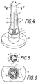
- the arbor 12 has a sleeve body 14 closed at the top.
- the arbor 12 can be interchangeably inserted into the base 11 of the caddy 9.
- he has 12 'claws 12' 'at the lower end of his foot, which engage behind a step in the base 11, as can be seen essentially in FIG. 6.
- a detailed description is unnecessary, since such interchangeable arbors for caddy's have already been described in German patent application P 41 31 527.8.
- a memory chip can be inserted into the cavity formed at the base of the replaceable arbor. Corresponding information about the respective lot can thus be saved, which makes the caddy usable for different lots and the necessary information exchange.
- a flange 12 '' ' secures the base ring 11'.
- Groove-like openings 14 ' are milled into the sleeve body 14, while an additional cutout 14''is provided at the lower end.
- Lamellas 13 pass through the openings 14 'and are also mounted in a plug-in mandrel base body 16 inserted into the sleeve body 14.
- the lamellae 13 have inclined run-up edges 13 'which are intended to facilitate the attachment of the textile bobbin tubes.
- Torsion bar springs 15 are arranged analogously to the first example in longitudinal grooves 19 of the arbor base body 16 and have upper and lower arms 15 'and 15' 'for mutually tensioning the adjacent lamellae 13.
- These widenings 13 ′′ and 13 ′′ ′′ largely fulfill the same function as the extensions 5 ′ and 5 ′′ of the slats 5 in the first exemplary embodiment. They form a stop for the slats 13 on the inside of the sleeve body 14.
- these widenings 13 ′′ and 13 ′′ ′′ still have the function of giving the arms 15 ′ and 15 ′′ a wide guidance in the different positions of the slats 13 . In this way, a larger stroke of the slats 13 within the slat guide grooves 18 in the arbor base body 16 can be realized.
- the plug-on mandrel base body 16 also has an upper and a lower slot star 17 and 17 ′, respectively.
- the slots of these slot stars are wide enough for this.
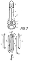
- an elastic body 24 which may for example consist of foam rubber, is provided for tensioning all three slats 26.
- the caddy 20 also has a base plate 21 and a base 22. Above the base 22 is a Arranged sleeve body 23 which has in the region of its upper edge a flange 23 'which is interrupted by openings 23''extending along the sleeve body 23.
- the slats 26 are placed on segments 25, that is, firmly connected to them. These segments 25 have the same curvature on their outer sides as the sleeve body 23 on its inner surface.
- the segments 25 are held against the inner wall of the tube body 23 by the elastic body 24.
- the outer edges of the fins 26 result in the maximum diameter of the arbor.
- the slats 26 are guided through the openings 23, whereby the position of the segments 25 is also clearly determined.
- a plug-on mandrel head 27 is pushed over the flange 23 'of the sleeve body 23.
- the mandrel head 27 has an annular groove 27 'into which the flange 23' engages. This is easily possible since the sleeve body 23 can yield inwards due to the openings 23 ′′.
- This variant of the caddy according to the invention is of a very simple construction, and it is also ensured that a textile sleeve sliding onto the curves 26 'of the slats 26 gradually advances the slats 26 radially inward over their entire length against the resistance of the elastic body 24 shifts.
- the clamping force increases continuously when the textile bobbin tube is pushed on.
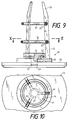
- FIGS. 9 and 10 A fourth variant of the design of a caddy according to the invention is shown in FIGS. 9 and 10.
- a caddy 28 has a base plate 29 and a base 30.
- a bore 29 ' is made through the base 30 and into the base plate 29, into which a bolt 31' of a holder 31 can be inserted.
- This bolt 31 ' can also be secured in the bore 29' by a groove / flange combination.
- Support elements 32 are held in this example by two O-rings 34 and 35, which can be formed from an elastic, preferably metallic material.
- the support elements 32 each have a foot 32 'which is hook-shaped and engages in a groove 31' of the holder 31 which does not extend to the periphery.
- the hook-shaped design of the feet 32 'and 32' '' of the support elements 32 secures the support elements in this area against pivoting outwards. Furthermore, the insertion of the feet 32 'into the grooves 31' ensures that the support elements 32 are held against rotation.
- the O-rings 34 and 35 are inserted into bores 32 ′′ of the support elements 32, which are open on the inside.
- the width of the openings on the inside is less than the diameter of the O-rings 34 and 35.
- the assembly of the Caddy's 28 can be carried out in a very simple manner.
- the support elements 32 are connected to one another by means of the O-rings 34 and 35, the latter being introduced into the bores 32 ′′ and 32 ′′ ′′ via the openings in order to engage there.
- Support elements 32 and O-rings 34 and 35 existing structures placed on the base 30 of the caddy 28.
- the holder 31 is inserted so that the feet 32 'of the support elements 32 are received in the grooves 31'.
- the fastening bolt 31 ' is inserted into the bore 29' and, as described above, snaps into a groove / flange combination in a manner not shown.
- the support elements 32 also have bevels 33 in their upper region, which are intended to facilitate the attachment of a textile bobbin tube.
- bevels 33 in their upper region, which are intended to facilitate the attachment of a textile bobbin tube.
- mandrel head not shown, on the upper ends of the support elements 32 for further stabilization.
Landscapes
- Engineering & Computer Science (AREA)
- Mechanical Engineering (AREA)
- Textile Engineering (AREA)
- Spinning Or Twisting Of Yarns (AREA)
- Storage Of Web-Like Or Filamentary Materials (AREA)
- Replacing, Conveying, And Pick-Finding For Filamentary Materials (AREA)
Applications Claiming Priority (2)
| Application Number | Priority Date | Filing Date | Title |
|---|---|---|---|
| DE4236038A DE4236038A1 (de) | 1992-10-24 | 1992-10-24 | Caddy zum Transport von jeweils einer Textilspule beziehungsweise Textilspulenhülse zu und/oder in einer Textilmaschine |
| DE4236038 | 1992-10-24 |
Publications (2)
| Publication Number | Publication Date |
|---|---|
| EP0595008A1 true EP0595008A1 (fr) | 1994-05-04 |
| EP0595008B1 EP0595008B1 (fr) | 1996-11-20 |
Family
ID=6471328
Family Applications (1)
| Application Number | Title | Priority Date | Filing Date |
|---|---|---|---|
| EP93114827A Expired - Lifetime EP0595008B1 (fr) | 1992-10-24 | 1993-09-15 | Palette pour le transport de bobines textiles ou tubes de bobines textiles à et/ou dans une machine textile |
Country Status (5)
| Country | Link |
|---|---|
| US (1) | US5492280A (fr) |
| EP (1) | EP0595008B1 (fr) |
| JP (1) | JP3527523B2 (fr) |
| CN (1) | CN1036911C (fr) |
| DE (2) | DE4236038A1 (fr) |
Cited By (4)
| Publication number | Priority date | Publication date | Assignee | Title |
|---|---|---|---|---|
| FR2759711A1 (fr) * | 1997-02-17 | 1998-08-21 | Wiele Michel Van De Nv | Douille rotative pour une douille de fil pour un metier a tisser |
| CN104176566A (zh) * | 2014-08-08 | 2014-12-03 | 常州市日发精密机械厂 | 紧固型纺织纱管 |
| US10743723B2 (en) | 2018-09-28 | 2020-08-18 | Gpcp Ip Holdings Llc | Spindle assembly for sheet product dispensers |
| US10952570B2 (en) | 2018-09-28 | 2021-03-23 | Gpcp Ip Holdings Llc | Spindles and dispensers for sheet product |
Families Citing this family (43)
| Publication number | Priority date | Publication date | Assignee | Title |
|---|---|---|---|---|
| DE19547345A1 (de) * | 1995-12-19 | 1997-06-26 | Schlafhorst & Co W | Caddy mit Adapter für unterschiedliche Hülsenlängen |
| CA2247320A1 (fr) * | 1996-02-27 | 1997-09-04 | John Campbell | Chariot de transport |
| US5947409A (en) * | 1996-10-21 | 1999-09-07 | Corrigan, Jr.; Richard W. | Spring finger assembly for engaging a spool |
| US5850986A (en) * | 1997-07-31 | 1998-12-22 | Alexander, Jr.; James E. | Reusable paper-roll core-chuck with interchangeable fins |
| IT1301897B1 (it) | 1998-08-03 | 2000-07-07 | Savio Macchine Tessili Spa | Dispositivo caricatore di spole su un supporto a piattello per illoro trasporto e posizionamento nelle macchine tessili. |
| US6684765B1 (en) | 1999-11-22 | 2004-02-03 | Seagate Technology Llc | Universal shaft design for automatic wiping |
| US6206323B1 (en) | 1999-12-30 | 2001-03-27 | Exim Ltd. | Yarn package holder |
| JP3584368B2 (ja) * | 2000-04-17 | 2004-11-04 | オリオン電機株式会社 | 磁気記録再生装置 |
| US6398434B1 (en) | 2000-10-02 | 2002-06-04 | Richard W. Corrigan, Jr. | Shaft assembly for applying an adjustable load to a thermal print head |
| CA2551077A1 (fr) * | 2003-11-14 | 2005-05-26 | Global Plastics | Ensemble support pour distributeur de papier |
| CH696401A5 (de) * | 2003-12-11 | 2007-05-31 | Rieter Ag Maschf | Transporteinrichtung zum Garntransport. |
| FR2905685B1 (fr) * | 2006-09-08 | 2009-11-06 | Rieter Textile Machinery Fr | Mandrin permettant le positionnement et le maintien d'un tube support |
| US7878116B2 (en) * | 2007-03-16 | 2011-02-01 | Illinois Tool Works Inc. | Methods and apparatus for engaging web-material cores |
| US20090057169A1 (en) * | 2007-08-31 | 2009-03-05 | Benjamin Joseph Kruchoski | Spindle and Spindle Attachments for Coreless and Flexible Core Rolled Tissue Products |
| TWM335472U (en) * | 2008-01-07 | 2008-07-01 | Tsc Auto Id Technology Co Ltd | Carbon ribbon shaft of barcode printer |
| CN101845692A (zh) * | 2010-05-26 | 2010-09-29 | 经纬纺织机械股份有限公司 | 环锭细纱机集体落纱凸盘 |
| CN102433667A (zh) * | 2010-09-29 | 2012-05-02 | 吴江市华英纺织品有限公司 | 纱线卷固定装置 |
| CN102242430B (zh) * | 2011-06-11 | 2013-06-12 | 江阴市华方新技术科研有限公司 | 搓旋法落纱装置 |
| US20130072366A1 (en) * | 2011-09-18 | 2013-03-21 | Steven Lai | Coil-tube chunk for a roll feeder |
| CN102581793B (zh) * | 2012-03-21 | 2014-02-26 | 南通大学 | 一种适用于圆筒类工件的低惯量快速夹具 |
| US8783600B1 (en) * | 2012-07-31 | 2014-07-22 | Richard Myron | Center spreader adapter tool for toilet paper rolls and paper towel rolls that do not have inner cardboard tubes |
| USD703461S1 (en) | 2013-01-24 | 2014-04-29 | Richard Myron | Center spreader adapter tool for toilet paper rolls and paper towel rolls that do not have inner cardboard tubes |
| CN103449246A (zh) * | 2013-09-17 | 2013-12-18 | 张家港优尼克五金工具有限公司 | 一种络筒机用纱筒架 |
| CN103498222A (zh) * | 2013-09-22 | 2014-01-08 | 慈溪在业机械制造有限公司 | 一种高强度嵌入式耐磨凸盘 |
| CN103541062A (zh) * | 2013-09-26 | 2014-01-29 | 吴江伊莱纺织科技有限公司 | 一种纺纱锭子 |
| US20150090835A1 (en) * | 2013-10-02 | 2015-04-02 | Benjamin Bartley Toussaint | Tube Free Toilet Paper Roll Adapter |
| US9770142B2 (en) * | 2013-12-02 | 2017-09-26 | Dispensing Dynamics International, Llc | Multi-piece support for paper roll product |
| DE102014001779A1 (de) * | 2014-02-12 | 2015-08-13 | Atlantic C Handels- Und Beratungs-Gmbh | Vorrichtung zum Lagern von Filamentspulen |
| CN103938349A (zh) * | 2014-03-31 | 2014-07-23 | 吴江明佳织造有限公司 | 纺织用线筒架 |
| CN104088046B (zh) * | 2014-07-24 | 2016-08-24 | 吴江市纺织科技中心有限公司 | 一种胀轴纱锭 |
| USD831706S1 (en) * | 2016-08-16 | 2018-10-23 | Andres Perez | Spool holder |
| CN106283297A (zh) * | 2016-10-10 | 2017-01-04 | 江阴市华方新技术科研有限公司 | 细纱机筒管输送装置 |
| CN106283296A (zh) * | 2016-10-10 | 2017-01-04 | 江阴市华方新技术科研有限公司 | 细纱机筒管座组件 |
| CN108381146B (zh) * | 2018-02-08 | 2019-05-14 | 江苏苏骏纺织有限公司 | 一种纱筒包覆机的导向结构 |
| CN108545539B (zh) * | 2018-03-05 | 2019-10-25 | 青岛华尊机械股份有限公司 | 一种织物面料生产用线筒夹持装置 |
| IT201800004294A1 (it) * | 2018-04-06 | 2019-10-06 | Dispositivo per la movimentazione di bobine | |
| US11825993B2 (en) | 2018-07-09 | 2023-11-28 | Gpcp Ip Holdings Llc | Spindle and cover components for sheet product dispensers and dispenser systems including such components |
| CN109082739B (zh) * | 2018-09-28 | 2024-06-14 | 陕西华燕航空仪表有限公司 | 一种筒管限位装置 |
| DE102018131882A1 (de) | 2018-12-12 | 2020-06-18 | Saurer Spinning Solutions Gmbh & Co. Kg | Spinnkopsaufnahmeeinheit und Spulmaschine |
| CN110453323B (zh) * | 2019-07-26 | 2021-09-21 | 青岛天诺机电有限公司 | 纱锭与纱管的配合结构 |
| CN112193917A (zh) * | 2020-09-28 | 2021-01-08 | 际华三五四二纺织有限公司 | 一种络筒机固定细纱管用的托盘 |
| CN118145412A (zh) * | 2022-12-06 | 2024-06-07 | 无锡捷荣精密机械有限公司 | 一种紧凑型机械式旋转抓取机构及其操作方法 |
| US20240336387A1 (en) * | 2023-04-06 | 2024-10-10 | Mark Mast | Hand wrapper |
Citations (3)
| Publication number | Priority date | Publication date | Assignee | Title |
|---|---|---|---|---|
| DE7301717U (de) * | 1973-01-18 | 1973-05-10 | Licentia Gmbh | Kopsbehälter |
| DE4016466A1 (de) * | 1990-05-22 | 1991-11-28 | Schlafhorst & Co W | Textilmaschine, insbesondere automatische spulmaschine, mit einem transportsystem, in dem voneinander unabhaengige paletten zirkulieren |
| DE4110284A1 (de) * | 1991-03-28 | 1992-10-01 | Schlafhorst & Co W | Palette, die jeweils eine textilspule aufrechtstehend waehrend des transportes und in bearbeitungsstationen einer textilmaschine traegt |
Family Cites Families (17)
| Publication number | Priority date | Publication date | Assignee | Title |
|---|---|---|---|---|
| DE500052C (de) * | 1926-09-30 | 1930-06-17 | Barber Colman Co | Aufsteckdorn fuer Spulmaschinen |
| US3006565A (en) * | 1960-06-30 | 1961-10-31 | Eugene V Pelletier | Bobbin clutch |
| US3292874A (en) * | 1964-07-30 | 1966-12-20 | Herbert M Tinkham | Roll holder |
| DE1278231B (de) * | 1966-09-22 | 1968-09-19 | Zeiss Ikon Ag | Filmspulenzapfen |
| US3617011A (en) * | 1969-02-13 | 1971-11-02 | Elitex Zavody Textilniho | Device for the automatic fastening of supply yarn tubes of various diameters and for their changing in textile machines |
| GB1383775A (en) * | 1972-05-31 | 1974-02-12 | French & Sons Thomas | Form package holders |
| US3811636A (en) * | 1972-12-05 | 1974-05-21 | F Muchnick | Yarn bobbin support device |
| DE2405796A1 (de) * | 1974-02-07 | 1975-08-14 | Mayer Textilmaschf | Halter fuer kreuzspulen |
| GB1524967A (en) * | 1974-11-13 | 1978-09-13 | Sissons A J | Roll-handling equipment |
| JPS5859167A (ja) * | 1981-09-25 | 1983-04-08 | Murata Mach Ltd | 管糸搬送システム |
| JPS6023260A (ja) * | 1983-07-19 | 1985-02-05 | Murata Mach Ltd | 糸端の口出し装置 |
| JPH0780631B2 (ja) * | 1988-03-17 | 1995-08-30 | 村田機械株式会社 | 巻取方法 |
| JPH038678A (ja) * | 1989-06-05 | 1991-01-16 | Hitachi Elevator Eng & Service Co Ltd | エレベータの監視装置 |
| DE3925987A1 (de) * | 1989-08-05 | 1991-02-07 | Schlafhorst & Co W | Verfahren und vorrichtung zum drehen eines kopses, der aufrechtstehend auf dem aufsteckdorn einer palette aufgesteckt ist |
| DE4015173A1 (de) * | 1990-05-11 | 1991-11-14 | Schlafhorst & Co W | Transportsystem fuer auf unabhaengige einzeltraeger senkrecht aufgesetzte spulen oder spulenhuelsen zwischen in der hoehe unterschiedlichen transportebenen |
| DE4121244A1 (de) * | 1991-06-27 | 1993-01-07 | Basf Magnetics Gmbh | Wickelkern-spannvorrichtung |
| DE4131527A1 (de) * | 1991-09-21 | 1993-03-25 | Schlafhorst & Co W | Caddy fuer den voneinander unabhaengigen einzeltransport von kopsen und kopshuelsen in einem transportsystem einer textilmaschine |
-
1992
- 1992-10-24 DE DE4236038A patent/DE4236038A1/de not_active Withdrawn
-
1993
- 1993-09-15 DE DE59304535T patent/DE59304535D1/de not_active Expired - Fee Related
- 1993-09-15 EP EP93114827A patent/EP0595008B1/fr not_active Expired - Lifetime
- 1993-10-21 JP JP26345693A patent/JP3527523B2/ja not_active Expired - Fee Related
- 1993-10-22 CN CN93119152A patent/CN1036911C/zh not_active Expired - Fee Related
- 1993-10-25 US US08/142,179 patent/US5492280A/en not_active Expired - Fee Related
Patent Citations (3)
| Publication number | Priority date | Publication date | Assignee | Title |
|---|---|---|---|---|
| DE7301717U (de) * | 1973-01-18 | 1973-05-10 | Licentia Gmbh | Kopsbehälter |
| DE4016466A1 (de) * | 1990-05-22 | 1991-11-28 | Schlafhorst & Co W | Textilmaschine, insbesondere automatische spulmaschine, mit einem transportsystem, in dem voneinander unabhaengige paletten zirkulieren |
| DE4110284A1 (de) * | 1991-03-28 | 1992-10-01 | Schlafhorst & Co W | Palette, die jeweils eine textilspule aufrechtstehend waehrend des transportes und in bearbeitungsstationen einer textilmaschine traegt |
Cited By (8)
| Publication number | Priority date | Publication date | Assignee | Title |
|---|---|---|---|---|
| FR2759711A1 (fr) * | 1997-02-17 | 1998-08-21 | Wiele Michel Van De Nv | Douille rotative pour une douille de fil pour un metier a tisser |
| BE1010928A3 (nl) * | 1997-02-17 | 1999-03-02 | Wiele Michel Van De Nv | Draaihuls voor een huls met garen voor een weefmachine. |
| US6119975A (en) * | 1997-02-17 | 2000-09-19 | N.V. Michael Van De Wiele | Rotating sleeve for a sleeve with yarn for a weaving machine |
| CN104176566A (zh) * | 2014-08-08 | 2014-12-03 | 常州市日发精密机械厂 | 紧固型纺织纱管 |
| US10743723B2 (en) | 2018-09-28 | 2020-08-18 | Gpcp Ip Holdings Llc | Spindle assembly for sheet product dispensers |
| US10952570B2 (en) | 2018-09-28 | 2021-03-23 | Gpcp Ip Holdings Llc | Spindles and dispensers for sheet product |
| US11311152B2 (en) | 2018-09-28 | 2022-04-26 | Gpcp Ip Holdings Llc | Spindle assembly for sheet product dispensers |
| US11723496B2 (en) | 2018-09-28 | 2023-08-15 | Gpcp Ip Holdings Llc | Spindles and dispensers for sheet product |
Also Published As
| Publication number | Publication date |
|---|---|
| DE4236038A1 (de) | 1994-04-28 |
| JPH06211432A (ja) | 1994-08-02 |
| JP3527523B2 (ja) | 2004-05-17 |
| US5492280A (en) | 1996-02-20 |
| EP0595008B1 (fr) | 1996-11-20 |
| CN1036911C (zh) | 1998-01-07 |
| DE59304535D1 (de) | 1997-01-02 |
| CN1088539A (zh) | 1994-06-29 |
Similar Documents
| Publication | Publication Date | Title |
|---|---|---|
| EP0595008A1 (fr) | Palette pour le transport de bobines textiles ou tubes de bobines textiles à et/ou dans une machine textile | |
| EP0628737B1 (fr) | Dispositif de fixation | |
| WO2012098001A2 (fr) | Bobine destinée à recevoir un produit à enrouler et système de séparation de bobine | |
| EP0201794A2 (fr) | Corps de bobine formé de deux composants | |
| DE102014109546A1 (de) | Spannfutter und Spannmittel mit Schnellwechselfunktion | |
| EP2774469A1 (fr) | Support de bobine pour une bobine de fil de coupe | |
| DE2046272B2 (de) | ^kupplungsvorrichtung für die Halterung der dünnen Brennstoffstäbe in einem Kernreaktor-Brennelement | |
| EP0380930A1 (fr) | Système de transport suspendu | |
| EP0063783A1 (fr) | Dispositif téléscopique de longueur ajustable | |
| DE19700185A1 (de) | Spule zur Aufnahme von wickelbarem Strangmaterial | |
| DE2824330C3 (de) | Spulenanordnung für Bandgeräte | |
| EP0048912A1 (fr) | Support d'enroulement pour recevoir des fils | |
| DE4016466A1 (de) | Textilmaschine, insbesondere automatische spulmaschine, mit einem transportsystem, in dem voneinander unabhaengige paletten zirkulieren | |
| DE3226455C1 (de) | Einrichtung zum Austausch von Gegenstaenden,insbesondere Schreibstiften | |
| DE29702673U1 (de) | Federspanner zum Spannen von Schraubenfedern mit zwei Druckplatten | |
| EP0418418B1 (fr) | Dispositif de transport dans un métier à filer | |
| DE60213702T2 (de) | Garnaufwickelhülse | |
| DE3034993A1 (de) | Fadenzufuehreinrichtung fuer rundstrickmaschinen | |
| DE69104691T2 (de) | Sicherheitsvorrichtung für eine Vorspinnmaschine, die mit einer automatischen Abnehmervorrichtung versehen ist. | |
| DE4340031A1 (de) | Kopplungs- und Haltevorrichtung für Vorspinn-Spulen | |
| DE10038788B4 (de) | Halterung für Abspulrollen | |
| DE4444985A1 (de) | Vorrichtung zum Fixieren von Vorratsspulen auf einem sich drehenden Spulenaufnahmeteil | |
| DE4227302A1 (de) | Textilmaschine, insbesondere automatische Spulmaschine mit einem Transportsystem, in dem voneinander unabhängige Caddy`s zirkulieren | |
| EP3677712B1 (fr) | Support de bobine de filage pour une machine de tordage | |
| DE4226105A1 (de) | Caddy zum Transport von jeweils einer Textilspule zu und/oder in einer Textilmaschine |
Legal Events
| Date | Code | Title | Description |
|---|---|---|---|
| PUAI | Public reference made under article 153(3) epc to a published international application that has entered the european phase |
Free format text: ORIGINAL CODE: 0009012 |
|
| AK | Designated contracting states |
Kind code of ref document: A1 Designated state(s): CH DE IT LI |
|
| 17P | Request for examination filed |
Effective date: 19940908 |
|
| 17Q | First examination report despatched |
Effective date: 19950407 |
|
| GRAG | Despatch of communication of intention to grant |
Free format text: ORIGINAL CODE: EPIDOS AGRA |
|
| GRAH | Despatch of communication of intention to grant a patent |
Free format text: ORIGINAL CODE: EPIDOS IGRA |
|
| ITF | It: translation for a ep patent filed | ||
| GRAH | Despatch of communication of intention to grant a patent |
Free format text: ORIGINAL CODE: EPIDOS IGRA |
|
| GRAA | (expected) grant |
Free format text: ORIGINAL CODE: 0009210 |
|
| AK | Designated contracting states |
Kind code of ref document: B1 Designated state(s): CH DE IT LI |
|
| REF | Corresponds to: |
Ref document number: 59304535 Country of ref document: DE Date of ref document: 19970102 |
|
| PLBE | No opposition filed within time limit |
Free format text: ORIGINAL CODE: 0009261 |
|
| 26N | No opposition filed | ||
| PGFP | Annual fee paid to national office [announced via postgrant information from national office to epo] |
Ref country code: CH Payment date: 20040903 Year of fee payment: 12 |
|
| PG25 | Lapsed in a contracting state [announced via postgrant information from national office to epo] |
Ref country code: LI Free format text: LAPSE BECAUSE OF NON-PAYMENT OF DUE FEES Effective date: 20050930 Ref country code: CH Free format text: LAPSE BECAUSE OF NON-PAYMENT OF DUE FEES Effective date: 20050930 |
|
| REG | Reference to a national code |
Ref country code: CH Ref legal event code: PL |
|
| PGFP | Annual fee paid to national office [announced via postgrant information from national office to epo] |
Ref country code: IT Payment date: 20060930 Year of fee payment: 14 |
|
| PGFP | Annual fee paid to national office [announced via postgrant information from national office to epo] |
Ref country code: DE Payment date: 20080930 Year of fee payment: 16 |
|
| PG25 | Lapsed in a contracting state [announced via postgrant information from national office to epo] |
Ref country code: IT Free format text: LAPSE BECAUSE OF NON-PAYMENT OF DUE FEES Effective date: 20070915 |
|
| PG25 | Lapsed in a contracting state [announced via postgrant information from national office to epo] |
Ref country code: DE Free format text: LAPSE BECAUSE OF NON-PAYMENT OF DUE FEES Effective date: 20100401 |