EP0596163A1 - Autocuisseur à soupape de sécurité et de purge - Google Patents
Autocuisseur à soupape de sécurité et de purge Download PDFInfo
- Publication number
- EP0596163A1 EP0596163A1 EP19920309998 EP92309998A EP0596163A1 EP 0596163 A1 EP0596163 A1 EP 0596163A1 EP 19920309998 EP19920309998 EP 19920309998 EP 92309998 A EP92309998 A EP 92309998A EP 0596163 A1 EP0596163 A1 EP 0596163A1
- Authority
- EP
- European Patent Office
- Prior art keywords
- release valve
- safety release
- dual
- stem
- lid
- Prior art date
- Legal status (The legal status is an assumption and is not a legal conclusion. Google has not performed a legal analysis and makes no representation as to the accuracy of the status listed.)
- Granted
Links
Images

Classifications
-
- A—HUMAN NECESSITIES
- A47—FURNITURE; DOMESTIC ARTICLES OR APPLIANCES; COFFEE MILLS; SPICE MILLS; SUCTION CLEANERS IN GENERAL
- A47J—KITCHEN EQUIPMENT; COFFEE MILLS; SPICE MILLS; APPARATUS FOR MAKING BEVERAGES
- A47J27/00—Cooking-vessels
- A47J27/08—Pressure-cookers; Lids or locking devices specially adapted therefor
- A47J27/09—Safety devices
-
- F—MECHANICAL ENGINEERING; LIGHTING; HEATING; WEAPONS; BLASTING
- F16—ENGINEERING ELEMENTS AND UNITS; GENERAL MEASURES FOR PRODUCING AND MAINTAINING EFFECTIVE FUNCTIONING OF MACHINES OR INSTALLATIONS; THERMAL INSULATION IN GENERAL
- F16K—VALVES; TAPS; COCKS; ACTUATING-FLOATS; DEVICES FOR VENTING OR AERATING
- F16K17/00—Safety valves; Equalising valves, e.g. pressure relief valves
- F16K17/36—Safety valves; Equalising valves, e.g. pressure relief valves actuated in consequence of extraneous circumstances, e.g. shock, change of position
- F16K17/38—Safety valves; Equalising valves, e.g. pressure relief valves actuated in consequence of extraneous circumstances, e.g. shock, change of position of excessive temperature
- F16K17/383—Safety valves; Equalising valves, e.g. pressure relief valves actuated in consequence of extraneous circumstances, e.g. shock, change of position of excessive temperature the valve comprising fusible, softening or meltable elements, e.g. used as link, blocking element, seal, closure plug
-
- Y—GENERAL TAGGING OF NEW TECHNOLOGICAL DEVELOPMENTS; GENERAL TAGGING OF CROSS-SECTIONAL TECHNOLOGIES SPANNING OVER SEVERAL SECTIONS OF THE IPC; TECHNICAL SUBJECTS COVERED BY FORMER USPC CROSS-REFERENCE ART COLLECTIONS [XRACs] AND DIGESTS
- Y10—TECHNICAL SUBJECTS COVERED BY FORMER USPC
- Y10T—TECHNICAL SUBJECTS COVERED BY FORMER US CLASSIFICATION
- Y10T137/00—Fluid handling
- Y10T137/1624—Destructible or deformable element controlled
- Y10T137/1797—Heat destructible or fusible
- Y10T137/1804—With second sensing means
-
- Y—GENERAL TAGGING OF NEW TECHNOLOGICAL DEVELOPMENTS; GENERAL TAGGING OF CROSS-SECTIONAL TECHNOLOGIES SPANNING OVER SEVERAL SECTIONS OF THE IPC; TECHNICAL SUBJECTS COVERED BY FORMER USPC CROSS-REFERENCE ART COLLECTIONS [XRACs] AND DIGESTS
- Y10—TECHNICAL SUBJECTS COVERED BY FORMER USPC
- Y10T—TECHNICAL SUBJECTS COVERED BY FORMER US CLASSIFICATION
- Y10T137/00—Fluid handling
- Y10T137/1624—Destructible or deformable element controlled
- Y10T137/1797—Heat destructible or fusible
- Y10T137/1812—In fluid flow path
Definitions
- This invention relates to a novel dual function, dual metal, thermally fusible type, Safety Release Valve for use in domestic pressure cookers.
- the two valves referred above, are the Primary Release Valve and the Secondary Release Valve.
- the Primary Release Valve is usually a dead weight type of valve, closing an orifice by means of a conical pin, engaging the orifice.
- the dead weight determines the normal cooking pressure which is usually 15 Ibs per sq. in.
- the dead weight of the Primary Release Valve is also referred to as Vent Weight, because it vents the excess steam.
- the Secondary Release Valve is expected to work only in an emergency, when the Primary Release Valve has failed to function for some reason, for example, the food particles can clog the steam-release hole of the Primary Release Valve.
- the Secondary Release Valves are usually of three types.
- one type of Secondary Release Valve which is of the non-fusible repeat functioning type, the pressure exerted by a spring on the valve stem, controls the pressure of steam under conditions of emergency release.
- the Secondary Release Valve In a second type of the Secondary Release Valve, it has a fusible low melting alloy, encased in a non-fusible metal retainer of good heat conducting material like aluminium.
- a fusible low melting alloy encased in a non-fusible metal retainer of good heat conducting material like aluminium.
- the Steam pressure builds up to increasing value and the temperature of the steam also increases correspondingly; and, at a particular stage of steam pressure, the temperature is sufficiently high, so as to cause the melting of fusible metal alloy.
- the alloy melts, creates an opening in the lid, and through the opening, steam under excess pressure is safely let out.
- the fusible metal alloy safety valve has to be replaced by a new fusible Secondary Release Valve.
- the Safety Release Valve is made up of two parts, viz. the safety fuse retainer and a holding nut.
- the safety fuse retainer is fastened to the lid of the pressure cooker by means of holding nut.
- the safety fuse retainer has at its centre, the low melting fusible alloy ( Figure 1).
- the retainer and the nut are usually made of aluminium, to pick up the temperature of the steam rapidly and transmit it to the fusible alloy faster.
- the safety fuse retainer and the nut are clamped tight to the lid so that steam cannot escape in any manner at the joint.
- the metallic part is a "pintle” made of fusible low melting alloy. It is suspended from a hole in a thick rubber housing (the non-metallic material). The rubber housing is slipped into a hole, (and held in position) on the lid of the pressure cooker. When excessive steam pressure builds up, the rubber housing ejects out of the lid, exposing an orifice in the lid and steam is allowed to escape.
- the fusible metal "pintle” has a head and conical bulbous portion connected by a narrow neck. The head prevents the "pintle” from falling into the cooker.
- the lid of the pressure cooker is closed, and heat is applied.
- the manufacturers of all pressure cookers advise the users to let out steam and air, through the orifice meant for the dead weight of the Primary Release Valve, for a while and then place the dead weight.
- the reasons for this instruction are two: By following the instruction, the user first ensures that the Primary Release orifice is clear and there is no danger of prior choking by food particles.
- the temperature of water inside the pressure cooker gradually rises to 100 ° C and beyond.
- the steam pressure, in the empty space inside the pressure cooker continues to build up.
- the pressure of the air inside the empty space also increases; thus at any point of time, for a given temperature inside the pressure cooker, the pressure would be the sum total of the steam pressure and the air pressure taken separately. If for any reason, the Primary Release Valve fails to function, the pressure and temperature of the steam would increase until the temperature sensitive fusible metal alloy of the Secondary Release Valve melts, and releases excess pressure.
- the fusible metal alloy is sensitive to steam temperature and not to its pressure, there is the liklihood of the cooker being subjected to higher pressures than expected, the excess pressure over the steam pressure being contributed by the individual pressure of air.
- the performance of the thermally fusible safety valve gets vitiated by the presence of air and the error can be as much as 10 psi, decreasing the factor of safety in mechanical strength, provided in the Design of the pressure cooker.
- a novel dual functioning, dual metal, Safety Release Valve which comprises a fusible metallic material held within the bore of a metallic retainer member, the stem of the said metallic retainer being adapted to be loosely and angularly held by a holding member, to an opening in the lid of the pressure cooker, the said stem also having a thin washer made of non-metallic resilient material adapted to seal under steam pressure, the opening in the lid of the pressure cooker, automatically, after substantially all the air is vented.
- the fusible metallic material is made of conventional low temperature fusible metal alloys.
- the fusible material is held in the form of a plug at the lower end of the vertical bore in the metallic retainer member.
- the holding member is adapted to be engaged externally to the lid of the pressure cooker on the protruding portion of the stem of the metallic retainer.
- the lower body of the metallic retainer is provided with an undercut - cut portion externally adapted to provide a seat for the non-metallic resilient washer.
- the non-metallic resilient washer is made of nitrile rubber or other similar heat resilient elastic material.
- the Safety Fuse comprises a fusible material 2 provided in the bore of a safety fuse retainer 10.
- the retainer 10 has an extended lower flange 9 accommodating the fusible material 2 within the bore 10A.
- the Safety fuse retainer is introduced from underside of the lid 11 through the hole 5 and is secured tightly to the lid by means of holding nut 12 using washer 13.
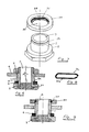
- FIG 2 a cross section of part of the lid is shown carrying the conventional Primary Release Valve and the novel Safety Release Valve made of dual metal.
- the novel Safety Release Valve is shown in a suspended manner while in Figure 3, the same fuse is shown in the working condition of the cooker under pressure.
- the novel dual function, dual metal, thermally fusible Safety Release Valve will be seen to consist of a hollow metal retainer 1 with a central vertical bore 7. At the lower end of the vertical bore, there is provided a temperature sensitive thermally fusible safety fuse 2 which is made of a conventional low temperature melting metal alloy. The fuse is held in the form of a plug having extension 2A held within a socket like provision 1A of the retainer 1.
- the top end of the safety fuse metal retainer 1 is externally threaded to a limited extent so as to engage an internally threaded nut 3, such that the lower portion of the safety fuse retainer is loosely held in a suspended manner on the lid 4 of the pressure cooker through the hole 5 provided in the lid. It is also possible, to suspend the Safety fuse retainer by other means, such as by a cross - pin instead of the nut.
- the lower end of the safety fuse retainer is provided with an under - cut portion 6A into which is securely held a washer 6 made of resilient material, such as, nitrile rubber or other similar heat resistant elastic material.
- the holding unit 1 is provided with a narrow taper 8 externally tapering towards the top leaving a clearance between the top of the taper and the hole in the lid in the free suspended condition.
- the seal is seated below the lower base of the taper in the under-cut 6A as before.
- the stem will gradually close the opening during lift of the retainer and there will be uniform pressure balance.
- the clearance between the stem and the hole in the lid gets gradually decreased and the pressure build up is faster due to reduced gap for escape of steam as compared to a straight exterior stem.
- the air ventile is held to the hole in the lid of the cooker in a freely suspended manner by means of a holding sleeve - 3A. , which replaces the holding nut 3.
- the sleeve is made specially for this purpose from a suitable flat metallic member having a central bore 3D whose diameter is slightly larger than the outer diameter of the stem of the air - ventile such that it can be slipped on the outer surface of the stem 1.
- the inner wall of the holding sleeve is provided with cylindrical groove 3B so as to accomodate a resilient clip 3C or holding spring 3C which has cut open ends as shown in figure 8 .
- the distance between the inner edges of the clip is marginally less than the outer diameter of the stem.
- the straight leg portions 3C, and 3C 2 of the clip which are separated by a distance less than the diameter of the groove, and also slightly less than the outer diameter of the stem of the spindle, these legs tend to expand when the stem is introduced between these legs and the stem can be slipped through.
- the outer surface of the stem is provided with a circular groove 1A whose diameter is about the same as the separating distance between the legs such that these legs snap into the groove and are held therein thereby arresting further insertion of the stem between the legs of the clip.
- the clip is free of the stem.
- the holding nut 3 ( or cross - pin ) is first removed and the top end of the Safety fuse retainer is introduced through the hole 5 of the lid from the underside of the lid.
- the safety fuse retainer already holds the safety fuse 2 and the resilient washer 6 in position at its lower end in the internal bore 7 and on the outside under-cut 6A respectively.
- the holding nut is then threaded on to the upper end of the safety fuse retainer or the cross - pin is put in position in suitable aligned holes in the top of the stem.
- the safety fuse retainer is held floatingly and in a suspended manner in the hole of the lid.
- the holding sleeve 3A is first removed by exerting a slight pulling pressure and the top end of the safety fuse retainer is introduced through the hole 5 of the lid from the underside of the lid.
- the safety fuse retainer already holds the safety fuse 2 and the resilient washer 6 in position at its lower end in the internal bore 7 and on the outside under-cut 6A respectively.
- the holding sleeve is then placed on the top of the stem and gently pressed, preferably slightly slantingly.
- the top of the stem is located between the two legs.
- the holding sleeve gently slips through until the two legs 3Ci ,3C 2 of the clip engage the outer groove 7A on the stem.
- the groove 7A By suitably position the groove 7A , the air ventile will remain in a suspended state as the earlier one .
- the external diameter of the safety fuse retainer is smaller to a predetermined degree than the diameter of the hole in the lid. This is to give an intended annular gap for the escape of steam and air.
- the Safety Valve is called a dual metal, dual function valve for the following reasons.
- the holding unit is made of a non - fusible metal like aluminium and in the central bore there is provided a fusible plug made of known fusible metal alloy.
- Valve is intended to first let out substantially all the trapped air and some steam as a mixture in the initial stages in the suspended stage and then in the sealed stage function as the normal safety valve due to the melting of the alloy in the instance of excess pressure of steam and steam temperature.
- the holding nut sits square on the external surface of the lid, on the slightly depressed and flattened portion of the hole in the lid. Due to the curvature of the lid, the Safety Release Valve assumes a dangling position, somewhat slanted to the vertical position.
- the fusible material i. e. the Safety fuse 2 ( Figure 5) gets overheated and melts in the normal manner, thereby opening the central bore 7 of the safety fuse retainer 1, thus enabling the safe exit of steam.
- the Safety Release Valve functions as an air- venting valve and in the later stages of operation, it functions as a thermally fusible safety fuse. The dual functions are thus achieved by this dual metal valve.
- Another factor responsible for a satisfactory functioning of the thermally fusible Safety Release Valve of the invention is the dead weight of the Safety Release Valve and the extent of lift that is available before the hole in the lid could be sealed.
- a predetermined extent of lift in the range of 1 to 3 mm is essential. Otherwise, a lesser extent of lift will seal the hole prior to air being completely expelled. If the lift is more than the predetermined range, either it takes a longer duration for sealing the hole when the pressure cooker is in operation, or the hole does not get sealed at all.
- the dead weight of the thermally fusible Safety Release Valve of the invention is too less the hole gets sealed earlier before all the air could be vented. If the dead weight is too much, either it takes a longer duration for sealing the hole or the hole does not get sealed at all. Dead weight which depends on "lift" and stem diameter, and annular clearance, etc. has to be adjusted in such a way that the rubber washer of the safety fuse retainer, seals the annular gap in the approximate pressure range 0.1 to 0.8 psi.
- the central/longitudinal axis of the same should be inclined to the vertical axis of the cooker by an amount of angle a ranging from 3° to 18° because when such an angle is maintained, the resultant force of the issuing steam takes the right time to bodily lift the valve when substantially all the air has been removed.
- angle a ranging from 3° to 18° because when such an angle is maintained, the resultant force of the issuing steam takes the right time to bodily lift the valve when substantially all the air has been removed.
- angle a ranging from 3° to 18°
Landscapes
- Engineering & Computer Science (AREA)
- General Engineering & Computer Science (AREA)
- Mechanical Engineering (AREA)
- Food Science & Technology (AREA)
- Cookers (AREA)
- Safety Valves (AREA)
Priority Applications (5)
| Application Number | Priority Date | Filing Date | Title |
|---|---|---|---|
| DE69221624T DE69221624T2 (de) | 1992-11-02 | 1992-11-02 | Entlüftungs- und Sicherheitsventil für Dampfdruckkochtöpfe |
| EP19920309998 EP0596163B1 (fr) | 1992-11-02 | 1992-11-02 | Autocuisseur à soupape de sécurité et de purge |
| ES92309998T ES2107508T3 (es) | 1992-11-02 | 1992-11-02 | Nueva valvula de alivio para ollas a presion y ollas a presion que la tienen. |
| AU28137/92A AU662935B2 (en) | 1992-11-02 | 1992-11-05 | Air ventile for pressure cookers |
| US07/991,645 US5269336A (en) | 1992-11-02 | 1992-12-16 | Air ventile for pressure cookers and pressure cookers having the same |
Applications Claiming Priority (3)
| Application Number | Priority Date | Filing Date | Title |
|---|---|---|---|
| EP19920309998 EP0596163B1 (fr) | 1992-11-02 | 1992-11-02 | Autocuisseur à soupape de sécurité et de purge |
| AU28137/92A AU662935B2 (en) | 1992-11-02 | 1992-11-05 | Air ventile for pressure cookers |
| US07/991,645 US5269336A (en) | 1992-11-02 | 1992-12-16 | Air ventile for pressure cookers and pressure cookers having the same |
Publications (2)
| Publication Number | Publication Date |
|---|---|
| EP0596163A1 true EP0596163A1 (fr) | 1994-05-11 |
| EP0596163B1 EP0596163B1 (fr) | 1997-08-13 |
Family
ID=27153142
Family Applications (1)
| Application Number | Title | Priority Date | Filing Date |
|---|---|---|---|
| EP19920309998 Expired - Lifetime EP0596163B1 (fr) | 1992-11-02 | 1992-11-02 | Autocuisseur à soupape de sécurité et de purge |
Country Status (5)
| Country | Link |
|---|---|
| US (1) | US5269336A (fr) |
| EP (1) | EP0596163B1 (fr) |
| AU (1) | AU662935B2 (fr) |
| DE (1) | DE69221624T2 (fr) |
| ES (1) | ES2107508T3 (fr) |
Cited By (2)
| Publication number | Priority date | Publication date | Assignee | Title |
|---|---|---|---|---|
| EP1277427A1 (fr) * | 2001-07-20 | 2003-01-22 | Seb S.A. | Autocuiseur comportant une soupape d'evacuation d'air calibre |
| WO2006086440A3 (fr) * | 2005-02-08 | 2006-10-26 | Fry Metals Inc | Bouchon de surete thermosensible et procede de fabrication |
Families Citing this family (11)
| Publication number | Priority date | Publication date | Assignee | Title |
|---|---|---|---|---|
| US5683102A (en) * | 1996-04-08 | 1997-11-04 | Morton International, Inc. | Ported passenger airbag module can |
| AUPP942099A0 (en) * | 1999-03-24 | 1999-04-15 | Vos Industries Limited | Improvements to cooking apparatus |
| US20080066805A1 (en) * | 2006-09-20 | 2008-03-20 | Gm Global Technology Operations, Inc. | Pressure tank system with heat conducting layer |
| US8186921B2 (en) * | 2006-12-08 | 2012-05-29 | General Plug & Manufacturing Company | Drain plug |
| US8833591B2 (en) * | 2012-03-22 | 2014-09-16 | Steve Kotevski | Ammunition can with safety valve |
| CN102401232B (zh) * | 2011-09-29 | 2014-02-12 | 郑州大学 | 沼气节气装置 |
| US9970560B2 (en) * | 2015-07-16 | 2018-05-15 | Goodrich Corporation | Wheel and tire sealing system with fuse plug |
| WO2019075455A1 (fr) * | 2017-10-13 | 2019-04-18 | National Presto Industries, Inc. | Dispositif de mise en conserve électrique sous pression à commande numérique |
| CN112216313B (zh) * | 2020-09-16 | 2022-04-19 | 上海三利数字技术有限公司 | 数据灾备存储装置及载具 |
| WO2024103484A1 (fr) * | 2022-11-16 | 2024-05-23 | 上海三利数字技术有限公司 | Noyau de soupape, soupape de surpression, contenant interne de stockage de données ignifuge et dispositif de stockage de données ignifuge |
| CN117002855B (zh) * | 2023-07-11 | 2026-01-09 | 欧水胜 | 一种具有气压增压功能的油桶 |
Citations (7)
| Publication number | Priority date | Publication date | Assignee | Title |
|---|---|---|---|---|
| GB619002A (en) * | 1946-08-28 | 1949-03-02 | Nat Pressure Cooking Company | Improvement in pressure gauges for use on pressure vessels |
| GB708882A (en) * | 1952-05-16 | 1954-05-12 | Midland Metal Spinning Company | Safety devices for pressure cookers and like pressure vessels |
| DE926029C (de) * | 1951-12-22 | 1955-04-04 | Metall Werk Meschede G M B H | Schutzvorrichtung fuer UEberdrucksicherungen an Dampfdruck-Kochtoepfen |
| FR1324454A (fr) * | 1962-04-06 | 1963-04-19 | Fissler Kg R | Soupape de sécurité et de mise à l'air pour casseroles sous pression |
| DE1925264A1 (de) * | 1969-05-17 | 1970-11-19 | Fissler Kg R | Sicherheitsventil fuer Dampfdruckkochtoepfe |
| FR2502929A1 (fr) * | 1981-04-01 | 1982-10-08 | Fissler Ges Gmbh | Dispositif de verrouillage de couvercle et de detente de la pression d'un autocuiseur |
| DE3330656A1 (de) * | 1983-08-25 | 1985-03-14 | Alfa Institut für hauswirtschaftliche Produkt- und Verfahrens-Entwicklung GmbH, 6228 Eltville | Entlueftungs- und druckentlastungseinrichtung an einem dampfdruckkochtopf |
Family Cites Families (11)
| Publication number | Priority date | Publication date | Assignee | Title |
|---|---|---|---|---|
| US1093576A (en) * | 1913-03-13 | 1914-04-14 | Carrie Emma Owen | Safety-closure. |
| US2188735A (en) * | 1937-01-02 | 1940-01-30 | Advance Aluminum Castings Corp | Pressure cooker |
| US2357620A (en) * | 1941-04-28 | 1944-09-05 | Phillips Petroleum Co | Closure unit for containers |
| US2619982A (en) * | 1946-06-06 | 1952-12-02 | Proctor Electric Co | Pressure relief plug for pressure cookers |
| US2580340A (en) * | 1947-10-29 | 1951-12-25 | Ekco Products Company | Safety plug for pressure cookers |
| US2908288A (en) * | 1955-04-13 | 1959-10-13 | Crane Co | Calibrated relief valve |
| GB1412896A (en) * | 1973-11-06 | 1975-11-05 | Sugimura N | Pressure container |
| ZA776487B (en) * | 1977-04-29 | 1978-08-30 | Nat Presto Ind | Pressure cooker |
| US4143787A (en) * | 1978-06-15 | 1979-03-13 | National Presto Industries, Inc. | Captivated over-pressure relief air vent assembly |
| US4796776A (en) * | 1987-02-19 | 1989-01-10 | Northland Aluminum Products, Inc. | Pressure cooker for microwave ovens |
| ES1011685Y (es) * | 1989-10-16 | 1990-11-16 | Fagor, S. Coop. Ltda. | Olla a presion perfeccionada. |
-
1992
- 1992-11-02 ES ES92309998T patent/ES2107508T3/es not_active Expired - Lifetime
- 1992-11-02 EP EP19920309998 patent/EP0596163B1/fr not_active Expired - Lifetime
- 1992-11-02 DE DE69221624T patent/DE69221624T2/de not_active Expired - Fee Related
- 1992-11-05 AU AU28137/92A patent/AU662935B2/en not_active Ceased
- 1992-12-16 US US07/991,645 patent/US5269336A/en not_active Expired - Fee Related
Patent Citations (7)
| Publication number | Priority date | Publication date | Assignee | Title |
|---|---|---|---|---|
| GB619002A (en) * | 1946-08-28 | 1949-03-02 | Nat Pressure Cooking Company | Improvement in pressure gauges for use on pressure vessels |
| DE926029C (de) * | 1951-12-22 | 1955-04-04 | Metall Werk Meschede G M B H | Schutzvorrichtung fuer UEberdrucksicherungen an Dampfdruck-Kochtoepfen |
| GB708882A (en) * | 1952-05-16 | 1954-05-12 | Midland Metal Spinning Company | Safety devices for pressure cookers and like pressure vessels |
| FR1324454A (fr) * | 1962-04-06 | 1963-04-19 | Fissler Kg R | Soupape de sécurité et de mise à l'air pour casseroles sous pression |
| DE1925264A1 (de) * | 1969-05-17 | 1970-11-19 | Fissler Kg R | Sicherheitsventil fuer Dampfdruckkochtoepfe |
| FR2502929A1 (fr) * | 1981-04-01 | 1982-10-08 | Fissler Ges Gmbh | Dispositif de verrouillage de couvercle et de detente de la pression d'un autocuiseur |
| DE3330656A1 (de) * | 1983-08-25 | 1985-03-14 | Alfa Institut für hauswirtschaftliche Produkt- und Verfahrens-Entwicklung GmbH, 6228 Eltville | Entlueftungs- und druckentlastungseinrichtung an einem dampfdruckkochtopf |
Cited By (6)
| Publication number | Priority date | Publication date | Assignee | Title |
|---|---|---|---|---|
| EP1277427A1 (fr) * | 2001-07-20 | 2003-01-22 | Seb S.A. | Autocuiseur comportant une soupape d'evacuation d'air calibre |
| FR2827493A1 (fr) * | 2001-07-20 | 2003-01-24 | Seb Sa | Autocuiseur comportant un moyen de fuite calibre |
| WO2003011087A1 (fr) * | 2001-07-20 | 2003-02-13 | Seb S.A. | Autocuiseur comportant un moyen de fuite calibre |
| US7624674B2 (en) | 2001-07-20 | 2009-12-01 | Seb S.A. | Pressure cooker comprising calibrated leakage means |
| KR100936479B1 (ko) * | 2001-07-20 | 2010-01-13 | 세브 에스.아. | 공기 누출 조절 수단을 구비한 가정용 압력 조리기 |
| WO2006086440A3 (fr) * | 2005-02-08 | 2006-10-26 | Fry Metals Inc | Bouchon de surete thermosensible et procede de fabrication |
Also Published As
| Publication number | Publication date |
|---|---|
| AU2813792A (en) | 1994-06-09 |
| AU662935B2 (en) | 1995-09-21 |
| EP0596163B1 (fr) | 1997-08-13 |
| DE69221624T2 (de) | 1998-01-15 |
| DE69221624D1 (de) | 1997-09-18 |
| US5269336A (en) | 1993-12-14 |
| ES2107508T3 (es) | 1997-12-01 |
Similar Documents
| Publication | Publication Date | Title |
|---|---|---|
| US5269336A (en) | Air ventile for pressure cookers and pressure cookers having the same | |
| US2301724A (en) | Pressure relief device | |
| US4534485A (en) | Pressure cookers having vent means | |
| JPS6464609A (en) | Pressure-responsive valve | |
| US3002522A (en) | Air valves | |
| JP2573455B2 (ja) | 圧力調理器具用安全放出弁 | |
| GB2217975A (en) | Steam cooker | |
| US2468259A (en) | Pressure cooker | |
| JPS6130582Y2 (fr) | ||
| JPS6130580Y2 (fr) | ||
| CN219249837U (zh) | 一种压力烧水壶 | |
| KR910007163B1 (ko) | 뚜껑안전 여닫음 장치가 부설된 압력솥의 자동안전기 | |
| GB2123528A (en) | Pressure relief plugs | |
| JPS6132577Y2 (fr) | ||
| US2974823A (en) | Pressure steam cookers | |
| JPS5849701Y2 (ja) | 圧力調理器のパッキング | |
| CN2251948Y (zh) | 压力锅安全自锁装置 | |
| EP1298370B1 (fr) | Bouchon de sécurité | |
| KR850001344Y1 (ko) | 집열통을 부착한 압력솥 뚜껑 안전 개폐장치 | |
| EP1298369A1 (fr) | Bouchon de sécurité pour réservoir sous pression | |
| CN213786814U (zh) | 盖体和烹饪器具 | |
| KR810000489Y1 (ko) | 소화기의 안전장치 | |
| KR200245615Y1 (ko) | 압력솥뚜껑 안전개폐장치 | |
| JPH02217715A (ja) | ガスライター | |
| JPS63187Y2 (fr) |
Legal Events
| Date | Code | Title | Description |
|---|---|---|---|
| PUAI | Public reference made under article 153(3) epc to a published international application that has entered the european phase |
Free format text: ORIGINAL CODE: 0009012 |
|
| AK | Designated contracting states |
Kind code of ref document: A1 Designated state(s): BE DE ES FR GB PT |
|
| 17P | Request for examination filed |
Effective date: 19941102 |
|
| 17Q | First examination report despatched |
Effective date: 19951106 |
|
| GRAG | Despatch of communication of intention to grant |
Free format text: ORIGINAL CODE: EPIDOS AGRA |
|
| GRAH | Despatch of communication of intention to grant a patent |
Free format text: ORIGINAL CODE: EPIDOS IGRA |
|
| GRAH | Despatch of communication of intention to grant a patent |
Free format text: ORIGINAL CODE: EPIDOS IGRA |
|
| GRAA | (expected) grant |
Free format text: ORIGINAL CODE: 0009210 |
|
| AK | Designated contracting states |
Kind code of ref document: B1 Designated state(s): BE DE ES FR GB PT |
|
| PGFP | Annual fee paid to national office [announced via postgrant information from national office to epo] |
Ref country code: GB Payment date: 19970821 Year of fee payment: 6 |
|
| PGFP | Annual fee paid to national office [announced via postgrant information from national office to epo] |
Ref country code: DE Payment date: 19970827 Year of fee payment: 6 |
|
| PGFP | Annual fee paid to national office [announced via postgrant information from national office to epo] |
Ref country code: BE Payment date: 19970905 Year of fee payment: 6 |
|
| REF | Corresponds to: |
Ref document number: 69221624 Country of ref document: DE Date of ref document: 19970918 |
|
| PGFP | Annual fee paid to national office [announced via postgrant information from national office to epo] |
Ref country code: ES Payment date: 19971112 Year of fee payment: 6 |
|
| ET | Fr: translation filed | ||
| PGFP | Annual fee paid to national office [announced via postgrant information from national office to epo] |
Ref country code: FR Payment date: 19971121 Year of fee payment: 6 |
|
| REG | Reference to a national code |
Ref country code: ES Ref legal event code: FG2A Ref document number: 2107508 Country of ref document: ES Kind code of ref document: T3 |
|
| REG | Reference to a national code |
Ref country code: PT Ref legal event code: SC4A Free format text: AVAILABILITY OF NATIONAL TRANSLATION Effective date: 19971106 |
|
| PGFP | Annual fee paid to national office [announced via postgrant information from national office to epo] |
Ref country code: PT Payment date: 19980223 Year of fee payment: 6 |
|
| PLBE | No opposition filed within time limit |
Free format text: ORIGINAL CODE: 0009261 |
|
| 26N | No opposition filed | ||
| PG25 | Lapsed in a contracting state [announced via postgrant information from national office to epo] |
Ref country code: GB Free format text: LAPSE BECAUSE OF NON-PAYMENT OF DUE FEES Effective date: 19981102 |
|
| PG25 | Lapsed in a contracting state [announced via postgrant information from national office to epo] |
Ref country code: ES Free format text: LAPSE BECAUSE OF EXPIRATION OF PROTECTION Effective date: 19981103 |
|
| PG25 | Lapsed in a contracting state [announced via postgrant information from national office to epo] |
Ref country code: BE Free format text: LAPSE BECAUSE OF NON-PAYMENT OF DUE FEES Effective date: 19981130 |
|
| BERE | Be: lapsed |
Owner name: HAWKINS COOKERS LTD Effective date: 19981130 |
|
| PG25 | Lapsed in a contracting state [announced via postgrant information from national office to epo] |
Ref country code: PT Free format text: LAPSE BECAUSE OF NON-PAYMENT OF DUE FEES Effective date: 19990531 |
|
| GBPC | Gb: european patent ceased through non-payment of renewal fee |
Effective date: 19981102 |
|
| PG25 | Lapsed in a contracting state [announced via postgrant information from national office to epo] |
Ref country code: FR Free format text: LAPSE BECAUSE OF NON-PAYMENT OF DUE FEES Effective date: 19990730 |
|
| REG | Reference to a national code |
Ref country code: FR Ref legal event code: ST |
|
| PG25 | Lapsed in a contracting state [announced via postgrant information from national office to epo] |
Ref country code: DE Free format text: LAPSE BECAUSE OF NON-PAYMENT OF DUE FEES Effective date: 19990901 |
|
| REG | Reference to a national code |
Ref country code: PT Ref legal event code: MM4A Free format text: LAPSE DUE TO NON-PAYMENT OF FEES Effective date: 19990531 |
|
| REG | Reference to a national code |
Ref country code: ES Ref legal event code: FD2A Effective date: 20010301 |