EP0596250A1 - Dispositif et procédé d'alimentation d'une pluralité de bobinot d'une manière distribuante - Google Patents
Dispositif et procédé d'alimentation d'une pluralité de bobinot d'une manière distribuante Download PDFInfo
- Publication number
- EP0596250A1 EP0596250A1 EP93115851A EP93115851A EP0596250A1 EP 0596250 A1 EP0596250 A1 EP 0596250A1 EP 93115851 A EP93115851 A EP 93115851A EP 93115851 A EP93115851 A EP 93115851A EP 0596250 A1 EP0596250 A1 EP 0596250A1
- Authority
- EP
- European Patent Office
- Prior art keywords
- bobbins
- winding bobbins
- distributing section
- winding
- distributively
- Prior art date
- Legal status (The legal status is an assumption and is not a legal conclusion. Google has not performed a legal analysis and makes no representation as to the accuracy of the status listed.)
- Granted
Links
- 238000004804 winding Methods 0.000 title claims abstract description 129
- 238000000034 method Methods 0.000 title abstract description 13
- 238000005096 rolling process Methods 0.000 claims description 5
- 239000000047 product Substances 0.000 description 4
- 238000006073 displacement reaction Methods 0.000 description 3
- 238000004519 manufacturing process Methods 0.000 description 3
- 238000010276 construction Methods 0.000 description 2
- 230000001747 exhibiting effect Effects 0.000 description 2
- 239000012467 final product Substances 0.000 description 2
- 238000005192 partition Methods 0.000 description 2
- 230000003213 activating effect Effects 0.000 description 1
- 230000000694 effects Effects 0.000 description 1
- 238000009434 installation Methods 0.000 description 1
- 230000000717 retained effect Effects 0.000 description 1
- 238000000926 separation method Methods 0.000 description 1
Images


Classifications
-
- B—PERFORMING OPERATIONS; TRANSPORTING
- B65—CONVEYING; PACKING; STORING; HANDLING THIN OR FILAMENTARY MATERIAL
- B65H—HANDLING THIN OR FILAMENTARY MATERIAL, e.g. SHEETS, WEBS, CABLES
- B65H19/00—Changing the web roll
- B65H19/22—Changing the web roll in winding mechanisms or in connection with winding operations
- B65H19/2284—Simultaneous winding at several stations, e.g. slitter-rewinders
-
- B—PERFORMING OPERATIONS; TRANSPORTING
- B65—CONVEYING; PACKING; STORING; HANDLING THIN OR FILAMENTARY MATERIAL
- B65H—HANDLING THIN OR FILAMENTARY MATERIAL, e.g. SHEETS, WEBS, CABLES
- B65H19/00—Changing the web roll
- B65H19/22—Changing the web roll in winding mechanisms or in connection with winding operations
- B65H19/30—Lifting, transporting, or removing the web roll; Inserting core
- B65H19/305—Inserting core
-
- B—PERFORMING OPERATIONS; TRANSPORTING
- B65—CONVEYING; PACKING; STORING; HANDLING THIN OR FILAMENTARY MATERIAL
- B65H—HANDLING THIN OR FILAMENTARY MATERIAL, e.g. SHEETS, WEBS, CABLES
- B65H2301/00—Handling processes for sheets or webs
- B65H2301/40—Type of handling process
- B65H2301/41—Winding, unwinding
- B65H2301/414—Winding
- B65H2301/4148—Winding slitting
-
- B—PERFORMING OPERATIONS; TRANSPORTING
- B65—CONVEYING; PACKING; STORING; HANDLING THIN OR FILAMENTARY MATERIAL
- B65H—HANDLING THIN OR FILAMENTARY MATERIAL, e.g. SHEETS, WEBS, CABLES
- B65H2301/00—Handling processes for sheets or webs
- B65H2301/40—Type of handling process
- B65H2301/41—Winding, unwinding
- B65H2301/417—Handling or changing web rolls
- B65H2301/418—Changing web roll
- B65H2301/4181—Core or mandrel supply
- B65H2301/41812—Core or mandrel supply by conveyor belt or chain running in closed loop
-
- B—PERFORMING OPERATIONS; TRANSPORTING
- B65—CONVEYING; PACKING; STORING; HANDLING THIN OR FILAMENTARY MATERIAL
- B65H—HANDLING THIN OR FILAMENTARY MATERIAL, e.g. SHEETS, WEBS, CABLES
- B65H2301/00—Handling processes for sheets or webs
- B65H2301/40—Type of handling process
- B65H2301/41—Winding, unwinding
- B65H2301/417—Handling or changing web rolls
- B65H2301/418—Changing web roll
- B65H2301/4181—Core or mandrel supply
- B65H2301/41816—Core or mandrel supply by core magazine within winding machine, i.e. horizontal or inclined ramp holding cores
-
- B—PERFORMING OPERATIONS; TRANSPORTING
- B65—CONVEYING; PACKING; STORING; HANDLING THIN OR FILAMENTARY MATERIAL
- B65H—HANDLING THIN OR FILAMENTARY MATERIAL, e.g. SHEETS, WEBS, CABLES
- B65H2701/00—Handled material; Storage means
- B65H2701/10—Handled articles or webs
- B65H2701/19—Specific article or web
- B65H2701/1924—Napkins or tissues, e.g. dressings, toweling, serviettes, kitchen paper and compresses
Definitions
- the present invention relates to an apparatus and method for distributively feeding a plurality of winding bobbins to a predetermined location in a number corresponding to an amount of work to be performed by a slitter for slitting a band-shaped web such as a magnetic tape, a paper, a film or the like, wherein the bobbins are used for winding the tape or the like therearound.
- a band-shaped web such as a magnetic tape, a paper, a film or the like
- the slitting step is practiced by subjecting a large-width band-shaped web to slitting in a slitter as the web is unwound from the roll.
- a plurality of winding bobbins each being used to wind up a band-shaped article such as a magnetic tape, a paper, a film or tape after being slit from a band-shaped web by actuating the slitter, are generally disposed for winding purposes on a pair of upper and lower rotational shafts at equally spaced intervals, i.e., with a predetermined distance between adjacent winding bobbins, so that a plurality of tapes can be wound around the winding bobbins.
- the winding bobbins are arranged on the rotational shafts in the standby state, the forward ends of the slit tapes are wound about the winding bobbins.
- the tapes wound on the bobbins are conveyed to a next stage, and subsequently new winding bobbins are arranged on the rotational shafts, thus to repeatedly perform a winding operation.
- a plurality of winding bobbins are conveyed while in close contact with each other in the transverse direction, they are individually separated from each other and then fed to a predetermined slitting location where they are disposed in an evenly spaced relationship, with a predetermined slitting width between adjacent winding bobbins. Thereafter, a predetermined number of winding bobbins in close contact with one another are sequentially fed to a predetermined location one by one by dropping each winding bobbin in the downward direction with the aid of a feeding device such as a robot, a shooter, or the like.
- a feeding device such as a robot, a shooter, or the like.
- each winding bobbin is fed to the foregoing location by operation of a robot or the like, there arises a requirement for improving the winding bobbin exchanging operation from the viewpoint of improved productivity, since about twenty minutes are required for exchanging one set of winding bobbins with another, while a shorter period is required for performing a slitting operation of slitting each band-shaped web having a length of several hundred meters into a plurality of tapes.
- the proposed method can comparatively easily be executed for rectangular plates, but it is very difficult to employ this method when the bobbins have a circular sectional shape.
- the proposed method has a drawback in that it is difficult to displace the plates away from each other with a predetermined distance maintained between adjacent plates while maintaining the foregoing distance during the displacement of the plates.
- the present invention has been made in consideration of the aforementioned background, and an object thereof resides in providing an apparatus and a method for distributively feeding a plurality of winding bobbins wherein it is possible to simultaneously fit a number of winding bobbins onto a rotational shaft without the necessity for installing any large-scale equipment in association with practicing the method or implementing the apparatus of the present invention.
- an apparatus for distributively feeding a plurality of winding bobbins to predetermined locations wherein the apparatus is characterized in that the apparatus includes a distributing section to which the winding bobbins are fed while they are arranged in a side-by-side relationship as seen in the axial direction, that the distributing section includes a plurality of inclined surfaces so as to allow the winding bobbins to be supported from below, and that after the winding bobbins are placed on the inclined surfaces, they are distributively fed to the predetermined location by rolling along the inclined surfaces in the specifically determined direction.
- an apparatus for distributively feeding a plurality of winding bobbins to predetermined locations wherein the apparatus is characterized in that the apparatus comprises winding bobbin feeding means for conveying the winding bobbins while they are arranged in a side-by-side relationship as seen in the axial direction, a distributing section where the winding bobbins fed thereto are alternately distributed in opposite directions, an upper arranging section where some of the winding bobbins slantwise fed from the distributing section in one direction with the aid of guiding means are arranged in an equally spaced relationship with a predetermined distance maintained between adjacent winding bobbins, a winding bobbin lowering unit for feeding the remaining winding bobbins to a lower arranging section exhibiting the same functional effect as that of the upper arranging section in the downward direction while they are received in the winding bobbin lowering unit, and arranging boxes disposed at the terminal ends of the upper and lower arranging sections.
- a method of distributively feeding a plurality of winding bobbins to a predetermined location wherein the method is characterized in that the winding bobbins are placed on a plurality of inclined surfaces of distributing means so as to allow the winding bobbins to be supported from below after the bobbins are arranged in a side-by-side relationship as seen in the axial direction, the inclined surfaces serving to slantwise displace the winding bobbins therealong, and thereafter the winding bobbins are distributively fed along the inclined surfaces in the specifically determined direction.
- Figs. 1 and 2 show an apparatus for distributively feeding a plurality of winding bobbins, which apparatus is constructed according to a preferred embodiment of the present invention.
- Fig. 1 is a schematic cross-sectional view of the apparatus, particularly showing the overall structure of the apparatus
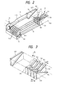
- Fig. 2 is a fragmentary perspective view of the apparatus, particularly showing essential components constituting the apparatus.
- the apparatus includes a winding bobbin feeding unit 20 composed of a winding bobbin conveying unit 1 and a winding bobbin lifting unit 4.
- the winding bobbin conveying unit 1 is constructed in the form of a bucket conveyor having a plurality of buckets 2 arranged at equal intervals in the circumferential direction while extending in the transverse direction with a V-shaped sectional shape.
- Tapes having a predetermined width are fed from a slitter (not shown) where a band-shaped web is subjected to slitting to form a plurality of tapes.
- a row of winding bobbins 3 placed on each bucket 2 is simultaneously seized by the winding bobbin lifting unit 4 from the opposite sides of the latter at a predetermined position on the winding bobbin conveying unit 1 and raised to reach a distributing section 5. Otherwise, the winding bobbins 3 can be raised to reach the distributing section 5 after they are simultaneously seized by a transversely extending common shaft inserted through the center of each of the winding bobbins 3, which are brought into close contact with each other.
- the feeding of the winding bobbins 3 to the distributing section 5 is achieved while the winding bobbins 3 are held in a side-by-side state on inclined surfaces 5a extending in the longitudinal direction from the distributing section 5 and exhibiting a V-shaped contour as seen from the opposite sides. Subsequently, the winding bobbins 3 are distributively fed to an arranging section 9 (described below) while rolling on the inclined surfaces 5a after they are released from the side-by-side state (i.e., the seized state or the close contact state).
- the distributing section 5 includes a plurality of inclined surfaces 5a for holding the winding bobbins 3 thereon and a plurality of triangular cross blocks 6, each having the same thickness as one of the winding bobbins 3.
- the cross blocks 6 are transversely arranged such that a row of cross blocks 6c, each having an inclined surface 5a slantwise extending in one direction, and a row of cross blocks 6d, each having an inclined surface slantwise extending in the opposite direction, are in close contact with each other with the inclined surface 5a interposed therebetween.
- the cross block 6 includes rectangular end blocks 6A and 6B on the opposite sides of the distributing section 5.
- the distributing section 5 is mounted on righthand end parts 8a of slightly inclined floor plates 8, each constituting an upper arranging section 7.
- Another arranging section 9 is mounted on lefthand end parts 8b of the floor plates 8.
- the arranging section 9 is composed of a plurality of guide plates 9a transversely arranged at equally spaced intervals with a pitch dimensionally coincident with the width of each tape as measured between adjacent guide plates 9a and an arranging box 10 located below the guide plates 9a.
- each side wall portion 11 serving as a guide member for widening the pitch between adjacent winding bobbins 3a as they are rolling along the inclined surfaces 5a on the cross block 6c side are arranged between the guide plates 9a and the end blocks 6A and 6B.
- each side wall portion 11 is composed of an upper guide rod 11 a and a lower guide rod 11 b, both of which extend between the guide plates 9a and the end blocks 6A and 6B.
- winding bobbins 3b roll along the inclined surfaces 5b of the cross blocks 6d in the opposite direction relative to the upper arranging section 7, they are received in a trough-shaped bucket 13 of a winding bobbin lowering unit 12 located below the lower ends of the inclined surfaces 5a. Subsequently, the bucket 13 is lowered to the start end side of a lower arranging section 14 by activating a driving system (not shown) for the winding bobbin lowering unit 21.
- the bucket 12 is lowered to the upper ends of inclined surfaces 15 slantwise extending in the opposite direction relative to the inclined surfaces 5b on the cross block 6d side, and thereafter the bucket 13 is turned in the counterclockwise direction (i.e., in the direction of the arrow E in Fig. 1) so that the winding bobbins 3b received in the bucket 13 are caused to roll along the inclined surfaces 15.
- the winding bobbins 3b roll along the inclined surfaces 15 and floor plates 17 under their own weight, guided with the aid of side wall portions 16, they reach a lower arranging box 10 in which they are received in the equally spaced relationship.
- the winding bobbins 3 arranged in the arranging section 9 in the equally spaced relationship are simultaneously taken up by a fitting shaft (not shown) by inserting the fitting shaft through the winding bobbins 3 received in the arranging box 10. Subsequently, the fitting shaft having the winding bobbins 3 mounted thereon is conveyed to and placed on a slitter (not shown) at a predetermined position of the latter to start a slitting operation.
- the winding bobbins 3 are fed to the distributing section 5, they are alternately distributed in opposite directions so that they are exactly arranged in the upper and lower arranging sections 9 with a predetermined distance between adjacent winding bobbins 3.
- a number of winding bobbins 3 can be arranged simultaneously in a very short time compared with the conventional apparatus.
- the time required for executing the arranging step can be shortened to a time period comparable with the time required for executing a slitting step in the slitter, resulting in the productivity of the apparatus being substantially improved.
- the present invention is not be limited to the preceding embodiment.
- the winding bobbin feeding unit 20, the winding bobbin lowering unit 12, the side wall portions 11 and 16 and the arranging section 9 may be designed in a different manner as desired.
- the distributing section 5 may be designed as illustrated in Figs. 3 to 5.
- a plurality of cross blocks 6d, each having a width corresponding to the width W 2 of two winding bobbins 3, and a plurality of cross blocks 6c, each having a width corresponding to a width W 1 of a single winding bobbin 3, are alternately arranged in a side-by-side relationship, as seen in the transverse direction, while the direction of slantwise extension of an inclined surface 5a of each cross block 6d is opposed to the direction of slantwise extension of an inclined surface 5a of each cross block 6c.
- this modified embodiment as shown in Fig.
- winding bobbins 3 are fed to the distributing section 5
- some of the winding bobbins 3 are distributed into a first group of the type composed of two winding bobbins 3b and 3c in close contact with each other, while the remaining winding bobbins 3 are distributed into a second group of the type composed of winding bobbins 3a spaced from each other with a distance L therebetween.
- the winding bobbins 3b and 3c belonging to the first group are fed to the distributing section 5 in a ratio of 2 : 1 in number relative to the winding bobbins 3a belonging to the second group.
- the winding blocks 3b and 3c belonging to the first group are separated from each other with the aid of a cross block (not shown) as shown in Fig. 4(B), whereby all the winding bobbins 3 fed to the distributing section 5 are arranged in conformity with three rows X, Y and Z.
- the distributive arrangement of the winding bobbins in conformity with plural rows in the above- described manner may equally be applied to the case where they are arranged in conformity in four or more of rows.
- a distributing section 25 is constructed as shown in Fig. 5
- an insert shaft 28 is inserted through elongated holes 27 formed through a number of rod-shaped cross bars 26, and the cross bars 26 are then fixedly secured to each other by threadedly tightening a nut 29 so that a cross angle 0 is defined between an inclined surface 5a of one cross bar 26 and that of an adjacent cross bar 26.
- a plurality of winding bobbins are fed to the distributing section including a plurality of inclined surfaces so as to hold the winding bobbins from below while allowing them to be slantwise displaced. Subsequently, while the winding bobbins are arranged in conformity with a specific row as seen in the axial direction, they are released from the retained state in the distributing section so that they are distributively fed to a predetermined location along the inclined surfaces of cross blocks in the specifically predetermined direction.
- the winding bobbins can be fed to predetermined locations within the working time of the slitter, that is, without requiring a longer time than required for the slitting step, as is often the case with the conventional apparatus, resulting in the operational efficiency of the apparatus being substantially improved.
- the apparatus of the present invention does not include any mechanical driving/slidable displacement portion, and moreover, each winding bobbin rolls under its own weight, mechanical wear and associated problems hardly occur on essential components of the apparatus.
- the handling time can substantially be reduced by simultaneously feeding a plurality of winding bobbins to the distributing section, resulting in the productivity of the apparatus being remarkably improved.
Landscapes
- Winding Of Webs (AREA)
- Replacement Of Web Rolls (AREA)
Applications Claiming Priority (2)
| Application Number | Priority Date | Filing Date | Title |
|---|---|---|---|
| JP4304390A JP2835668B2 (ja) | 1992-10-19 | 1992-10-19 | 巻芯振分け装置及び方法 |
| JP304390/92 | 1992-10-19 |
Publications (2)
| Publication Number | Publication Date |
|---|---|
| EP0596250A1 true EP0596250A1 (fr) | 1994-05-11 |
| EP0596250B1 EP0596250B1 (fr) | 1997-04-23 |
Family
ID=17932446
Family Applications (1)
| Application Number | Title | Priority Date | Filing Date |
|---|---|---|---|
| EP93115851A Expired - Lifetime EP0596250B1 (fr) | 1992-10-19 | 1993-09-30 | Dispositif et procédé d'alimentation d'une pluralité de bobinot d'une manière distribuante |
Country Status (4)
| Country | Link |
|---|---|
| US (1) | US5407056A (fr) |
| EP (1) | EP0596250B1 (fr) |
| JP (1) | JP2835668B2 (fr) |
| DE (1) | DE69310090T2 (fr) |
Cited By (3)
| Publication number | Priority date | Publication date | Assignee | Title |
|---|---|---|---|---|
| EP0705783A1 (fr) * | 1994-09-21 | 1996-04-10 | Valmet Corporation | Méthode et dispositif pour arrêter un ensemble de rouleaux |
| DE10155133A1 (de) * | 2001-11-12 | 2003-05-22 | Kampf Gmbh & Co Maschf | Vorrichtung zum Positionieren von entlang einer Führung verschiebbaren Elementen |
| CN110902444A (zh) * | 2019-12-18 | 2020-03-24 | 嘉兴市博莱特纸业股份有限公司 | 箱纸板用大宽幅高速下引纸复卷机 |
Citations (7)
| Publication number | Priority date | Publication date | Assignee | Title |
|---|---|---|---|---|
| DE233798C (fr) * | ||||
| US2494939A (en) * | 1948-01-13 | 1950-01-17 | L G S Spring Clutch Corp | Separation of cylinders from spheres |
| US2840320A (en) * | 1956-05-10 | 1958-06-24 | Csutor Frank | Tape winding bar loader and unloader |
| WO1987006919A1 (fr) * | 1986-05-09 | 1987-11-19 | Meccanica Comasca S.R.L. | Machine a refendre et a enrouler des rubans |
| EP0315568A2 (fr) * | 1987-11-05 | 1989-05-10 | Beloit Corporation | Machine de coupe de rouleaux |
| EP0324709A2 (fr) * | 1988-01-13 | 1989-07-19 | Beloit Corporation | Dispositif de coupe de bande |
| EP0360948A1 (fr) * | 1988-09-28 | 1990-04-04 | GHEZZI & ANNONI S.P.A. | Machine comportant un cycle opératoire continu pour l'emballage sous forme de bobines de divers matériaux en bande à l'aide de plusieurs coupes longitudinales simultanées effectuées dans une large bande de matériau provenant d'un rouleau |
Family Cites Families (11)
| Publication number | Priority date | Publication date | Assignee | Title |
|---|---|---|---|---|
| US2500699A (en) * | 1949-03-18 | 1950-03-14 | Hawaiian Pineapple Co Ltd | Case packer |
| US2947401A (en) * | 1957-06-10 | 1960-08-02 | Leading Engineering And Mfg Co | Flexible chute |
| US3008591A (en) * | 1959-10-16 | 1961-11-14 | Joseph C Cantelmo | Remotely loaded stocking apparatus for grocery and like products |
| US3191752A (en) * | 1963-03-28 | 1965-06-29 | Harold B Biehn | Bulk material distributor |
| US3554356A (en) * | 1968-04-22 | 1971-01-12 | Kaiser Ind Corp | Dispensing chute device |
| GB1313856A (en) * | 1969-07-05 | 1973-04-18 | Masson Scott Thrissell Eng Ltd | Multiple reel unwind stands |
| DE2942163A1 (de) * | 1979-10-18 | 1981-04-30 | Carl Schenck Ag, 6100 Darmstadt | Verfahren und vorrichtung zum aufteilen eines foerderstromes |
| US4392567A (en) * | 1980-11-12 | 1983-07-12 | Glebov Vladimir P | Feeder of bulk materials |
| JPS6194977A (ja) * | 1984-10-16 | 1986-05-13 | Murata Mach Ltd | パツケ−ジ格納装置 |
| IT1191533B (it) * | 1986-03-04 | 1988-03-23 | Matics Srl | Dispositivo trasportatore di bobine |
| IT1224211B (it) * | 1987-05-06 | 1990-09-26 | Loepfe Ag Geb | Sistema di confezione rocche a metratura differenziata |
-
1992
- 1992-10-19 JP JP4304390A patent/JP2835668B2/ja not_active Expired - Fee Related
-
1993
- 1993-09-30 DE DE69310090T patent/DE69310090T2/de not_active Expired - Fee Related
- 1993-09-30 EP EP93115851A patent/EP0596250B1/fr not_active Expired - Lifetime
- 1993-10-06 US US08/132,325 patent/US5407056A/en not_active Expired - Lifetime
Patent Citations (7)
| Publication number | Priority date | Publication date | Assignee | Title |
|---|---|---|---|---|
| DE233798C (fr) * | ||||
| US2494939A (en) * | 1948-01-13 | 1950-01-17 | L G S Spring Clutch Corp | Separation of cylinders from spheres |
| US2840320A (en) * | 1956-05-10 | 1958-06-24 | Csutor Frank | Tape winding bar loader and unloader |
| WO1987006919A1 (fr) * | 1986-05-09 | 1987-11-19 | Meccanica Comasca S.R.L. | Machine a refendre et a enrouler des rubans |
| EP0315568A2 (fr) * | 1987-11-05 | 1989-05-10 | Beloit Corporation | Machine de coupe de rouleaux |
| EP0324709A2 (fr) * | 1988-01-13 | 1989-07-19 | Beloit Corporation | Dispositif de coupe de bande |
| EP0360948A1 (fr) * | 1988-09-28 | 1990-04-04 | GHEZZI & ANNONI S.P.A. | Machine comportant un cycle opératoire continu pour l'emballage sous forme de bobines de divers matériaux en bande à l'aide de plusieurs coupes longitudinales simultanées effectuées dans une large bande de matériau provenant d'un rouleau |
Cited By (4)
| Publication number | Priority date | Publication date | Assignee | Title |
|---|---|---|---|---|
| EP0705783A1 (fr) * | 1994-09-21 | 1996-04-10 | Valmet Corporation | Méthode et dispositif pour arrêter un ensemble de rouleaux |
| DE10155133A1 (de) * | 2001-11-12 | 2003-05-22 | Kampf Gmbh & Co Maschf | Vorrichtung zum Positionieren von entlang einer Führung verschiebbaren Elementen |
| CN110902444A (zh) * | 2019-12-18 | 2020-03-24 | 嘉兴市博莱特纸业股份有限公司 | 箱纸板用大宽幅高速下引纸复卷机 |
| CN110902444B (zh) * | 2019-12-18 | 2021-04-13 | 嘉兴市博莱特纸业股份有限公司 | 箱纸板用大宽幅高速下引纸复卷机 |
Also Published As
| Publication number | Publication date |
|---|---|
| EP0596250B1 (fr) | 1997-04-23 |
| JP2835668B2 (ja) | 1998-12-14 |
| US5407056A (en) | 1995-04-18 |
| DE69310090T2 (de) | 1997-07-31 |
| JPH06127766A (ja) | 1994-05-10 |
| DE69310090D1 (de) | 1997-05-28 |
Similar Documents
| Publication | Publication Date | Title |
|---|---|---|
| US3718062A (en) | Product handling system for cooling beds | |
| DE4244270B4 (de) | Vorrichtung zur Ausbildung von Stapeln aus banderolierten Blattbündeln | |
| US4752176A (en) | Depository for accumulations of paper sheets | |
| EP1209107B1 (fr) | Méthode et dispositif pour le changement de cadres d'enroulement à une chaíne de dispositifs de bobinage | |
| DE60103912T2 (de) | Verfahren und vorrichtung zum sortieren von rollen | |
| DE3824874A1 (de) | Auflaufspulentransportvorrichtung | |
| IT8648031A1 (it) | Apparecchiatura per alimentare bobine di filatura | |
| DE19938151C2 (de) | Zubringereinrichtung (Servicer) für eine Reifenaufbautrommel | |
| US5407056A (en) | Apparatus and method for distributively feeding plural winding bobbins | |
| DE2509859A1 (de) | Vorrichtung zur ablage und entnahme von profilelementen | |
| US6435352B1 (en) | Sorting machine for stacks of sheet metal panels | |
| EP0325411A1 (fr) | Installation et procédé de conditionnement de tubes | |
| EP0243753B1 (fr) | Procédé et dispositif pour traiter des produits imprimés, comme journaux, magazines et analogues, arrivant en formation imbriquée | |
| DE3902978A1 (de) | Spulentransportvorrichtung | |
| EP2214989B1 (fr) | Dispositif de stockage | |
| EP2669223B1 (fr) | Procédé et dispositif pour l'enroulement de bandes de fibres, notamment de bandes partielles de papier et de carton, notamment de bandes partielles de papier et de carton | |
| IT202000003880A1 (it) | Metodo per la composizione di nuclei lamellari, sistema di presa per pacchi lamellari ed impianto di produzione nuclei lamellari | |
| US6311829B1 (en) | Device to separate rolled bars | |
| DE3942492A1 (de) | Palettiervorrichtung fuer spulen | |
| DD254725A5 (de) | Verfahren und vorrichtung von in schuppenformation anfallenden druckereierzeugnissen | |
| EP1581450B1 (fr) | Procede pour convoyeur et convoyeur | |
| EP0390484B1 (fr) | Appareil de transfert horizontal rotatif | |
| DE69904375T2 (de) | Verfahren und Vorrichtung zum Transportieren von Matten aus Steinwolle oder anderem thermisch isolierenden Material | |
| DE3200632C2 (fr) | ||
| EP0441990B1 (fr) | Procédé pour le stockage provisoire chaotique des bobines et dispositif d'emmagasinage et de sortie pour ceux-ci |
Legal Events
| Date | Code | Title | Description |
|---|---|---|---|
| PUAI | Public reference made under article 153(3) epc to a published international application that has entered the european phase |
Free format text: ORIGINAL CODE: 0009012 |
|
| AK | Designated contracting states |
Kind code of ref document: A1 Designated state(s): DE FR |
|
| 17P | Request for examination filed |
Effective date: 19940902 |
|
| 17Q | First examination report despatched |
Effective date: 19960110 |
|
| GRAG | Despatch of communication of intention to grant |
Free format text: ORIGINAL CODE: EPIDOS AGRA |
|
| GRAH | Despatch of communication of intention to grant a patent |
Free format text: ORIGINAL CODE: EPIDOS IGRA |
|
| GRAH | Despatch of communication of intention to grant a patent |
Free format text: ORIGINAL CODE: EPIDOS IGRA |
|
| GRAA | (expected) grant |
Free format text: ORIGINAL CODE: 0009210 |
|
| AK | Designated contracting states |
Kind code of ref document: B1 Designated state(s): DE FR |
|
| REF | Corresponds to: |
Ref document number: 69310090 Country of ref document: DE Date of ref document: 19970528 |
|
| ET | Fr: translation filed | ||
| PLBE | No opposition filed within time limit |
Free format text: ORIGINAL CODE: 0009261 |
|
| STAA | Information on the status of an ep patent application or granted ep patent |
Free format text: STATUS: NO OPPOSITION FILED WITHIN TIME LIMIT |
|
| 26N | No opposition filed | ||
| PGFP | Annual fee paid to national office [announced via postgrant information from national office to epo] |
Ref country code: DE Payment date: 20070927 Year of fee payment: 15 |
|
| REG | Reference to a national code |
Ref country code: FR Ref legal event code: TP Ref country code: FR Ref legal event code: CD |
|
| PGFP | Annual fee paid to national office [announced via postgrant information from national office to epo] |
Ref country code: FR Payment date: 20070914 Year of fee payment: 15 |
|
| REG | Reference to a national code |
Ref country code: FR Ref legal event code: ST Effective date: 20090529 |
|
| PG25 | Lapsed in a contracting state [announced via postgrant information from national office to epo] |
Ref country code: DE Free format text: LAPSE BECAUSE OF NON-PAYMENT OF DUE FEES Effective date: 20090401 |
|
| PG25 | Lapsed in a contracting state [announced via postgrant information from national office to epo] |
Ref country code: FR Free format text: LAPSE BECAUSE OF NON-PAYMENT OF DUE FEES Effective date: 20080930 |