EP0596349B1 - Support pour installation électrique - Google Patents
Support pour installation électrique Download PDFInfo
- Publication number
- EP0596349B1 EP0596349B1 EP93117203A EP93117203A EP0596349B1 EP 0596349 B1 EP0596349 B1 EP 0596349B1 EP 93117203 A EP93117203 A EP 93117203A EP 93117203 A EP93117203 A EP 93117203A EP 0596349 B1 EP0596349 B1 EP 0596349B1
- Authority
- EP
- European Patent Office
- Prior art keywords
- subassemblies
- side walls
- holes
- carrier
- cover
- Prior art date
- Legal status (The legal status is an assumption and is not a legal conclusion. Google has not performed a legal analysis and makes no representation as to the accuracy of the status listed.)
- Expired - Lifetime
Links
- 238000005452 bending Methods 0.000 claims description 4
- 230000000712 assembly Effects 0.000 abstract description 9
- 238000000429 assembly Methods 0.000 abstract description 9
- 238000001816 cooling Methods 0.000 description 6
- 239000000463 material Substances 0.000 description 4
- 238000005520 cutting process Methods 0.000 description 3
- 230000005672 electromagnetic field Effects 0.000 description 3
- 229910052751 metal Inorganic materials 0.000 description 3
- 239000002184 metal Substances 0.000 description 3
- 238000010079 rubber tapping Methods 0.000 description 3
- 229910052782 aluminium Inorganic materials 0.000 description 2
- XAGFODPZIPBFFR-UHFFFAOYSA-N aluminium Chemical compound [Al] XAGFODPZIPBFFR-UHFFFAOYSA-N 0.000 description 2
- 238000004519 manufacturing process Methods 0.000 description 2
- 238000000034 method Methods 0.000 description 2
- 238000005457 optimization Methods 0.000 description 2
- 230000036316 preload Effects 0.000 description 2
- 230000000284 resting effect Effects 0.000 description 2
- 230000006978 adaptation Effects 0.000 description 1
- 238000004026 adhesive bonding Methods 0.000 description 1
- 238000010276 construction Methods 0.000 description 1
- 238000009749 continuous casting Methods 0.000 description 1
- 230000000694 effects Effects 0.000 description 1
- 238000003780 insertion Methods 0.000 description 1
- 230000037431 insertion Effects 0.000 description 1
- 230000002452 interceptive effect Effects 0.000 description 1
- 230000005855 radiation Effects 0.000 description 1
- 230000003014 reinforcing effect Effects 0.000 description 1
Images


Classifications
-
- H—ELECTRICITY
- H05—ELECTRIC TECHNIQUES NOT OTHERWISE PROVIDED FOR
- H05K—PRINTED CIRCUITS; CASINGS OR CONSTRUCTIONAL DETAILS OF ELECTRIC APPARATUS; MANUFACTURE OF ASSEMBLAGES OF ELECTRICAL COMPONENTS
- H05K7/00—Constructional details common to different types of electric apparatus
- H05K7/14—Mounting supporting structure in casing or on frame or rack
- H05K7/1422—Printed circuit boards receptacles, e.g. stacked structures, electronic circuit modules or box like frames
- H05K7/1424—Card cages
- H05K7/1425—Card cages of standardised dimensions, e.g. 19"-subrack
Definitions
- the invention relates to a subrack for electrical assemblies with two side walls, between which at least four profile rails are arranged, the end faces of which are fastened to the side walls near the corners thereof, guide rails being connected to the profile rails and into which the electrical modules can be inserted .
- the grooves extend in the direction of the width of the profile rails and contain slide nuts or threaded strips which are inserted into the transverse recesses. These cross-shaped grooves occupy a certain length of the profile rails. Another length section is provided for the attachment of the guide holders, which often have guide elements for precise positioning and locking elements for attaching the guide holders to the profile rails.
- the profile rails have threaded holes on the end faces, for which sections with larger wall thicknesses are required.
- the profile rails have a certain extent in the depth direction of the respective subrack.
- the profile rails especially if they have a certain extent, hinder the supply of cooling air to those electrical or electronic components which are arranged on assemblies above the profile rails.
- the invention is based on the problem of optimizing the assembly of various subracks or subracks of elements which build up the subrack.
- the optimization is carried out in particular under the aspects of advantageous cooling air routing, space and material savings, easier assembly, electrical shielding and the associated cost savings or improved operating conditions.
- a particular aspect of the invention lies in the fact that the optional combination of the preferred embodiments according to the invention allows several aspects to be combined simultaneously and in a mutually reinforcing manner.
- One aspect of the present invention is based on the problem of developing profile rails as short as possible in the depth direction of the subrack for a subrack of the type described above, to which cover plates can be attached. This is in particular to save material for the components, but also to enable the cooling air to be advantageously guided in the edge regions according to the invention.
- These profile rails can preferably have grooves with cross-shaped cross sections extending from the end faces.
- a section of the respective profile rail which has a longitudinal hole for screw fastenings of the side walls, opening into said hole, with the center lines perpendicular to the center line of this hole, holes are provided, which have a support surface the profile rail for a cover plate are accessible from for fastening the cover plate, as disclosed in claim 1.
- a section of the rail is double, namely used for the fasteners of side walls and cover plates, without additional space being used in the depth direction of the rack.
- the profile rails can therefore be shorter, which increases the space available for the passage of cooling air. This also saves material because the cross-section of the profile rails becomes smaller. The weight of the subrack is also reduced.
- the holes close to the bearing surface merge into a recess which is adapted to heads of screws with plate-shaped edges, the edges being larger in diameter than passages for screws in the cover plate.
- the cover plates are held by the edges of the screws inserted into the holes, while the thicker head centers sit in the recess.
- the fastening means for the cover plates therefore only slightly protrude beyond the cover plates, ie the space required by the subracks in height is not increased by the simple, inexpensive way of fastening the cover plates.
- the cover plates are provided with holes for the air passage, which are evenly distributed in a grid of standardized dimensions on the respective cover plate, the holes in the rails being arranged in a row in the same grid or a multiple of this grid as that holes in the cover plates arranged in a row.
- the cover plates from existing perforated panels can be quickly and easily cut to the size required for a particular subrack.
- the profiled rails each contain a longitudinally extending groove, which is arranged at a distance from the row of holes and extends from a broad side of the profiled rail arranged on the outside of the module, into which angled ends of the cover plates protrude and are electrically conductively connected to at least one wall of the groove by means of contact springs are.
- the contact springs are U-shaped and one leg of the contact springs contains at least one resiliently projecting finger.
- the finger or fingers are made in particular from the inn by cutting a strip.
- the resiliently projecting fingers allow the contact springs to be plugged onto the angled ends of the cover plates before the cover plates and profile rails are joined together.
- the contact springs adhere to the edges and can be pressed into the profile rail grooves together with the cover plates during assembly.
- the two legs of the respective contact spring each lie on a groove wall and on the inner side of the angled end.
- angled ends are difficult to insert by hand, since one leg of the spring has to be detached from the groove wall.
- cover plate arranged at the top or bottom of the subrack has angled ends that run parallel to the side walls of the subrack and face the inside of the side wall, and that each has an S-shaped cross section having contact spring engages around the longitudinal edges of a side wall and an angled end.
- S-shaped springs can be quickly assembled by hand. Due to the spring action, the contact springs already adhere to the edge of a component, i. H. the contact springs can first be pushed over the edge of the respective side wall or the cover plate; and then the contact spring is pressed over the opposite edge when mounting the cover plate on the subrack.
- cover plates to the respective subrack size is limited to cutting out a block matched to the size of the subrack and bending the edges. Since the cover plates can be produced from perforated plates in a relatively simple manner, there are significant savings in production and assembly.
- the female connectors arranged on the rear of the subrack often have posts protruding to the rear, to which lines can be attached using connection techniques known per se.
- the female connectors are often connected to a backplane circuit board into which the posts are pressed or soldered.
- the backplane and the cables create the desired connections between the posts of the female connectors, which are assigned to the individual modules. In many cases, the back of a rack must be shielded to avoid interference radiation.
- a rear cover hood on the subrack has walls adapted to the rearward extent of the subrack cover space and provided with angled upper and lower edge zones, the edge region of which is in each case contacted with one of the rear profile rails by conductive springs inserted in profile rail grooves, the ends being in contact with one another of the subrack covering side walls are conductively connected to the edge zones via springs, and wherein a rear base plate of the cover has angled edge zones which face the inside of the side walls with the interposition of electrically conductive springs.
- the two side walls near each of their rear ends have a fastening bracket directed towards the interior of the cover space, which has a section set back against the bent edge of the rear wall of the cover and to which the rear wall is screwed.
- the cover can be installed quickly and easily.
- the conductive springs are expediently glued to the angled edges.
- the device for electromagnetic shielding described above can be used for different subracks and therefore represents a further preferred embodiment of the inventive idea.
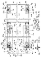
- a rack 1 contains two side walls 2, of which the longitudinal section shows only one, and four rails 3, 4, 5, 6, which are used in a shorter rack, and two further rails 6a, 7, which are in a rack with greater depth are also provided.
- the profile rails 3, 4, 5, 6 are each fastened to the side walls 2 close to the corners thereof.
- the profile rails 6a, 7 are fastened close to the rear corners of the side walls, while the profile rails 5, 6 are arranged at a distance from the rear profile rails at the end of the space allocated to the modules.
- the rails 3 to 6, 6a and 7 are made of aluminum and are, for. B. manufactured in a continuous casting process.
- Guide brackets 8, 9 are fastened to the profile rails 3 to 6 in parallel to one another.
- 1 shows an upper guide holder 8, which is fastened to the profile rails 3 and 5, and a lower guide holder 9, which is fastened to the profile rails 4, 6.
- Modules in the form of flat plug-in modules are used in a pair of opposing guide holders 8, 9.
- Such assemblies are known and are not shown in detail.
- the assemblies usually contain a printed circuit board that is equipped with electrical or electronic components.
- the profile rails 3 to 6 are flat.
- the profile rails 3, 4 arranged on the front of the rack are designed somewhat differently than the profile rails 5, 6, 6a and 7 at the rear end of the rack 1.
- the profile rails 3, 4 each contain a groove 10 of cruciform shape which extends over the entire length of the profile rail Cross-section, which is open after the flat front end of the profile rail 3, 4 and receives slide nuts or threaded strips in its transverse bulges, are inserted into the screws with which the front strips (not shown) of plug-in modules are fastened to the subrack. This fixes the plug-in modules in the subrack.
- the grooves 10 take up a certain distance in the depth direction of the profile rails 3, 4. Other fastening means for the plug-in modules can also be provided on the profile rails.
- a hole 11 runs in the rails 3, 4, which extends over the entire length of the rails. These holes are intended for receiving self-tapping screws 12, with which the side walls 2 are screwed onto the end faces of the profile rails 3, 4.
- a series of holes 14 spaced apart in a grid dimension are provided on the groove bottom of the grooves 13.
- the holes 14 are intended for receiving screws 15 with which the guide holders 8, 9 are screwed onto the profile rails 3, 4. Laterally next to and at a distance from the grooves 13, there is a further hole 16 in the rails 3, 4, which extends over the entire length of the rails.
- the holes 16 are intended for receiving additional self-tapping screws 17 with which the side walls 2 are additionally screwed to the profile rails 3, 4.
- the attachment of the side walls 2 each on the rails 3, 4 with two screws 12, 17 improves the stability.
- the front screws 12 are also used to fasten side brackets 17 a to the rack 1. These side angles are used as a stop when inserting the rack 1 into a rack or cabinet.
- the side brackets 17a can be released from the rack 1 by unscrewing the screws 12 without this affecting the fixed connection of the other rack parts.
- the side bracket 17a on the rear rails 5, 6 or 6a, 7 can be attached to the rack 1 on its back with a supporting part, for. B. a wall to connect.
- a further groove 18 runs in each profile rail 3, 4, which is open on the side of the profile rail facing away from the guide holders 8, 9 and has a rectangular cross section.
- the groove 18 is arranged at a distance from the hole 16 and has the same center plane 19 as the hole 16.
- the central plane 19 extends at a right angle to the central longitudinal axis 20 of the subrack 1.
- the central plane 19 is to be understood as a plane which runs through the center of the groove 18 parallel to the side walls and through the center line 21 of the hole 16.
- the holes 22 have central axes which lie in the plane 19 and run at a right angle to the central axis 21 of the hole 16.
- the holes 22 and 16 therefore occupy the same space in the rails 3, 4. In this way, the profile rails 3, 4 are shortened.
- the holes 22 are intended for fasteners that are used to connect cover plates 23 to the profile rails 3, 4.
- the cover plates 23, which are attached to the top and bottom of the rack 1, serve on the one hand to protect the interior of the rack and on the other hand have recesses for the passage of cooling air.
- the recesses are arranged in the cover plate shown in Fig. 2b, which is suitable for the upper and lower cover of the rack 1, in the form of holes 24 of equal size, of which only a few are shown in Fig. 2b.
- the holes 24 are arranged in parallel rows and columns.
- the holes 24 arranged in a row are each arranged along the same center line 25.
- the holes 24 arranged in a column also extend along the same center line 26 at equal distances from one another.
- the holes 24 run along the parallel diagonals 27, which are inclined against the edges of the cover plates 23.
- the cover plates 23 therefore have a regular hole pattern.
- the holes 24 are matched to a metric standard system and have z. B. 6.5 mm in diameter.
- the centers of the adjacent holes 24 are also at a distance from the standard system, for. B. 12.5 mm apart.
- the center distances of the holes 22 are matched to the center distances of the holes 24 of the cover plates 23, i. H.
- Adjacent holes 24 or every third or fourth hole 24 comes to lie over a corresponding hole 22 when a cover plate 24 is placed on the profile rails 3, 5 or 4, 6 and the holes 22, 24 are aligned with one another. Therefore, the holes 24 are also used for fastening the cover plate 23 to the profile rails 3, 5 and 4, 6.
- Screws 28, one of which is shown in cross section in FIG. 2a, are used as fastening means for the cover plates 23.
- the screw 28 has a plate-shaped flat edge 29.
- the plate-shaped edge 29 can be inseparably connected to the screw 28, which has a slotted head. This has advantages for simplifying assembly. But it is also possible to use the plate-shaped edge 29 as a washer.
- the outer diameter of the edge 29 is larger than the diameter of the holes 24.
- the shaft of the screw 28 is smaller than the diameter of the holes 24.
- the diameter of the holes 22 is smaller than the diameter of the holes 24 and adapted to the shaft of the screws 28.
- a plurality of screws 28, which are preferably designed as self-tapping screws, are screwed into holes 22 when cover plates 23 are resting on the profiled rails 3, 5 or 4, 6.
- FIG. 1 the rack 1 is shown with a cover plate 23 on the top and bottom.
- the lower cover plate 23 is fastened in the same way as the upper cover plate, without screws being shown in FIG. 1.
- the cover plates 23 have angled ends, of which the front end 30 and the rear end 31 are shown in FIG. 1.
- the front angled end 30 projects into the groove 13.
- the rear end 31 projects into a groove 32 of the rearmost profile rail 6a.
- the grooves 13 receive the heads of the screws 28, which are thicker than the diameter of the holes 22.
- the screws 22 screwed into the holes 22 lie, as shown in FIG. 1, with their edges 29 on the areas of the cover plate 23 next to them Holes 24 on.
- the edges 29 protrude only slightly from the cover plate 23 resting on the profile rails 3, 5, 6, so that there is practically no additional space requirement in terms of height. A sufficient firm connection is with edge thicknesses of z. B. reached 0.3 mm.
- a U-shaped contact spring 33 is inserted into the groove 13, which is shown in perspective in FIG. 2c.
- the contact spring 33 contains two legs 34, 35, each of which bears against a wall of the groove 13 and against the inside of the angled end 30 under spring preload and thus establish a good electrical connection between the cover plate 23 and the profile rail 3.
- a similarly conductive connection is provided in the groove 32 by means of a contact spring 33.
- the contact spring 33 contains at least two fingers 36 projecting outward from the leg 35.
- the fingers 36 are produced by removing the lateral connection of leg sections or strips to the rest of the leg 35 and by pre-bending the sections or strips.
- the contact springs 33 are first pushed over the bent ends 30 in such a way that the edges protrude into the gap between the leg 35 and the fingers 36.
- the contact spring 33 holds at the ends due to the spring action between leg 35 and finger 36.
- the end 30 with the attached contact spring 33 is inserted into the groove 13 or 32, the legs 34, 35 laying against the corresponding walls of the groove 13 or 32 and the angled end 30.
- the cover plates 23 each have 90 ° angled lateral ends 37, 38.
- the distance between the outer sides of the two ends 37, 38 is smaller than the distance between the inner surfaces of the side walls 2.
- the ends 37, 38 each face the inner sides of the walls 2 with their outer surfaces. This can be seen in FIG. 3.
- Conductive contact springs 39 with an S-shaped cross section provide a low-resistance connection between the metallic side walls 2, which are made of sheet metal, for. B. anodized aluminum sheet, and the cover plates 23 ago, which can be made of the same material.
- the S-shaped contact springs 39 wrap one half around the upper and lower edges of the side walls under spring preload. With the other half, the contact springs 39 wrap around the edges of the angled ends 37, 38.
- the contact springs 39 can be attached by hand to the edges of the side walls 2 or the ends 37, 38, whereupon they remain adhered under spring tension. During assembly, the free edges of the counterparts can be quickly and easily pushed into the corresponding halves of the contact springs 39. The assembly times for the rack 1 can be shortened in this way.
- Fig. 3 can by itself, i. H. 1, 2a and 2c can be used in the case of subracks without the type of fastening of the front or rear ends of the cover plates 23 shown in FIGS.
- FIG. 4 and 5 show the rear part of a rack 40, which is protected against disturbing electromagnetic fields on its back differently than the rack according to.
- Fig. 1. According to the subrack. Fig. 1 is attached to the rear rails 6a, 7, a hood 41 which is adjacent to the rear end faces of the rails 6a, 7 and with these by means not shown, for. B. screws is connected.
- the profile rails 6a, 7 have larger grooves 44 close to their rear ends, which are open towards the top or bottom of the module.
- the edges 42, 43 largely cover the grooves 44.
- V-shaped springs 45 are held in the grooves 44 in transverse recesses, which are not described in more detail.
- hood 45a which is then designed in the same way as the hood 41.
- the profile rails 5, 6 and 6a, 7 are also identical in construction or in shape.
- the cover used for the shielding of the profile rails 5 and 6 in FIG. 1 is not shown and described in detail.
- the side walls and cover plates are correspondingly shorter.
- the lower cover plate 23 is fastened to the mounting rails 1 on the mounting rails 4, 6 and 7 in the same way as the flat cover plate. Further details of the attachment are shown in FIG. 1 in connection with the profile rail 3.
- the cover plates 23 are connected to the profile rails 4, 5, 6, 6a and 7 in the same way as the cover plate to the profile rail 3, which is why the connections at the corresponding points are not shown and described in detail.
- a rear cover 46 has a flat bottom plate 47 and an upper side wall 48 and a lower side wall 49.
- the side walls 48, 49 are matched to the space required behind the rails 5, 6, in which the rear posts of the female connectors and other components, for. B. transfer connector can be.
- the two side walls 2 extend to the base plate 47.
- the side walls 48, 49 are angled at right angles from the base plate 47.
- the side walls 48, 49 each have edge zones 50, 51 which are angled at right angles to the inside of the subrack, only one of which is shown in FIG. 4.
- the base plate 47 has edge zones 52 angled at right angles, of which only one is shown in FIG. 4.
- the edge zones 50, 51, 52 are set back relative to the side walls 2 to the interior of the subrack so that a gap designated 53 in FIGS. 4 and 5 is present.
- Arched springs 54 are fastened on the outer sides of the edge zones 50, 51, 52. The attachment can be done by gluing. The springs 54 bear against the side walls 2 when the cover 46 is fastened to the subrack 40 and effect a highly conductive electrical connection for shielding against disturbing electromagnetic fields.
- Mounting brackets 55 are attached to the side walls 2 and extend over only a small part of the heights of the side walls 2.
- the mounting bracket 55 are z. B. soldered, welded or screwed and have bent ends at right angles in the plane of the base plate 47, to which the base plate 47 is screwed by means of screws 56 and nuts 57.
- the type of protection of the rear parts of a rack shown in FIGS. 4 and 5 can also be used independently of the type of shielding by cover plate 23 described above and allows simple means to effectively dampen interfering electromagnetic fields, be it that they are inside the Subrack arise, or it is that they act on the subrack from the outside.
Landscapes
- Microelectronics & Electronic Packaging (AREA)
- Engineering & Computer Science (AREA)
- Shielding Devices Or Components To Electric Or Magnetic Fields (AREA)
- Conveying And Assembling Of Building Elements In Situ (AREA)
- Casings For Electric Apparatus (AREA)
- Forklifts And Lifting Vehicles (AREA)
- Mounting Of Printed Circuit Boards And The Like (AREA)
- Coupling Device And Connection With Printed Circuit (AREA)
- Thermistors And Varistors (AREA)
- Dry Shavers And Clippers (AREA)
- Input Circuits Of Receivers And Coupling Of Receivers And Audio Equipment (AREA)
- Developing Agents For Electrophotography (AREA)
- Fixed Capacitors And Capacitor Manufacturing Machines (AREA)
- Formation Of Insulating Films (AREA)
Claims (10)
- Châssis de support (1) pour composants électriques comportant deux parois latérales (2) entre lesquelles sont disposés au moins quatre rails profilés (3, 4, 5, 6, 6a, 7) dont les faces frontales sont fixées à proximité des angles des parois latérales, les rails profilés étant reliés à des supports de guide (8, 9) dans lesquels les composants électriques sont insérables,
caractérisé en ce que
dans une section des rails profilés respectifs (3, 4, 5, 6, 6a, 7), qui présente un trou longitudinal (16) pour des fixations par vis des parois latérales (2), il est prévu des trous (22) qui débouchent dans ledit trou (16), dont les lignes médianes (19) s'étendent à angle droit par rapport à la ligne médiane (21) de ce trou (16) et qui sont accessibles par une face d'application (22a) du rail profilé (3, 4, 5, 6, 6a, 7) pour une tôle de recouvrement (23) en vue de la fixation de la tôle de recouvrement (23). - Châssis de support pour composants selon la revendication 1,
caractérisé en ce que
les trous (22) se transforment, à proximité de la surface d'application (22a), en une cavité qui est adaptée aux têtes de vis (28) comprenant des bords (29) formant collerette et en ce que les diamètres des bords sont plus grands que les passages des vis dans la tôle de recouvrement. - Châssis de support pour composants selon la revendication 1 ou 2,
caractérisé en ce que
les tôles de recouvrement (23) sont munies de trous (24) pour le passage de l'air qui sont répartis, en réseau de norme standard, régulièrement sur la tôle de recouvrement respective et en ce que les trous (22) des rails profilés (3, 4, 5, 6, 6a, 7) sont disposés sur une rangée dans le même réseau ou dans un multiple du réseau, comme le sont les trous (24) des tôles de recouvrement (23) disposés sur une rangée. - Châssis de support pour composants selon l'une ou plusieurs des revendications précédentes,
caractérisé en ce que,
les rails profilés (3, 4, 5, 6, 6a, 7) comprennent respectivement une rainure (13) s'étendant longitudinalement, à distance de la rangée des trous (22) et partant d'une face large des rails profilés disposée sur la face externe côté composants, rainure dans laquelle s'engagent les extrémités coudées (30) des tôles de recouvrement (23), extrémités qui sont reliées, de manière conductrice électriquement par des ressorts de contact (33), à au moins une paroi de la rainure (13). - Châssis de support pour composants selon l'une ou plusieurs des revendications précédentes,
caractérisé en ce que
les ressorts de contact (33) ont une forme en U et en ce qu'au moins une branche de U (35) des ressorts de contact (33) comprend au moins un doigt (36) saillant de manière élastique. - Châssis de support pour composants selon la revendication 5,
caractérisé en ce que
le doigt (36) est réalisé par l'entaille de fentes latérales dans les branches (35) et par précambrage. - Châssis de support pour composants selon l'une ou plusieurs des revendications précédentes,
caractérisé en ce que
la tôle de recouvrement (23), disposée en haut ou en bas sur le châssis de support (1) de composants, présente des extrémités coudées (37, 38) qui s'étendent parallèlement aux parois latérales (2) du châssis de support (1) pour composants et qui sont opposées aux faces internes des parois latérales (2) et en ce qu'un ressort de contact (39), présentant une coupe transversale en S, entoure les bords longitudinaux d'une paroi latérale (2) et d'une extrémité coudée (37, 38). - Châssis de support pour composants selon l'une ou plusieurs des revendications précédentes,
caractérisé en ce qu'
un capot de recouvrement arrière (46) sur le châssis de support (1) de composants présente des parois (48, 49) qui sont adaptées à la cavité arrière de l'espace de recouvrement du châssis de support de composants, qui sont munies de zones de bordures (50, 51) coudées supérieures et inférieures et dont les zones de bordures entrent en contact avec l'un des rails profilés arrière par l'intermédiaire de ressorts (45) conducteurs, insérés dans des rainures (44) des rails profilés, en ce que les parois latérales (2), s'étendant jusqu'à l'extrémité de l'espace de recouvrement du châssis de support de composants, sont reliées de manière conductrice aux zones de bordures (50, 51) par des contacts (54) et en ce qu'une plaque de fond arrière (47) du capot de recouvrement présente des zones de bordures coudées (52) qui sont opposées aux faces internes des parois latérales et entre lesquelles interviennent des ressorts (54) électriquement conducteurs. - Châssis de support pour composants selon la revendication 8,
caractérisé en ce que
les deux parois latérales présentent, à proximité de leurs extrémités arrière, des équerres de fixation (55) qui sont dirigées vers l'intérieur du châssis de support pour composants et sur lesquelles peut être vissée la plaque de fond (47) du capot de recouvrement (46). - Châssis de support de composants selon la revendication 8 ou 9, caractérisé en ce qu'
entre les zones de bordures (50, 51, 52) et les parois latérales, les ressorts (54) sont collés contre les zones de bordure.
Applications Claiming Priority (2)
| Application Number | Priority Date | Filing Date | Title |
|---|---|---|---|
| DE4237447A DE4237447A1 (de) | 1992-11-06 | 1992-11-06 | Baugruppenträger |
| DE4237447 | 1992-11-06 |
Publications (3)
| Publication Number | Publication Date |
|---|---|
| EP0596349A2 EP0596349A2 (fr) | 1994-05-11 |
| EP0596349A3 EP0596349A3 (en) | 1994-06-08 |
| EP0596349B1 true EP0596349B1 (fr) | 1995-12-06 |
Family
ID=6472225
Family Applications (1)
| Application Number | Title | Priority Date | Filing Date |
|---|---|---|---|
| EP93117203A Expired - Lifetime EP0596349B1 (fr) | 1992-11-06 | 1993-10-23 | Support pour installation électrique |
Country Status (6)
| Country | Link |
|---|---|
| EP (1) | EP0596349B1 (fr) |
| AT (1) | ATE131341T1 (fr) |
| DE (2) | DE4237447A1 (fr) |
| DK (1) | DK0596349T3 (fr) |
| ES (1) | ES2080571T3 (fr) |
| IL (1) | IL107503A0 (fr) |
Families Citing this family (7)
| Publication number | Priority date | Publication date | Assignee | Title |
|---|---|---|---|---|
| DE19644418C5 (de) * | 1996-10-25 | 2004-10-28 | Schroff Gmbh | Baugruppenträger |
| DE19644420C1 (de) * | 1996-10-25 | 1997-08-28 | Schroff Gmbh | Baugruppenträger |
| DE19646063C2 (de) * | 1996-11-08 | 2002-04-04 | Aeg Intermas Gmbh | Kabelgehäuse |
| DE29619475U1 (de) * | 1996-11-11 | 1997-12-11 | Siemens AG, 80333 München | Baugruppenträger für Leiterplatten mit Mittelquerschienen |
| DE29619565U1 (de) * | 1996-11-11 | 1997-12-18 | Siemens AG, 80333 München | Baugruppenträger für Leiterplatten mit abgeschirmter Front- und Rückseite |
| DE29817537U1 (de) * | 1998-10-01 | 1999-11-18 | Siemens AG, 80333 München | Kontaktfederleiste zum Aufstecken auf eine Halteleiste, und Kontaktteil mit Kontaktfederleiste und Halteleiste, insbesondere Frontplatte einer Flachbaugruppe |
| DE19916882C1 (de) * | 1999-04-14 | 2001-07-26 | Apw Electronics Gmbh | Als Gehäuse ausgebildeter Baugruppenträger |
Family Cites Families (14)
| Publication number | Priority date | Publication date | Assignee | Title |
|---|---|---|---|---|
| DE3241067A1 (de) * | 1982-11-06 | 1984-05-10 | Licentia Patent-Verwaltungs-Gmbh, 6000 Frankfurt | Baugruppentraeger fuer elektronische baugruppen |
| DE3633284A1 (de) * | 1986-09-30 | 1988-04-07 | Loh Kg Rittal Werk | Mehrzweck-tischgehaeuse |
| DE3716828A1 (de) * | 1987-05-20 | 1988-12-01 | Broadcast Television Syst | Geraet der elektrischen nachrichtentechnik |
| DE8714497U1 (de) * | 1987-10-30 | 1987-12-10 | Siemens AG, 1000 Berlin und 8000 München | Etagenschirmblech für einen Baugruppenträger |
| DE3928461C3 (de) * | 1989-08-29 | 1997-10-16 | Aeg Intermas Gmbh | Baugruppenträger |
| DE4016797C2 (de) * | 1990-05-25 | 1998-04-09 | Daimler Benz Aerospace Ag | Vorrichtung zur hochfrequenzdichten Abschirmung eines Einschub-Gehäuses |
| DE9012163U1 (de) * | 1990-08-24 | 1990-12-13 | Niedax GmbH + Co KG Gesellschaft für Verlegungsmaterial, 5460 Linz | Elektrisches Übertragungskontaktelement für offene, mit Abdeckungen verschliessbare, auf dem Kanalboden eine Montageschiene aufweisende Installationskanäle |
| DE9017420U1 (de) * | 1990-12-24 | 1991-03-14 | Licentia Patent-Verwaltungs-Gmbh, 6000 Frankfurt | Baugruppenträger |
| DE4102019C1 (fr) * | 1991-01-24 | 1992-07-09 | Schroff Gmbh, 7541 Straubenhardt, De | |
| DE4110800C1 (fr) * | 1991-04-04 | 1992-07-23 | Schroff Gmbh, 7541 Straubenhardt, De | |
| ATE118300T1 (de) * | 1991-04-08 | 1995-02-15 | Loh Kg Rittal Werk | Kassette zum einbau in einen baugruppenträger. |
| DE4114484C2 (de) * | 1991-05-03 | 1993-12-02 | Licentia Gmbh | Baugruppenträger |
| JP3011379B2 (ja) * | 1991-07-17 | 2000-02-21 | 北川工業株式会社 | 電磁波シールド用ガスケット |
| DE9209519U1 (de) * | 1992-07-16 | 1992-08-27 | Schroff Gmbh, 7541 Straubenhardt | HF-dichter Baugruppenträger |
-
1992
- 1992-11-06 DE DE4237447A patent/DE4237447A1/de not_active Withdrawn
-
1993
- 1993-10-23 DE DE59301102T patent/DE59301102D1/de not_active Expired - Fee Related
- 1993-10-23 DK DK93117203.5T patent/DK0596349T3/da active
- 1993-10-23 ES ES93117203T patent/ES2080571T3/es not_active Expired - Lifetime
- 1993-10-23 EP EP93117203A patent/EP0596349B1/fr not_active Expired - Lifetime
- 1993-10-23 AT AT93117203T patent/ATE131341T1/de not_active IP Right Cessation
- 1993-11-05 IL IL10750393A patent/IL107503A0/xx unknown
Also Published As
| Publication number | Publication date |
|---|---|
| ATE131341T1 (de) | 1995-12-15 |
| EP0596349A3 (en) | 1994-06-08 |
| DE59301102D1 (de) | 1996-01-18 |
| IL107503A0 (en) | 1994-02-27 |
| ES2080571T3 (es) | 1996-02-01 |
| DK0596349T3 (da) | 1996-01-08 |
| DE4237447A1 (de) | 1994-05-11 |
| EP0596349A2 (fr) | 1994-05-11 |
Similar Documents
| Publication | Publication Date | Title |
|---|---|---|
| EP0939984B1 (fr) | Armoire de distribution | |
| DE69508396T2 (de) | Schieneneinheit | |
| DE4130355C1 (fr) | ||
| DE3705331A1 (de) | Montageeinheit fuer eine gedruckte schaltung | |
| EP1168905A2 (fr) | Baie électronique et assemblage de baies | |
| DE102010049605A1 (de) | Kastengehäuse und Herstellungsverfahren | |
| EP0415246B1 (fr) | Rack électronique | |
| EP0596349B1 (fr) | Support pour installation électrique | |
| DE3634462C2 (fr) | ||
| EP0838989B1 (fr) | Baie électronique blindée | |
| EP1072179B1 (fr) | Support de modules | |
| EP0516986B1 (fr) | Rack électronique | |
| DE2714562A1 (de) | Baugruppentraeger | |
| EP0573441A1 (fr) | Support blinde de composants electriques enfichables. | |
| DE19609887C1 (de) | Gerätechassis für elektronische Geräte | |
| EP0886992B1 (fr) | Chassis pour appareils electroniques | |
| DE4126576A1 (de) | Baugruppentraeger | |
| DE29604597U1 (de) | Elektromagnetisch abgeschirmter Baugruppenträger mit variabler Befestigungsanordnung zwischen Etagenschirmblechen und Seitenwandblechen | |
| DE4141559C2 (de) | Führungshalter für elektronische Baugruppen | |
| DE19523257C1 (de) | Baugruppenträger | |
| EP0589316B1 (fr) | Rack électronique | |
| AT409047B (de) | Vorrichtung zur erdung einer modular aufgebauten gehäuseeinheit | |
| DE9115845U1 (de) | Baugruppenträger | |
| DE10208401C1 (de) | Bauteilesatz für ein HF-dichtes Gehäuse und Multischalter | |
| DE3531733C2 (fr) |
Legal Events
| Date | Code | Title | Description |
|---|---|---|---|
| PUAI | Public reference made under article 153(3) epc to a published international application that has entered the european phase |
Free format text: ORIGINAL CODE: 0009012 |
|
| PUAL | Search report despatched |
Free format text: ORIGINAL CODE: 0009013 |
|
| AK | Designated contracting states |
Kind code of ref document: A2 Designated state(s): AT BE CH DE DK ES FR GB IT LI NL |
|
| AK | Designated contracting states |
Kind code of ref document: A3 Designated state(s): AT BE CH DE DK ES FR GB IT LI NL |
|
| 17P | Request for examination filed |
Effective date: 19940924 |
|
| 17Q | First examination report despatched |
Effective date: 19950302 |
|
| GRAA | (expected) grant |
Free format text: ORIGINAL CODE: 0009210 |
|
| AK | Designated contracting states |
Kind code of ref document: B1 Designated state(s): AT BE CH DE DK ES FR GB IT LI NL |
|
| REF | Corresponds to: |
Ref document number: 131341 Country of ref document: AT Date of ref document: 19951215 Kind code of ref document: T |
|
| REG | Reference to a national code |
Ref country code: DK Ref legal event code: T3 |
|
| REF | Corresponds to: |
Ref document number: 59301102 Country of ref document: DE Date of ref document: 19960118 |
|
| REG | Reference to a national code |
Ref country code: ES Ref legal event code: FG2A Ref document number: 2080571 Country of ref document: ES Kind code of ref document: T3 |
|
| ET | Fr: translation filed | ||
| REG | Reference to a national code |
Ref country code: CH Ref legal event code: NV Representative=s name: KIRKER & CIE SA |
|
| ITF | It: translation for a ep patent filed | ||
| GBT | Gb: translation of ep patent filed (gb section 77(6)(a)/1977) |
Effective date: 19960221 |
|
| PGFP | Annual fee paid to national office [announced via postgrant information from national office to epo] |
Ref country code: AT Payment date: 19961009 Year of fee payment: 4 Ref country code: FR Payment date: 19961009 Year of fee payment: 4 |
|
| PLBE | No opposition filed within time limit |
Free format text: ORIGINAL CODE: 0009261 |
|
| STAA | Information on the status of an ep patent application or granted ep patent |
Free format text: STATUS: NO OPPOSITION FILED WITHIN TIME LIMIT |
|
| PG25 | Lapsed in a contracting state [announced via postgrant information from national office to epo] |
Ref country code: DK Effective date: 19961023 |
|
| PGFP | Annual fee paid to national office [announced via postgrant information from national office to epo] |
Ref country code: ES Payment date: 19961023 Year of fee payment: 4 |
|
| REG | Reference to a national code |
Ref country code: DK Ref legal event code: EBP |
|
| PG25 | Lapsed in a contracting state [announced via postgrant information from national office to epo] |
Ref country code: BE Effective date: 19961031 |
|
| PGFP | Annual fee paid to national office [announced via postgrant information from national office to epo] |
Ref country code: CH Payment date: 19961120 Year of fee payment: 4 |
|
| 26N | No opposition filed | ||
| REG | Reference to a national code |
Ref country code: CH Ref legal event code: PUE Owner name: LICENTIA PATENT-VERWALTUNGS-GMBH TRANSFER- AEG INT |
|
| REG | Reference to a national code |
Ref country code: GB Ref legal event code: 732E |
|
| REG | Reference to a national code |
Ref country code: ES Ref legal event code: PC2A |
|
| BERE | Be: lapsed |
Owner name: LICENTIA PATENT-VERWALTUNGS-G.M.B.H. Effective date: 19961031 |
|
| REG | Reference to a national code |
Ref country code: FR Ref legal event code: TP |
|
| NLS | Nl: assignments of ep-patents |
Owner name: AEG INTERMAS GMBH |
|
| PG25 | Lapsed in a contracting state [announced via postgrant information from national office to epo] |
Ref country code: GB Free format text: LAPSE BECAUSE OF NON-PAYMENT OF DUE FEES Effective date: 19971023 Ref country code: AT Free format text: LAPSE BECAUSE OF NON-PAYMENT OF DUE FEES Effective date: 19971023 |
|
| PG25 | Lapsed in a contracting state [announced via postgrant information from national office to epo] |
Ref country code: ES Free format text: LAPSE BECAUSE OF EXPIRATION OF PROTECTION Effective date: 19971024 |
|
| PG25 | Lapsed in a contracting state [announced via postgrant information from national office to epo] |
Ref country code: LI Free format text: LAPSE BECAUSE OF NON-PAYMENT OF DUE FEES Effective date: 19971031 Ref country code: FR Free format text: THE PATENT HAS BEEN ANNULLED BY A DECISION OF A NATIONAL AUTHORITY Effective date: 19971031 Ref country code: CH Free format text: LAPSE BECAUSE OF NON-PAYMENT OF DUE FEES Effective date: 19971031 |
|
| PG25 | Lapsed in a contracting state [announced via postgrant information from national office to epo] |
Ref country code: NL Free format text: LAPSE BECAUSE OF NON-PAYMENT OF DUE FEES Effective date: 19980501 |
|
| GBPC | Gb: european patent ceased through non-payment of renewal fee |
Effective date: 19971023 |
|
| REG | Reference to a national code |
Ref country code: CH Ref legal event code: PL |
|
| NLV4 | Nl: lapsed or anulled due to non-payment of the annual fee |
Effective date: 19980501 |
|
| REG | Reference to a national code |
Ref country code: FR Ref legal event code: ST |
|
| REG | Reference to a national code |
Ref country code: ES Ref legal event code: FD2A Effective date: 20010201 |
|
| PGFP | Annual fee paid to national office [announced via postgrant information from national office to epo] |
Ref country code: DE Payment date: 20021030 Year of fee payment: 10 |
|
| PG25 | Lapsed in a contracting state [announced via postgrant information from national office to epo] |
Ref country code: DE Free format text: LAPSE BECAUSE OF NON-PAYMENT OF DUE FEES Effective date: 20040501 |
|
| PG25 | Lapsed in a contracting state [announced via postgrant information from national office to epo] |
Ref country code: IT Free format text: LAPSE BECAUSE OF NON-PAYMENT OF DUE FEES;WARNING: LAPSES OF ITALIAN PATENTS WITH EFFECTIVE DATE BEFORE 2007 MAY HAVE OCCURRED AT ANY TIME BEFORE 2007. THE CORRECT EFFECTIVE DATE MAY BE DIFFERENT FROM THE ONE RECORDED. Effective date: 20051023 |