EP0596431A1 - Apparatus for treating yarn with fluid - Google Patents
Apparatus for treating yarn with fluid Download PDFInfo
- Publication number
- EP0596431A1 EP0596431A1 EP93117620A EP93117620A EP0596431A1 EP 0596431 A1 EP0596431 A1 EP 0596431A1 EP 93117620 A EP93117620 A EP 93117620A EP 93117620 A EP93117620 A EP 93117620A EP 0596431 A1 EP0596431 A1 EP 0596431A1
- Authority
- EP
- European Patent Office
- Prior art keywords
- yarn
- fluid conduits
- fluid
- running direction
- components
- Prior art date
- Legal status (The legal status is an assumption and is not a legal conclusion. Google has not performed a legal analysis and makes no representation as to the accuracy of the status listed.)
- Granted
Links
- 239000012530 fluid Substances 0.000 title claims abstract description 371
- 238000006073 displacement reaction Methods 0.000 description 11
- 230000000694 effects Effects 0.000 description 10
- 125000006850 spacer group Chemical group 0.000 description 6
- 239000004677 Nylon Substances 0.000 description 5
- 229920001778 nylon Polymers 0.000 description 5
- 230000001965 increasing effect Effects 0.000 description 4
- 230000009191 jumping Effects 0.000 description 4
- 238000000034 method Methods 0.000 description 4
- 239000003566 sealing material Substances 0.000 description 3
- 230000006866 deterioration Effects 0.000 description 2
- 230000002708 enhancing effect Effects 0.000 description 2
- 238000004519 manufacturing process Methods 0.000 description 2
- 230000004048 modification Effects 0.000 description 2
- 238000012986 modification Methods 0.000 description 2
- 238000005381 potential energy Methods 0.000 description 2
- 230000001154 acute effect Effects 0.000 description 1
- 230000000903 blocking effect Effects 0.000 description 1
- 239000000835 fiber Substances 0.000 description 1
- 239000000463 material Substances 0.000 description 1
- 230000000452 restraining effect Effects 0.000 description 1
- 238000004381 surface treatment Methods 0.000 description 1
Images


Classifications
-
- D—TEXTILES; PAPER
- D02—YARNS; MECHANICAL FINISHING OF YARNS OR ROPES; WARPING OR BEAMING
- D02J—FINISHING OR DRESSING OF FILAMENTS, YARNS, THREADS, CORDS, ROPES OR THE LIKE
- D02J1/00—Modifying the structure or properties resulting from a particular structure; Modifying, retaining, or restoring the physical form or cross-sectional shape, e.g. by use of dies or squeeze rollers
- D02J1/08—Interlacing constituent filaments without breakage thereof, e.g. by use of turbulent air streams
Definitions
- the present invention relates to an apparatus for interlacing the filaments of a yarn, which consists of a multifilament, by the effect of a fluid, thereby providing the yarn with high coherence.
- a yarn consisting of an as-spun or zero twist multifilament is interlaced mainly because of its difficult handling due to poor coherence.
- a yarn to be interlaced is allowed to run between the components B 1 and B 2 , and a fluid is ejected from the fluid conduits P 1 and P 1 toward the other component B 2 , thus interlacing the yarn by the effect of the fluid.
- the fluid conduits are provided only in one of the components.
- the yarn is interlaced by a fluid ejected from the fluid conduits provided in one of the two components. Therefore, the yarn to be treated is interlaced while it vibrates two-dimensionally between the two fluid conduits. Hence, it is necessary to enhance the frequency of the exposure of the yarn, which is to be interlaced, to the fluid ejected from the fluid conduits, the resulting coherence of the yarn depending on the exposure frequency.
- the filaments constituting the multifilament yarn are positively exposed to the colliding jet by contacting with and bouncing against the inner wall of the two components.
- the material and surface treatment condition significantly influence the quality factors of yarn such as frays, strength, and elongation percentage.
- the apparatus is not suited for a yarn manufacturing process for semi-drawn yarns, such as POY (pre-oriented yarn), tire cords or the like for which maximum efforts should be made to avoid causing deterioration in yarn quality.
- a yarn manufacturing process for semi-drawn yarns such as POY (pre-oriented yarn), tire cords or the like for which maximum efforts should be made to avoid causing deterioration in yarn quality.
- the apparatus is not capable of providing wide, flat yarns such as staple and tow with coherence while maintaining their flatness intact because the flatness is crushed at interlaced points.
- the apparatus disclosed in FIG. 3 and FIG. 38 of US Patent No. 2,985,995 is intended to provide a multifilament yarn with coherence (interlacing).
- it is not designed to interlace flat yarns such as staple and tow while maintaining their flatness intact.
- the yarn after it is interlaced presents an approximately circular cross section; therefore, the apparatus has a disadvantage in that it cannot maintain the original flatness of the yarn.
- the fluid ejected from the fluid conduits is used for interlacing yarns, it is necessary to accomplish the most effective use of the potential energy, i.e., the dynamic pressure, that the fluid has.
- the conventional treating apparatuses are not satisfactory in the aspects of increasing the frequency of exposing yarn to the fluid and of the efficient use of the dynamic pressure of the fluid.
- Examined Japanese Utility Model Publication (KOKOKU) No. 52-44689 discloses a treating apparatus which uses the same components facing against each other and has a plurality of fluid conduits, but the axes of the fluid conduits are not shared or crossed.
- This apparatus is designed to twist a yarn by positively generating a revolving stream in a treating region, which has a circular cross section, and therefore it provides a multifilament yarn, which continuously runs, with false-twisting. Accordingly, the apparatus utterly differs, in the objects and the obtained form of yarn, from the treating apparatus designed to provide a yarn with coherence which is an object of the present invention.
- the first object of the present invention is to provide an apparatus for treating yarn with fluid suited for a yarn manufacturing process which needs to avoid causing deterioration in yarn quality as much as possible.
- the second object of the present invention is to provide an apparatus for treating yarn with fluid which is capable of interlacing flat yarns consisted of a multifilament while maintaining their flatness intact.
- a common object of the present invention is to provide an apparatus for treating yarn with fluid which is designed to restrain a yarn to be interlaced from jumping out of the fluid ejected from fluid conduits, thereby increasing the frequency of the exposure of the yarn to the fluid and presenting good interlacing performance.
- a further object of the present invention is to provide an apparatus for treating yarn with fluid which is designed to utilize the dynamic pressure of the fluid, which interlaces yarns, as effectively as possible, thereby enhancing the efficiency of the use of the dynamic pressure which the fluid has.
- the inventors observed the relationships obtained between the fluid ejected from fluid conduits and the yarns interlaced by the fluid, with different layouts of the fluid conduits, and carefully studied the relationships from the viewpoint of the layout of the fluid conduits.
- the inventors discovered a fact that the best result is obtained when the axes of the fluid conduits formed in both the first and second components are shifted against each other and inclined against each component so that the fluid is ejected toward a yarn treating region, which is formed in a section substantially orthogonal with the yarn running direction.
- the fluid conduits formed both in the first and second components are arranged as described above, the fluid ejected from these fluid conduits and the inner walls of the first and second components form a yarn treating region.
- the inventors found that when a yarn consisting of an as-spun multifilament is allowed to pass through the yarn treating region, the encountering frequency of the yarn and the fluid increases in interlacing the filaments, the coherence of the yarn improves and the yarn is effectively restrained from jumping out of the yarn treating region, thus permitting effective utilization of the dynamic pressure of the fluid.
- an apparatus for treating yarn with fluid which is designed to allow a yarn consisting of an as-spun multifilament to run between first and second components, which have inner walls arranged facing against each other with a specified gap provided between them, and to interlace said filaments by a fluid in order to provide said yarn with coherence, wherein said first and second components are provided with at least one fluid conduit opened in each of said inner walls, said fluid conduits form a yarn treating region with axes of said fluid conduits and said inner walls of said first and second components, a specified distance is provided between said axes of said fluid conduits in a section which is substantially orthogonal with a running direction of said yarn, and said fluid conduits are inclined so that said fluid ejected from said fluid conduits is directed toward said yarn treating region.
- the yarn to be interlaced does not jump out of the yarn treating region and the frequency of encounter between the yarn and the fluid is increased, resulting in good yarn interlacing performance.
- the quality of the yarn to be interlaced is not deteriorated.
- the fluid ejecting from the fluid conduits is directed toward the yarn treating region, permitting effective utilization of the dynamic pressure of the fluid.
- said inner walls of said first and second components have flat surfaces which constitute a major part of said yarn treating region.
- said fluid conduits are oriented so that they are substantially orthogonal with said running direction of said yarn in a section in said running direction of said yarn.
- said fluid conduits are located aslant to said running direction of said yarn in a section in said running direction of said yarn.
- said inner walls of said first and second components are provided with projections which jut out toward their associated inner walls at a portions adjoining to said major part constituting said yarn treating region in a section which is substantially orthogonal with said running direction of said yarn.
- said first and second components are provided with at least one sub fluid conduit for ejecting a fluid to said yarn treating region, which sub fluid conduits are provided between axes of said fluid conduits and which are arranged in parallel to and face against said fluid conduits in a section which is substantially orthogonal with said running direction of said yarn.
- said inner walls of said first and second components have flat surfaces which constitute said major part of said yarn treating region.
- said fluid conduits and sub fluid conduits are oriented so that they are substantially orthogonal with said running direction of said yarn in a section in said running direction of said yarn.
- said fluid conduits and sub fluid conduits are located aslant to said running direction of said yarn in a section in said running direction of said yarn.
- an apparatus which is designed to allow a yarn consisting of an as-spun multifilament to run between first and second components which have inner walls located facing against each other with a specified gap provided between them and to interlace said filaments with each other by a fluid, thereby providing said yarn with coherence, wherein said first and second components are provided with a plurality of fluid conduits for ejecting said fluid in a section, which is substantially orthogonal with a running direction of said yarn, said fluid conduits are opened in said respective inner walls, arranged facing against each other, and formed between axes of adjoining fluid conduits in parallel with a specified distance provided between them.
- said plurality of fluid conduits are provided with their axes displaced so that said fluid conduits facing against each other share an overlapping area in a plane of projection which is perpendicular to said axial directions of respective fluid conduits.
- a size of said common area ranges from 50% to 100% of said projected area of said respective fluid conduits.
- said inner walls, in which said plurality of fluid conduits are opened, of said first and second components are flat surfaces.
- each of said first and second components has an additional fluid conduit for jetting said fluid toward said yarn, which additional fluid conduit is provided outside said plurality of fluid conduits facing against each other.
- the performance of the apparatus according to the present invention described above is further improved.
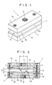
- the first component 1 and the second component 2 are fixed with bolts 4 and 4 via a spacer 3 as shown in FIG. 1 through FIG. 3.
- nozzle plates 1 and 2b are mounted on main bodies 1a and 2a with bolts 4 and 7 and bolts 4 and 8 via sealing materials, e.g., O rings 5 and 6.
- the main bodies 1a and 2a are provided with connection holes 1 and 2c, and the nozzle plates 1b and 2b are provided with fluid conduits 1 and 2d.
- the fluid conduits 1d and 2d are opened in the inner walls 1e and 2e of the nozzle plates 1 b and 2b.
- the inner walls 1 e and 2e of the nozzle plates 1 b and 2b and the axes A L1 and A L2 of the fluid conduits 1 and 2d form a yarn treating region R T for interlacing a yarn.
- the fluid conduits 1d and 2d are spaced away from each other by the distance E (see FIG. 2) defined by the axes A L1 and A L2 and they are inclined so that they eject fluid toward the yarn treating region R T .
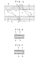
- an auxiliary line L A which passes through an intersection P of the diagonal line and which is orthogonal with the inner walls 1 and 2e of the nozzle plates 1 and 2b is drawn in the parallelogrammatic yarn treating region R T of FIG. 4.
- the distance from the point at which the axis A L1 of the fluid conduit 1 intersects with the inner wall 1 e of the nozzle plate 1 b to the auxiliary line L A is defined as L 1 and the distance from the point at which the axis A L1 of the fluid conduit 1d intersects with the inner wall 2e of the nozzle plate 2b to the auxiliary line L A is defined as L 2 .
- an angle ⁇ formed by the inner walls, which constitute the major part of the yarn treating region R T (see FIG. 4), and the axes A L1 and A L2 is 90 or less.
- the yarn consisting of a multifilament running through the yarn treating region R T usually exhibits lateral chord vibration in FIG. 2.
- the yarn to be interlaced behaves two-dimensionally due to the fluid ejecting from the fluid conduit 2d and deflects toward the fluid conduit 1d located outside, the yarn will be drawn back into the central yarn treating region R T by the fluid which ejects from the fluid conduit 1d. The same effect applies when the yarn deflects toward the fluid conduit 2d.
- the yarn running through the yarn treating region R T exhibits extremely self-stable chord vibration behavior in which it shuttles between the fluid conduit 1d and the fluid conduit 2d.
- the yarn which is interlaced laterally vibrates through the yarn treating region R T between the fluid conduits 1d and 2d in FIG. 2 and it is effectively provided with opened portions and interlaced portions by the fluid ejected from the fluid conduits 1d and 2d, thereby turning into a yarn with a high level of coherence.
- the second component 2 has a long inserting hole 2f for inserting the bolts 4 of the main body 2a and the nozzle plate 2b. This makes it possible to adjust a distance E (see FIG. 2) between the axes A L1 and A L2 of the fluid conduits 1 and 2d in the horizontal direction in the apparatus of this embodiment.
- pressurized air is supplied to the connection holes 1d and 2d from a fluid supplying source like a pressurized air source, not shown, while allowing the yarn, which is to be interlaced, to run through the gap formed by the first and second components 1 and 2. Then the pressurized air passes through the fluid conduits 1 d and 2d and ejects as shown by the arrowheads in FIG. 2.
- the yarn is effectively interlaced by the pressurized air, which ejects out through the fluid conduits 1 and 2d, in the yarn treating region R T while it runs between the first and second components 1 and 2.
- the pressurized air ejected from the fluid conduits 1d and 2d bumps against the inner walls 1 e and 2e of the facing nozzle plates 1 b and 2b without bumping against each other, then it is discharged out of the apparatus along the inner walls 1e and 2e of the nozzle plates 1b and 2b.
- the pressurized air is discharged, it is rapidly discharged with a high density because there is no obstacles blocking its discharge except the yarn.
- the pressurized air ejected from the fluid conduits 1 and 2d is allowed to maintain its own high potential energy, thus permitting effective use of the dynamic pressure owned by the pressurized air for interlacing the yarn.
- the pressurized air for interlacing the yarn is dense in the area where it has ejected from the fluid conduits 1 and 2d but sparse in the adjoining areas in the section shown in FIG. 2.
- the presence of the sparse, dense, and sparse areas of the pressurized air further makes it easy to form opened and interlaced portions of the yarn, ensuring effective interlacing of the yarn.
- a gap G (see FIG. 2) between the components 1 and 2 can be changed by adjusting the thickness of a spacer 3.
- At least one each of the fluid conduits 1 and 2d may be provided in each of the components 1 and 2, and the distance E in the horizontal direction between the fluid conduits 1d and 2d varies depending on the gap G between the first and second components 1 and 2, which face against each other, and the type of yarn to be interlaced.
- the fluid conduits 1d and 2d have, for example, a round section, however, the configuration is not limited to the round section; it is needless to say that its configuration may alternatively be an ellipse or a polygon such as a triangle or quadrangle.
- the major part, which constitutes the yarn treating region R T , of inner walls 1e and 2e of the nozzle plates 1b and 2b facing against each other has a flat plane.
- the loss in the energy of the pressurized air ejected from the fluid conduits 1d and 2d is minimized and the dynamic pressure of the ejecting pressurized air can be effectively used for interlacing.
- the fluid conduits 1d and 2d provided in the nozzle plates 1 b and 2b of the first and second components 1 and 2 are oriented so that they are orthogonal with the yarn running direction as shown by the arrowhead in FIG. 6 in the section in the yarn running direction.
- the fluid conduits 1d and 2d are oriented aslant to the yarn running direction shown by the arrowhead in FIG. 7.
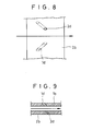
- the fluid conduits 1 and 2d are made so that the pressurized air is ejected in the yarn running direction as shown by the arrowhead in FIG. 8 which shows the nozzle plate 2b observed from above.
- FIG. 6 and FIG. 7 give schematic models used for the purpose of clearly showing the direction of the inclination of the fluid conduits 1 and 2d in the section in the yarn running direction. The same applies to FIG. 9, FIG. 16 through FIG. 19, FIG. 21, FIG. 28 through FIG. 32 and FIG. 34.
- the same effect can be obtained when the fluid conduit 1 d of the fluid conduits 1 and 2d is oriented in the yarn running direction or when the fluid conduit 2d is oriented in the downstream side with respect to the yarn running direction as shown by the arrowhead.
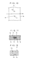
- the nozzle plates 1 and 2b, which constitute the inner walls 1e and 2e of the first and second components 1 and 2 are provided with projecting walls 1g and 2g which juts out toward their associated nozzle plates 1 and 2b at the portions adjacent to the surface which constitutes the major part for forming the yarn treating region R T in the section orthogonal with the yarn running direction as shown in FIG. 11.
- the nozzle plates 1 b and 2b may be made into one piece and a cylindrical nozzle component 9 with fluid conduits 9a and 9a opened in a central yarn running space 9b may be used.
- the fluid conduits 9a and 9a are provided with a gap between their axes and are inclined so that the fluid is jetted out toward the yarn running space 9b which serves as the yarn treating region. This should help reduce the number of components that make up the apparatus for treating yarn with fluid.
- the diameter of the fluid conduits 1 and 2d was set to 1.6 mm
- the horizontal distance E between the axes A L1 and A L2 of the fluid conduits 1 and 2d was set to 5 mm
- the gap G between the nozzle plates 1 b and 2b was set to 2 mm
- the angle ⁇ of the fluid conduits 1 and 2d inclined against the nozzle plates 1b and 2b was set to 60 °
- a nylon yarn consisting of 420 deniers and 72 filaments was allowed to run at a yarn speed of 1,000 m/min.
- the treating tension of the nylon yarn was 20 g ⁇ f before it was subjected to the treating apparatus and 50 g ⁇ f after it was subjected to the interlacing.
- the monofilaments constituting the nylon yarn were effectively provided with opened and interlaced portions, producing a yarn which features a high level of coherence, i.e., 28 firm interlaced portions per meter.
- the diameter of the fluid conduits 1d and 2d was set to 1.0 mm
- the horizontal distance E between the axes A L1 and A L2 of the fluid conduits 1 d and 2d was set to 7.4 mm
- the gap G between the nozzle plates 1 b and 2b was set to 2 mm
- the angle ⁇ of inclination of the fluid conduits 1d and 2d with respect to the nozzle plates 1 b and 2b was set to 30°
- a Tetoron yarn of 75 deniers, consisting of 36 filaments was allowed to run at a yarn speed of 1,000 m/min., with a treating tension of 5 g ⁇ f applied to the yarn, to interlace the yarn by ejecting pressurized air of 6 kg/cm 2 ⁇ G from the fluid conduits 1 and 2d.
- Tetoron yarn of 75 deniers consisting of 36 filaments was subjected to the interlacing process under the same treatment conditions, using the yarn treating apparatus shown in FIG. 36.
- the monofilaments of the Tetoron yarn interlaced by using the apparatus of the present example were effectively provided with opened and interlaced portions, and had 16.3 firm interlaced portions per meter.
- the Tetoron yarn interlaced using the apparatus shown in FIG. 36 had only 12.0 firm interlaced portions per meter.
- the first component 11 and the second component 12 are fixed with bolts 14 and 14 via a spacer 13.
- the nozzle plates 11b and 12b of the first component 11 and the second component 12 are mounted on main bodies 11 a and 12a with bolts 14, 17 and bolts 14, 18 via sealing materials, e.g., O rings 15 and 16.
- the main bodies 11 a and 12a are provided with connection holes 11 and 12c.
- the nozzle plates 11b and 12b are provided with a sub fluid conduit 11 d and a fluid conduit 11 e and a sub fluid conduit 12d and a fluid conduit 12e which are opened in the inner walls 11f and 12f and which are in parallel to each other.
- the sub fluid conduits 11 d and 12d are inclined against the nozzle plates 11b and 12b by the angle ⁇ and are oriented so that they face against each other with their axes aligned.
- the fluid conduits 11 e and 12e form the yarn treating region R T for interlacing yarn with the axes A L11 and A L12 and the inner walls 11f and 12f of the nozzle plates 11b and 12b.
- the fluid conduits 11 e and 12e are provided with a gap between the axes A L11 and A L12 and are inclined so that the fluid is ejected toward the yarn treating region R T .
- the sub fluid conduits 11d and 12d and the fluid conduits 11 e and 12e are arranged so that the angle ⁇ formed by the inner walls 11f and 12f of the nozzle plates 11b and 12b, which inner walls 11f and 12f constitute the major part for producing the yarn treating region R T , and the axes A L11 and A L12 becomes 90 ° or less.
- pressurized air is supplied to the connection holes 11 c and 12c from a fluid supplying source like a pressurized air source, not shown, while allowing the yarn, which is to be interlaced, to run through the gap formed by the nozzle plates 11b and 12b. Then, the pressurized air passes through the sub fluid conduits 11d and 12d and fluid conduits 11 and 12e, then it ejects out aslant toward the nozzle plates 11 b and 12b facing against each other.
- the yarn vibrates two-dimensionally while it runs and it is effectively interlaced in the yarn treating region R T by the pressurized air ejected from the sub fluid conduits 11d and 12d and the fluid conduits 11 and 12e. Since the sub fluid conduits 11d and 12d and the fluid conduits 11 e and 12e are located aslant to the nozzle plates 11 b and 12b, the ejecting pressurized air bumps aslant against the running yarn. This increases the chances of the yarn crossing the pressurized air, leading to high coherence of the yarn.
- the gap G (see FIG. 14) between the components 11 and 12 can be changed by adjusting the thickness of a spacer 13 in accordance with the type of yarn to be interlaced.
- each of the sub fluid conduits 11 d and 12d, which face against each other, may be provided at least one in each of the nozzle plates 11 b and 12b.
- each of the fluid conduits 11 and 12e may be provided at least one in each of the nozzle plates 11b and 12b.
- the horizontal distance between them varies depending on the gap G between the first and second components 11 and 12, which face against each other, and the type of yarn to be interlaced.
- the sub fluid conduits 11d and 12d and the fluid conduits 11 and 12e have, for example, a round section, however, the configuration is not limited to the round section; it is needless to say that its configuration may be an ellipse or a polygon such as a triangle or quadrangle.
- the major part, which constitutes the yarn treating region R T , of inner walls 11f and 12f of the nozzle plates 11 b and 12b facing against each other has a flat plane.
- the loss in the energy of the pressurized air ejected from the sub fluid conduits 11d and 12d is minimized and the dynamic pressure of the ejecting pressurized air can be effectively used for interlacing.
- a horizontal displacement e 1 of the fluid conduit 11 e with respect to the fluid conduit 11 d and a horizontal displacement e 2 of the fluid conduit 12e with respect to the fluid conduit 12d are set to a value between 1.5 times and 6 times, preferably between 2 times and 4 times the inner diameter, do, of the sub fluid conduits 11d and 12d.
- the sub fluid conduits 11d and 12d and the fluid conduits 11 and 12e provided in the nozzle plates 11b and 12b of the first and second components 11 and 12 are oriented so that they are substantially orthogonal with the yarn running direction shown by the arrowhead in the section in the yarn running direction as shown in FIG. 16 or they are inclined against the yarn running direction shown by the arrowhead in FIG. 17 and FIG. 18.
- the sub fluid conduit 11d and the fluid conduits 11 and 12e may inclined so that the pressurized air is ejected in the yarn running direction and the sub fluid conduit 12d may be inclined so that the pressurized air is ejected in the opposite direction from the yarn running direction.
- FIG. 20 which illustrates the opening of the fluid conduits 12d and 12e of the nozzle plate 12b observed from above, the sub fluid conduits 11d and 12d and the fluid conduit 11 are located in parallel to each other, while the fluid conduit 12e is located axially symmetrical to the fluid conduit 11 e with respect to the line indicated by the arrowhead showing the yarn running direction.
- the sub fluid conduit 11 d and the fluid conduits 11 e and 12e may be inclined so that the pressurized air is ejected in the opposite direction from the yarn running direction, while the sub fluid conduit 12d is inclined so that the pressurized air is ejected in the yarn running direction.
- the sub fluid conduit 12d is inclined so that the pressurized air is ejected in the yarn running direction.
- the diameter of the sub fluid conduits 11d and 12d and the fluid conduits 11 and 12e was set to 1.6 mm
- the horizontal distance between the axes of the adjoining fluid conduits 11d, 11 and fluid conduits 12d, 12e, that is, the displacements ei, e 2 were set to 5 mm
- the gap G between the nozzle plates 11 b and 12b was set to 2 mm
- the angle ⁇ of the sub fluid conduits 11d, 12d and the fluid conduits 11e, 12e inclined against the nozzle plates 11 b and 12b was set to 60°
- a nylon yarn consisting of 420 deniers and 72 filaments was allowed to run at a yarn speed of 1,000 m/min. to interlace the yarn by ejecting a pressurized air
- the monofilaments constituting the nylon yarn were effectively provided with opened and interlaced portions, producing a yarn which features a high level of coherence, i.e., 27 to 34 firm interlaced portions per meter and the yarn was effectively prevented from jumping out of the fluid conduits 11 and 12e during the interlacing process.
- the diameter of the sub fluid conduits 11 d and 12d and the diameter of the fluid conduits 11 e and 12e were individually set to 1.0 mm
- the displacement e 1 between the axes of the adjoining fluid conduits 11d, 11 and the displacement e 2 between the axes of the adjoining fluid conduits 12d, 12e were set to 1.5 mm
- the gap G between the nozzle plates 11 b and 12b was set to 2 mm
- the angle ⁇ of inclination of the sub fluid conduits 11d, 12d and the fluid conduits 11e, 12e with respect to the nozzle plates 11 and 12b was set to 60°.
- a Tetoron yarn of 300 deniers consisting of 96 filaments was subjected to the interlacing process under the same treatment conditions, using the yarn treating apparatus shown in FIG. 36.
- pressurized air was ejected at 6 kg/cm 2 ⁇ G for the interlacing process.
- the monofilaments of the Tetoron yarn interlaced by using the apparatus of the present example were effectively provided with opened and interlaced portions, and had 27.0 firm interlaced portions per meter.
- the Tetoron yarn interlaced using the apparatus shown in FIG. 36 had only 13.5 firm interlaced portions per meter.
- the first component 21 and the second component 22 are fixed with bolts 24 and 24 via a spacer 23.
- the nozzle plates 21 b and 22b of the first component 21 and the second component 22 are mounted on main bodies 21 a and 22a with bolts 24, 27 and bolts 24, 28 via sealing materials, e.g., O rings 25 and 26.
- the main bodies 21 a and 22a are provided with connection holes 21 c and 22c, while the nozzle plates 21 b and 22b are provided with a plurality of fluid conduits 21 d and 22d.
- a plurality of fluid conduits 21 d and 22d are opened in the inner walls 21f and 22f (see FIG. 25) of the nozzle plates 21 b and 22b, respectively, as shown in FIG. 24, and they are arranged so that they face against each other and they are inclined against each other.
- the plurality of fluid conduits 21 d and 22d are laid out in parallel between the axes L A of adjoining fluid conduits with specified intervals.
- the fluid conduits 21 d 2 through 21d 6 and 22d, through 22d 5 are provided so that the axes of the fluid conduits 21 d 2 through 21d 6 and 22d, through 22d 5 are inclined by an acute angle 0 against the nozzle plate 22b as shown in FIG. 27 cut with a plane which is orthogonal with the running direction of a yarn T. Inclining the fluid conduits like this makes it easier for the yarn to laterally vibrate by the ejecting fluid, leading to enhanced interlacing performance.
- each single yarn exhibits lateral chord vibration in the cross section of the apparatus, for example, shown in FIG. 27 and they are interlaced with each other.
- the axes L A21 and L A22 of the fluid conduits 21 d and 22d located on the outermost side of the plurality of fluid conduits 21 d and 22d and the nozzle plates 21 b and 22b form a wide yarn treating region between the nozzle plates 21 b and 22b for interlacing the yarn.
- the second component 22 has an elliptic inserting hole 22e in which a bolt 24 of a main body 22a and the nozzle plate 22b is inserted. This makes it possible to slightly adjust the arranging direction of the fluid conduits 21 d and 22d which face against each other in the apparatus 20 of this embodiment.
- pressurized air is supplied to connection holes 21 c and 22c from a fluid supplying source like a pressurized air source, not shown, while allowing the yarn, which is to be interlaced, to run through the gap formed by the first and second components 21 and 22. Then the pressurized air passes through a plurality of the fluid conduits 21 d and 22d and ejects out.
- the yarn is interlaced by the pressurized air which ejects out through the fluid conduits 21 d and 22d facing against each other.
- the gap G (see FIG. 24) between the components 21 and 22 can be changed by adjusting the thickness of the spacer 23.
- the fluid conduits 21 d and 22d have, for example, a round section, however, the configuration is not limited to the round section; it is needless to say that its configuration may be an ellipse or a polygon such as a triangle or quadrangle.
- the said plurality of fluid conduits 21 d and 22d are provided with their axes displaced so that the fluid conduits 21 d and 22d facing against each other share a common area where they overlap in a plane of projection which is perpendicular to the axial direction of the fluid conduits 21 d and 22d.
- the axis L A21 of the fluid conduits 21 d provided in the nozzle plate 21 b and the axis L A22 of the corresponding fluid conduit 22d provided in the nozzle plate 22b are horizontally displaced.
- the displacement "e” depends on the horizontal distance between the corresponding fluid conduits 21 d and 22d and the size of the fluid conduits. More preferably, the displacement "e” is set so that the projection area in the plane of projection perpendicular to the axial direction ranges from 50% to 100%.
- the inner walls 21f and 22f of the nozzle plates 21 b and 22b in which a plurality of fluid conduits 21 d and 22d are opened have flat surfaces.
- the fluid conduits opened in the first and second components 21 and 22 may be provided so that the fluid conduits 21 d and 22d facing against each other are substantially orthogonal with the running direction of the yarn T as shown in FIG. 28 wherein the nozzle plates 21 b and 22b are cut along the running direction of the yarn T, or they may be provided in the running direction of the yarn T with intervals given between them as shown in FIG. 29.
- the fluid conduits 21 d and 22d may be formed such that each pair of fluid conduits 21 d and 22d, aligned with each other, extends aslant with respect to the running direction of the yarn T.
- the fluid conduits 21 d and 22d may be laid out in such a manner that adjacent pairs of fluid conduits 21 d and 22d, individually aligned with each other, extend crossways in different directions, as shown in FIG. 32.
- the aforesaid first and second components 21 and 22 are provided with additional fluid conduits 21 g and 22g, one each, for ejecting a fluid to a running yarn, the additional fluid conduits 21 g and 22g being located outside the plurality of fluid conduits 21 d and 22d.
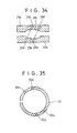
- first and second components 21 and 22 may be provided with recesses 21 h and 22h, between which the yarn runs, the recesses being made in the inner walls of the nozzle plates 21 b and 22b as shown in FIG. 34 which illustrates the components cut by a plane orthogonal with the yarn running direction.
- the nozzle plates 21 b and 22b may be combined into a cylindrical nozzle component 30 which has a C-shape cross section, and a fluid may be ejected from a plurality of fluid conduits 30a to interlace the yarn, the fluid conduits being provided in the nozzle component 30 and facing against each other.
- the diameter of the fluid conduits 21 d and 22d was set to 1.6 mm
- the horizontal distance between the adjoining fluid conduits 21 d and 21 d and between adjoining fluid conduits 22d and 22d were set to 5 mm
- the gap G between the nozzle plates 21 and 22b was set to 10 mm
- the displacement "e" of the fluid conduits 21 d and 22d facing against each other was set to 0 mm, 0.8 mm, and 2.5 mm
- a flat tow yarn of 64,000 deniers and 64,000 filaments was allowed to run at a yarn speed of 4 m/min. to interlace the yarn by ejecting a pressurized air of 2 kg/cm2. G from the fluid conduits 21 d and 22d.
- the yarn was provided with interlaced portions, where the filaments were interlaced partially, and opened portions which are free of interlacing, and the interlaced portions were overlapped widthwise, thus providing the yarn with coherence wherein the yarn was interlaced as flat meshes of a net as a whole.
- the interlaced portions were not bundled roundly, which used to be a problem with the interlacing performed by the conventional apparatuses, thus proving improved coherence.
Landscapes
- Physics & Mathematics (AREA)
- Fluid Mechanics (AREA)
- Engineering & Computer Science (AREA)
- Textile Engineering (AREA)
- Yarns And Mechanical Finishing Of Yarns Or Ropes (AREA)
- Treatment Of Fiber Materials (AREA)
Abstract
Description
- The present invention relates to an apparatus for interlacing the filaments of a yarn, which consists of a multifilament, by the effect of a fluid, thereby providing the yarn with high coherence.
- A yarn consisting of an as-spun or zero twist multifilament is interlaced mainly because of its difficult handling due to poor coherence.
- As an apparatus for interlacing an as-spun yarn by the effect of a fluid, the ones disclosed under US Patent No. 3,115,691, Unexamined Japanese Patent Publication (KOKAI) No. 61-194243, and Unexamined Japanese Patent Publication No. 59-66532 are known.
- In these treating apparatuses, the one disclosed in US Patent No. 3,115,691, for example, as shown in FIG. 36, which is a cross-sectional drawing orthogonal with the yarn running direction, one component B1 of the two components B1 and B2, which interlace yarn, is provided with fluid conduits P1 and Pi, which are inclined against each other toward the inner wall of the other component B2. Or as shown in FIG. 37 which is a similar cross-sectional drawing, one component B1 is provided with fluid conduits P2 and P2, which eject a fluid toward the inner wall of the other component B2, so that they are in parallel to each other and are orthogonal with the inner wall.
- Further in this treating apparatus, a yarn to be interlaced is allowed to run between the components B1 and B2, and a fluid is ejected from the fluid conduits P1 and P1 toward the other component B2, thus interlacing the yarn by the effect of the fluid. The fluid conduits are provided only in one of the components.
- In addition, a treating apparatus which has two facing components, each thereof being provided with an fluid conduit, is disclosed in FIG. 3 and FIG. 38 of US Patent No. 2,985,995. Both these apparatuses have a pair of facing fluid conduits which share a common axis and produce a colliding jet which interlaces the fibers constituting the multifilament yarn.
- In these conventional apparatuses, how frequently the multifilament yarn is exposed to the colliding jet produced by the facing fluid conduits is an important key for achieving efficient treating apparatuses, and the geometric configurations and actual dimensions of the inner wall surfaces of the two components, which configure the yarn treating region, are therefore important.
- In the treating apparatus described above, the yarn is interlaced by a fluid ejected from the fluid conduits provided in one of the two components. Therefore, the yarn to be treated is interlaced while it vibrates two-dimensionally between the two fluid conduits. Hence, it is necessary to enhance the frequency of the exposure of the yarn, which is to be interlaced, to the fluid ejected from the fluid conduits, the resulting coherence of the yarn depending on the exposure frequency.
- In the conventional treating apparatus shown in FIG. 11 and FIG. 12 of US Patent No. 3,115,691 described above, the yarn, which is interlaced by the fluid ejected from the fluid conduits, tends to jump out of the ejecting fluid because of the two- dimensional vibration, presenting a problem that the yarn partially misses interlacing.
- Furthermore, in the aforesaid conventional colliding jet type apparatus, the filaments constituting the multifilament yarn are positively exposed to the colliding jet by contacting with and bouncing against the inner wall of the two components.
- Hence, the material and surface treatment condition significantly influence the quality factors of yarn such as frays, strength, and elongation percentage.
- Therefore, (1) the apparatus is not suited for a yarn manufacturing process for semi-drawn yarns, such as POY (pre-oriented yarn), tire cords or the like for which maximum efforts should be made to avoid causing deterioration in yarn quality.
- In addition, (2) the apparatus is not capable of providing wide, flat yarns such as staple and tow with coherence while maintaining their flatness intact because the flatness is crushed at interlaced points.
- Especially, the apparatus disclosed in FIG. 3 and FIG. 38 of US Patent No. 2,985,995 is intended to provide a multifilament yarn with coherence (interlacing). However, it is not designed to interlace flat yarns such as staple and tow while maintaining their flatness intact. More specifically, in this apparatus, the yarn after it is interlaced presents an approximately circular cross section; therefore, the apparatus has a disadvantage in that it cannot maintain the original flatness of the yarn.
- Also, since the fluid ejected from the fluid conduits is used for interlacing yarns, it is necessary to accomplish the most effective use of the potential energy, i.e., the dynamic pressure, that the fluid has.
- The conventional treating apparatuses, however, are not satisfactory in the aspects of increasing the frequency of exposing yarn to the fluid and of the efficient use of the dynamic pressure of the fluid.
- Furthermore, Examined Japanese Utility Model Publication (KOKOKU) No. 52-44689 discloses a treating apparatus which uses the same components facing against each other and has a plurality of fluid conduits, but the axes of the fluid conduits are not shared or crossed.
- This apparatus, however, is designed to twist a yarn by positively generating a revolving stream in a treating region, which has a circular cross section, and therefore it provides a multifilament yarn, which continuously runs, with false-twisting. Accordingly, the apparatus utterly differs, in the objects and the obtained form of yarn, from the treating apparatus designed to provide a yarn with coherence which is an object of the present invention.
- The first object of the present invention is to provide an apparatus for treating yarn with fluid suited for a yarn manufacturing process which needs to avoid causing deterioration in yarn quality as much as possible.
- The second object of the present invention is to provide an apparatus for treating yarn with fluid which is capable of interlacing flat yarns consisted of a multifilament while maintaining their flatness intact.
- A common object of the present invention is to provide an apparatus for treating yarn with fluid which is designed to restrain a yarn to be interlaced from jumping out of the fluid ejected from fluid conduits, thereby increasing the frequency of the exposure of the yarn to the fluid and presenting good interlacing performance.
- A further object of the present invention is to provide an apparatus for treating yarn with fluid which is designed to utilize the dynamic pressure of the fluid, which interlaces yarns, as effectively as possible, thereby enhancing the efficiency of the use of the dynamic pressure which the fluid has.
- To accomplish the above-mentioned objects, the inventors observed the relationships obtained between the fluid ejected from fluid conduits and the yarns interlaced by the fluid, with different layouts of the fluid conduits, and carefully studied the relationships from the viewpoint of the layout of the fluid conduits.
- The inventors discovered a fact that the best result is obtained when the axes of the fluid conduits formed in both the first and second components are shifted against each other and inclined against each component so that the fluid is ejected toward a yarn treating region, which is formed in a section substantially orthogonal with the yarn running direction.
- To be specific, when the fluid conduits formed both in the first and second components are arranged as described above, the fluid ejected from these fluid conduits and the inner walls of the first and second components form a yarn treating region. The inventors found that when a yarn consisting of an as-spun multifilament is allowed to pass through the yarn treating region, the encountering frequency of the yarn and the fluid increases in interlacing the filaments, the coherence of the yarn improves and the yarn is effectively restrained from jumping out of the yarn treating region, thus permitting effective utilization of the dynamic pressure of the fluid.
- The present invention has been accomplished based on the knowledge described above. According to the first invention of the present invention, an apparatus for treating yarn with fluid which is designed to allow a yarn consisting of an as-spun multifilament to run between first and second components, which have inner walls arranged facing against each other with a specified gap provided between them, and to interlace said filaments by a fluid in order to provide said yarn with coherence, wherein said first and second components are provided with at least one fluid conduit opened in each of said inner walls, said fluid conduits form a yarn treating region with axes of said fluid conduits and said inner walls of said first and second components, a specified distance is provided between said axes of said fluid conduits in a section which is substantially orthogonal with a running direction of said yarn, and said fluid conduits are inclined so that said fluid ejected from said fluid conduits is directed toward said yarn treating region.
- According to the apparatus described above, the yarn to be interlaced does not jump out of the yarn treating region and the frequency of encounter between the yarn and the fluid is increased, resulting in good yarn interlacing performance.
- Further according to the apparatus described above, the quality of the yarn to be interlaced is not deteriorated.
- Still further according to the apparatus described above, the fluid ejecting from the fluid conduits is directed toward the yarn treating region, permitting effective utilization of the dynamic pressure of the fluid.
- Preferably, said inner walls of said first and second components have flat surfaces which constitute a major part of said yarn treating region.
- Further preferably, said fluid conduits are oriented so that they are substantially orthogonal with said running direction of said yarn in a section in said running direction of said yarn.
- Still preferably, said fluid conduits are located aslant to said running direction of said yarn in a section in said running direction of said yarn.
- Yet preferably, said inner walls of said first and second components are provided with projections which jut out toward their associated inner walls at a portions adjoining to said major part constituting said yarn treating region in a section which is substantially orthogonal with said running direction of said yarn.
- Preferably, said first and second components are provided with at least one sub fluid conduit for ejecting a fluid to said yarn treating region, which sub fluid conduits are provided between axes of said fluid conduits and which are arranged in parallel to and face against said fluid conduits in a section which is substantially orthogonal with said running direction of said yarn.
- Further preferably, said inner walls of said first and second components have flat surfaces which constitute said major part of said yarn treating region.
- Preferably, said fluid conduits and sub fluid conduits are oriented so that they are substantially orthogonal with said running direction of said yarn in a section in said running direction of said yarn.
- Preferably, said fluid conduits and sub fluid conduits are located aslant to said running direction of said yarn in a section in said running direction of said yarn.
- In addition, according to the second invention of the present invention, an apparatus which is designed to allow a yarn consisting of an as-spun multifilament to run between first and second components which have inner walls located facing against each other with a specified gap provided between them and to interlace said filaments with each other by a fluid, thereby providing said yarn with coherence, wherein said first and second components are provided with a plurality of fluid conduits for ejecting said fluid in a section, which is substantially orthogonal with a running direction of said yarn, said fluid conduits are opened in said respective inner walls, arranged facing against each other, and formed between axes of adjoining fluid conduits in parallel with a specified distance provided between them.
- According to the apparatus described above, an effect is obtained which makes it possible to interlace a flat yarn while maintaining its flatness intact in addition to the effect provided by the first embodiment present invention.
- Preferably, said plurality of fluid conduits are provided with their axes displaced so that said fluid conduits facing against each other share an overlapping area in a plane of projection which is perpendicular to said axial directions of respective fluid conduits.
- Further preferably, a size of said common area ranges from 50% to 100% of said projected area of said respective fluid conduits.
- Preferably, said inner walls, in which said plurality of fluid conduits are opened, of said first and second components are flat surfaces.
- Further preferably, each of said first and second components has an additional fluid conduit for jetting said fluid toward said yarn, which additional fluid conduit is provided outside said plurality of fluid conduits facing against each other.
- According to a preferable aspect described above, the performance of the apparatus according to the present invention described above is further improved.
- The above and other objects, characteristics, and advantages of the present invention will become more apparent from the following detailed description taken in connection with the accompanying drawings.
-
- FIG. 1 is a perspective view of an apparatus for treating yarn with fluid related to the first embodiment of the first invention of the present invention;
- FIG. 2 is a front view which shows the section of the apparatus of FIG. 1;
- FIG. 3 is a left side view of the apparatus of FIG. 1 ;
- FIG. 4 is an enlarged view which shows the relationship between the fluid conduits provided in the nozzle plates of the apparatus for treating yarn with fluid and a yarn treating region;
- FIG. 5 is an enlarged view which shows the fluid conduits provided in the nozzle plates of the apparatus, the orientation of the fluid conduits being opposite from that shown in FIG. 4;
- FIG. 6 is a cross-sectional view which schematically shows the fluid conduits which are provided in the nozzle plates of the apparatus and which are oriented so that they are substantially orthogonal with the yarn running direction in the section of the yarn running direction;
- FIG. 7 is a cross-sectional view which schematically shows the fluid conduits which are provided in the nozzle plates of the apparatus and which are inclined against the yarn running direction;
- FIG. 8 is an arrangement drawing of the fluid conduits when the nozzle plate of the second component is viewed from above under the condition of FIG. 7;
- FIG. 9 is an another cross-sectional view which schematically shows the fluid conduits which are provided in the nozzle plates of the apparatus and which are inclined against the yarn running direction in the section of the yarn running direction;
- FIG. 10 is an arrangement drawing of the fluid conduits when the nozzle plate of the second component is viewed from above under the condition of FIG. 9;
- FIG. 11 is a cross-sectional view showing a modification of the nozzle plates of the apparatus;
- FIG. 12 shows another modification of the nozzle plate of the apparatus and it is a cross-sectional view of a nozzle component which is made integral with the nozzle plates;
- FIG. 13 is a perspective view of the apparatus for treating yarn with fluid related to the second embodiment of the first invention of the present invention;
- FIG. 14 is a front view showing a section of the apparatus of FIG. 13;
- FIG. 15 is a left side view of the apparatus of FIG. 13;
- FIG. 16 is a cross-sectional view which schematically shows the fluid conduits which are provided in the nozzle plates of the apparatus and which are laid out so that they are substantially orthogonal with the yarn running direction in the section of the yarn running direction;
- FIG. 17 is a cross-sectional view which schematically shows the fluid conduits which are provided in the nozzle plates of the apparatus and which are inclined backward against the yarn running direction;
- FIG. 18 is a cross-sectional view which schematically shows the fluid conduits which are provided in the nozzle plates of the apparatus and which are inclined forward against the yarn running direction;
- FIG. 19 is a cross-sectional view which schematically shows another example wherein the fluid conduits provided in the nozzle plates of the apparatus are inclined against the yarn running direction;
- FIG. 20 is an arrangement drawing of the fluid conduits when the nozzle plate of the second component is viewed from above under the condition of FIG. 19;
- FIG. 21 is a cross-sectional view which schematically shows another example wherein the fluid conduits provided in the nozzle plates of the apparatus are inclined against the yarn running direction;
- FIG. 22 is an arrangement drawing of the fluid conduits when the nozzle plate of the second component is viewed from above under the condition of FIG. 21;
- FIG. 23 is a perspective view of the apparatus for treating yarn with fluid related to the second invention of the present invention;
- FIG. 24 is a front view of the section of the apparatus of FIG. 23;
- FIG. 25 is a left side view of the apparatus of FIG. 23;
- FIG. 26 is a cross-sectional view which illustrates the displacement of the fluid conduits provided in the nozzle plates of the apparatus in the plane orthogonal with the yarn running direction;
- FIG. 27 is a cross-sectional view which illustrates the inclination of the fluid conduits provided in the nozzle plates of the apparatus in the plane orthogonal with the yarn running direction;
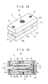
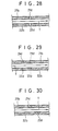
- FIG. 28 is a cross-sectional view which schematically shows the fluid conduits which are provided in the nozzle plates of the apparatus and which are oriented so that they are substantially orthogonal with the yarn running direction in the section of the yarn running direction;
- FIG. 29 is a cross-sectional view which schematically shows the fluid conduits which are provided in the nozzle plates of the apparatus and which are provided with gaps between them with respect to the yarn running direction;
- FIG. 30 is a cross-sectional view which schematically shows the fluid conduits which are provided in the nozzle plates of the apparatus and which are provided aslant to the yarn running direction in the section of the yarn running direction;
- FIG. 31 is a cross-sectional view which schematically shows the fluid conduits which are provided in the nozzle plates of the apparatus and which are inclined against the yarn running direction;
- FIG. 32 is a cross-sectional view which schematically shows the fluid conduits which are provided in the nozzle plates of the apparatus and which are inclined against each other with respect to the yarn running direction;
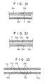
- FIG. 33 is a cross-sectional view which schematically shows fluid conduits which have been added outside a plurality of fluid conduits provided in the apparatus;
- FIG. 34 is a cross-sectional view which schematically shows a case wherein the fluid conduits provided in the nozzle plates of the apparatus are opened in a recess formed in the yarn running direction;
- FIG. 35 is a cross-sectional view which shows a case wherein the nozzle plate of the apparatus is made of a single C-shaped cylindrical nozzle component;
- FIG. 36 is a cross-sectional view which shows a conventional apparatus for treating yarn with fluid wherein the fluid conduits provided in one component are arranged aslant; and
- FIG. 37 is a cross-sectional view which shows a conventional apparatus wherein the fluid conduits provided in one component are in parallel to each other and orthogonal with the inner wall.
- The following gives detailed explanation of the first embodiment of the first invention of the present invention with reference to FIG. 1 through FIG. 12.
- In the apparatus for treating yarn with fluid of the embodiment, the
first component 1 and thesecond component 2 are fixed withbolts spacer 3 as shown in FIG. 1 through FIG. 3. - As shown in FIG. 2 illustrating a section which is substantially orthogonal with the running direction of a yarn, in the
first component 1 and thesecond component 2,nozzle plates main bodies bolts bolts main bodies connection holes nozzle plates fluid conduits - As shown in FIG. 4, the
fluid conduits inner walls nozzle plates inner walls nozzle plates fluid conduits fluid conduits - The following presents further details of the
inclined fluid conduits - For example, regarding the
fluid conduit 1d, an auxiliary line LA which passes through an intersection P of the diagonal line and which is orthogonal with theinner walls nozzle plates - The distance from the point at which the axis AL1 of the
fluid conduit 1 intersects with theinner wall 1 e of thenozzle plate 1 b to the auxiliary line LA is defined as L1 and the distance from the point at which the axis AL1 of thefluid conduit 1d intersects with theinner wall 2e of thenozzle plate 2b to the auxiliary line LA is defined as L2. - At this time, if the
fluid conduit 1d is formed so that the distances L1 and L2 have a relationship of L1 > L2, then the fluid ejected from thefluid conduit 1d will be directed toward the yarn treating region RT. - The aforementioned relationship L1 > L2 is true with the
fluid conduit 2d, and it is also true with the second embodiment related to the first invention and the second invention of the present invention to be explained below. - Hence, as shown in FIG. 2, regarding the
fluid conduits nozzle plates - In the apparatus for treating yarn with fluid, the yarn consisting of a multifilament running through the yarn treating region RT usually exhibits lateral chord vibration in FIG. 2. For this reason, in FIG. 2, even if the yarn to be interlaced behaves two-dimensionally due to the fluid ejecting from the
fluid conduit 2d and deflects toward thefluid conduit 1d located outside, the yarn will be drawn back into the central yarn treating region RT by the fluid which ejects from thefluid conduit 1d. The same effect applies when the yarn deflects toward thefluid conduit 2d. - Likewise, even if yarn tension has dropped extremely, causing a part of the yarn or the whole yarn to move, for example, to the left beyond the axis AL1 of the
fluid conduit 1d in FIG. 2. The yarn is drawn back to the right and moved back to the central yarn treating region RT in FIG. 2 by the fluid ejecting from thefluid conduit 1d because thefluid conduit 1d is inclined. - Similarly, even if a part of the yarn or the whole yarn moves to the right beyond the axis AL2 of the
fluid conduit 2d, the yarn is moved back to the central yarn treating region RT by the fluid jetting from thefluid conduit 2d. - Thus, in the apparatus described above, the yarn running through the yarn treating region RT exhibits extremely self-stable chord vibration behavior in which it shuttles between the
fluid conduit 1d and thefluid conduit 2d. - By such a drawing-back effect, the yarn which is interlaced laterally vibrates through the yarn treating region RT between the
fluid conduits fluid conduits - In this case, the effect described above cannot be obtained if the direction of the inclination of the
fluid conduits fluid conduits - The
second component 2 has a long insertinghole 2f for inserting thebolts 4 of themain body 2a and thenozzle plate 2b. This makes it possible to adjust a distance E (see FIG. 2) between the axes AL1 and AL2 of thefluid conduits - In the apparatus described above, pressurized air is supplied to the connection holes 1d and 2d from a fluid supplying source like a pressurized air source, not shown, while allowing the yarn, which is to be interlaced, to run through the gap formed by the first and
second components fluid conduits - Thus, the yarn is effectively interlaced by the pressurized air, which ejects out through the
fluid conduits second components - At this time, the pressurized air ejected from the
fluid conduits inner walls nozzle plates inner walls nozzle plates - Hence, the pressurized air ejected from the
fluid conduits - Further, since the pressurized air is rapidly discharged out of the apparatus, the pressurized air for interlacing the yarn is dense in the area where it has ejected from the
fluid conduits - Furthermore, a gap G (see FIG. 2) between the
components spacer 3. - In this case, at least one each of the
fluid conduits components fluid conduits second components - The
fluid conduits - Preferably, the major part, which constitutes the yarn treating region RT, of
inner walls nozzle plates fluid conduits inner walls nozzle plates fluid conduits - Preferably, the
fluid conduits nozzle plates second components fluid conduits fluid conduits fluid conduits nozzle plate 2b observed from above. - Since the
fluid conduits fluid conduits - When the
fluid conduits fluid conduits fluid conduits - Further, as shown in FIG. 9 and FIG. 10, the same effect can be obtained when the
fluid conduit 1 d of thefluid conduits fluid conduit 2d is oriented in the downstream side with respect to the yarn running direction as shown by the arrowhead. - Further preferably, the
nozzle plates inner walls second components walls nozzle plates - Providing such projecting
walls inner walls plates fluid conduits fluid conduits - Furthermore, as shown in FIG. 12, the
nozzle plates cylindrical nozzle component 9 withfluid conduits yarn running space 9b may be used. In this case, thefluid conduits yarn running space 9b which serves as the yarn treating region. This should help reduce the number of components that make up the apparatus for treating yarn with fluid. - In the apparatus shown in FIG. 1 through FIG. 3, wherein the
inner walls fluid conduits fluid conduits fluid conduits nozzle plates fluid conduits nozzle plates fluid conduits - As a result, the monofilaments constituting the nylon yarn were effectively provided with opened and interlaced portions, producing a yarn which features a high level of coherence, i.e., 28 firm interlaced portions per meter.
- In the apparatus shown in FIGS. 1 to 3 wherein the inner walls to which the
fluid conduits nozzle plates fluid conduits fluid conduits nozzle plates fluid conduits nozzle plates fluid conduits - For the purpose of comparison, a Tetoron yarn of 75 deniers consisting of 36 filaments was subjected to the interlacing process under the same treatment conditions, using the yarn treating apparatus shown in FIG. 36.
- As a result, the monofilaments of the Tetoron yarn interlaced by using the apparatus of the present example were effectively provided with opened and interlaced portions, and had 16.3 firm interlaced portions per meter. In contrast, the Tetoron yarn interlaced using the apparatus shown in FIG. 36 had only 12.0 firm interlaced portions per meter.
- The second embodiment related to the first invention of the present invention, wherein sub fluid conduits which face against each other are provided between the axes of the fluid conduits, will now be explained in detail with reference to FIG. 13 through FIG. 22.
- In the
apparatus 10 according to the embodiment, as shown in FIG. 13 through FIG. 15, thefirst component 11 and thesecond component 12 are fixed withbolts spacer 13. - As shown in FIG. 14 which illustrates the section which is substantially orthogonal with the running direction of the yarn, the
nozzle plates first component 11 and thesecond component 12 are mounted onmain bodies bolts bolts main bodies nozzle plates sub fluid conduit 11 d and afluid conduit 11 e and asub fluid conduit 12d and afluid conduit 12e which are opened in theinner walls - As shown in FIG. 14, the
sub fluid conduits nozzle plates - As shown in FIG. 14, the
fluid conduits inner walls nozzle plates fluid conduits - Accordingly, as shown in FIG. 14, the
sub fluid conduits fluid conduits inner walls nozzle plates inner walls - In the apparatus described above, pressurized air is supplied to the connection holes 11 c and 12c from a fluid supplying source like a pressurized air source, not shown, while allowing the yarn, which is to be interlaced, to run through the gap formed by the
nozzle plates sub fluid conduits fluid conduits nozzle plates - Thus, the yarn vibrates two-dimensionally while it runs and it is effectively interlaced in the yarn treating region RT by the pressurized air ejected from the
sub fluid conduits fluid conduits sub fluid conduits fluid conduits nozzle plates - Moreover, even if the yarn, which vibrates two-dimensionally, laterally jumps out of the yarn treating region RT shown in FIG. 14, the yarn is drawn back into the yarn treating region RT by the horizontal component force of the pressurized air ejecting from the
fluid conduits fluid conduits - In addition, the gap G (see FIG. 14) between the
components spacer 13 in accordance with the type of yarn to be interlaced. - In this case, each of the
sub fluid conduits nozzle plates - Also, each of the
fluid conduits nozzle plates second components - The
sub fluid conduits fluid conduits - Preferably, the major part, which constitutes the yarn treating region RT, of
inner walls nozzle plates sub fluid conduits inner walls nozzle plates sub fluid conduits - A horizontal displacement e1 of the
fluid conduit 11 e with respect to thefluid conduit 11 d and a horizontal displacement e2 of thefluid conduit 12e with respect to thefluid conduit 12d (see FIG. 14) are set to a value between 1.5 times and 6 times, preferably between 2 times and 4 times the inner diameter, do, of thesub fluid conduits - Preferably, the
sub fluid conduits fluid conduits nozzle plates second components - When the
sub fluid conduits fluid conduits sub fluid conduit 11d and thefluid conduits sub fluid conduit 12d may be inclined so that the pressurized air is ejected in the opposite direction from the yarn running direction. - At this time, as shown in FIG. 20 which illustrates the opening of the
fluid conduits nozzle plate 12b observed from above, thesub fluid conduits fluid conduit 11 are located in parallel to each other, while thefluid conduit 12e is located axially symmetrical to thefluid conduit 11 e with respect to the line indicated by the arrowhead showing the yarn running direction. - In this case, the orientations of the
sub fluid conduit 11d and thefluid conduit 11 are shown overlapped on FIG. 20 using long and two short dash lines when they are observed from above where the pressurized air flows in. The same illustration applies to FIG. 8, FIG. 10, and FIG. 22. - Hence, even when the
sub fluid conduits fluid conduits - In addition, reversely from the above, as shown in FIG. 21 and FIG. 22, the
sub fluid conduit 11 d and thefluid conduits sub fluid conduit 12d is inclined so that the pressurized air is ejected in the yarn running direction. In this case, as shown in FIG. 22 which illustrates the opening of thefluid conduits nozzle plate 12b observed from above, thesub fluid conduits fluid conduit 11 are located in parallel to each other, while thefluid conduit 12e is located axially symmetrical to thefluid conduit 11 e with respect to the line indicated by the arrowhead showing the yarn running direction, and the same effect as that previously described is obtained. - In the apparatus shown in FIG. 13 through FIG. 15, wherein the
inner walls sub fluid conduits fluid conduits nozzle plates sub fluid conduits fluid conduits fluid conduits fluid conduits nozzle plates sub fluid conduits fluid conduits nozzle plates sub fluid conduits fluid conduits - As a result, the monofilaments constituting the nylon yarn were effectively provided with opened and interlaced portions, producing a yarn which features a high level of coherence, i.e., 27 to 34 firm interlaced portions per meter and the yarn was effectively prevented from jumping out of the
fluid conduits - In the apparatus shown in FIGS. 13 through 15, the diameter of the
sub fluid conduits fluid conduits fluid conduits fluid conduits nozzle plates sub fluid conduits fluid conduits nozzle plates sub fluid conduits fluid conduits - For the purpose of comparison, a Tetoron yarn of 300 deniers consisting of 96 filaments was subjected to the interlacing process under the same treatment conditions, using the yarn treating apparatus shown in FIG. 36. In order to make the quantity of pressurized air equal, pressurized air was ejected at 6 kg/cm2·G for the interlacing process.
- As a result, the monofilaments of the Tetoron yarn interlaced by using the apparatus of the present example were effectively provided with opened and interlaced portions, and had 27.0 firm interlaced portions per meter. In contrast, the Tetoron yarn interlaced using the apparatus shown in FIG. 36 had only 13.5 firm interlaced portions per meter.
- An embodiment related to the second invention of the present invention, wherein a plurality of fluid conduits are provided facing against each other, will now be explained in detail with reference to FIG. 23 through FIG. 35.
- In the
apparatus 20 according to the embodiment, as shown in FIG. 23 through FIG. 25, thefirst component 21 and thesecond component 22 are fixed withbolts spacer 23. - As shown in FIG. 24 which illustrates the section which is substantially orthogonal with the running direction of the yarn, the
nozzle plates first component 21 and thesecond component 22 are mounted onmain bodies bolts bolts main bodies nozzle plates fluid conduits - A plurality of
fluid conduits inner walls nozzle plates fluid conduits - Accordingly, for example, the
fluid conduits 21 d2 through 21d6 and 22d, through 22d5 are provided so that the axes of thefluid conduits 21 d2 through 21d6 and 22d, through 22d5 are inclined by an acute angle 0 against thenozzle plate 22b as shown in FIG. 27 cut with a plane which is orthogonal with the running direction of a yarn T. Inclining the fluid conduits like this makes it easier for the yarn to laterally vibrate by the ejecting fluid, leading to enhanced interlacing performance. - More specifically, in FIG. 27, when a part of the yarn T is located between the fluid conduits 21d2, 22d2 and the
fluid conduits fluid conduits fluid conduit 21 d2 and the tension of the filaments together generate a force that moves the filaments back (to the right) since thefluid conduits - This phenomenon applies to all filaments and consequently, each single yarn exhibits lateral chord vibration in the cross section of the apparatus, for example, shown in FIG. 27 and they are interlaced with each other.
- Thus, in the
apparatus 20 of the embodiment, the axes LA21 and LA22 of thefluid conduits fluid conduits nozzle plates nozzle plates - The
second component 22 has an elliptic insertinghole 22e in which abolt 24 of amain body 22a and thenozzle plate 22b is inserted. This makes it possible to slightly adjust the arranging direction of thefluid conduits apparatus 20 of this embodiment. - In the
apparatus 20 described above, pressurized air is supplied to connection holes 21 c and 22c from a fluid supplying source like a pressurized air source, not shown, while allowing the yarn, which is to be interlaced, to run through the gap formed by the first andsecond components fluid conduits - Thus, the yarn is interlaced by the pressurized air which ejects out through the
fluid conduits - In this case, the gap G (see FIG. 24) between the
components spacer 23. - In this embodiment, it is necessary to provide at least two
fluid conduits nozzle plates fluid conduits second components - The
fluid conduits - Preferably, the said plurality of
fluid conduits fluid conduits fluid conduits - More specifically, as shown in FIG. 26, for instance, the axis LA21 of the
fluid conduits 21 d provided in thenozzle plate 21 b and the axis LA22 of the correspondingfluid conduit 22d provided in thenozzle plate 22b are horizontally displaced. The displacement "e" depends on the horizontal distance between the correspondingfluid conduits - Further preferably, in the first and
second components inner walls nozzle plates fluid conduits - In addition, the fluid conduits opened in the first and
second components fluid conduits nozzle plates - Further, as shown in FIGS. 30 and 31, the
fluid conduits fluid conduits fluid conduits fluid conduits - Further preferably, like the
nozzle plates second components fluid conduits 21 g and 22g, one each, for ejecting a fluid to a running yarn, the additionalfluid conduits 21 g and 22g being located outside the plurality offluid conduits - This prevents the yarn from moving out of the area between the
components fluid conduits 21 g and 22g located in the outermost position blows the yarn, which is positioned between the first andsecond components components - Alternatively, the first and
second components recesses 21 h and 22h, between which the yarn runs, the recesses being made in the inner walls of thenozzle plates - Further alternatively, as shown in FIG. 35, the
nozzle plates cylindrical nozzle component 30 which has a C-shape cross section, and a fluid may be ejected from a plurality offluid conduits 30a to interlace the yarn, the fluid conduits being provided in thenozzle component 30 and facing against each other. - This will secure an adequate area for running yarn and also an adequate yarn treating region.
- In the
apparatus 20 shown in FIG. 23 through FIG. 25, wherein theinner walls fluid conduits fluid conduits fluid conduits fluid conduits nozzle plates fluid conduits fluid conduits - As a result, the yarn was provided with interlaced portions, where the filaments were interlaced partially, and opened portions which are free of interlacing, and the interlaced portions were overlapped widthwise, thus providing the yarn with coherence wherein the yarn was interlaced as flat meshes of a net as a whole. The interlaced portions were not bundled roundly, which used to be a problem with the interlacing performed by the conventional apparatuses, thus proving improved coherence.
- When the displacement "e" between the facing
fluid conduits
Claims (14)
Applications Claiming Priority (6)
| Application Number | Priority Date | Filing Date | Title |
|---|---|---|---|
| JP04294168A JP3141578B2 (en) | 1992-11-02 | 1992-11-02 | Fluid treatment equipment |
| JP294168/92 | 1992-11-02 | ||
| JP294927/92 | 1992-11-04 | ||
| JP04294927A JP3141579B2 (en) | 1992-11-04 | 1992-11-04 | Fluid treatment equipment |
| JP04295585A JP3141580B2 (en) | 1992-11-05 | 1992-11-05 | Fluid treatment equipment |
| JP295585/92 | 1992-11-05 |
Publications (2)
| Publication Number | Publication Date |
|---|---|
| EP0596431A1 true EP0596431A1 (en) | 1994-05-11 |
| EP0596431B1 EP0596431B1 (en) | 1998-01-21 |
Family
ID=27337881
Family Applications (1)
| Application Number | Title | Priority Date | Filing Date |
|---|---|---|---|
| EP93117620A Expired - Lifetime EP0596431B1 (en) | 1992-11-02 | 1993-10-29 | Apparatus for treating yarn with fluid |
Country Status (5)
| Country | Link |
|---|---|
| US (1) | US5398392A (en) |
| EP (1) | EP0596431B1 (en) |
| KR (1) | KR100301924B1 (en) |
| DE (1) | DE69316534T2 (en) |
| TW (1) | TW224495B (en) |
Cited By (3)
| Publication number | Priority date | Publication date | Assignee | Title |
|---|---|---|---|---|
| US5667161A (en) * | 1994-09-13 | 1997-09-16 | Takata (Europe) Vehicle Safety Technology Gmbh | Belt tensioner for safety belts for motor vehicles |
| EP1207226A1 (en) * | 1998-03-30 | 2002-05-22 | Toray Industries, Inc. | Apparatus for fluid treatment of yarn and a yarn composed of entangled multifilament |
| US7406818B2 (en) | 2004-11-10 | 2008-08-05 | Columbia Insurance Company | Yarn manufacturing apparatus and method |
Families Citing this family (3)
| Publication number | Priority date | Publication date | Assignee | Title |
|---|---|---|---|---|
| US6134759A (en) * | 1998-03-27 | 2000-10-24 | Toray Industries, Inc. | Apparatus for fluid treatment of yarn and a yarn composed of entangled multifilament |
| US6868593B1 (en) * | 1999-09-22 | 2005-03-22 | Ryuji Mitsuhashi | Tandem interlacing textile jet nozzle assembly |
| US11280030B2 (en) * | 2018-05-29 | 2022-03-22 | Nicolas Charles Sear | Textile interlacing jet with smooth yarn channel |
Citations (4)
| Publication number | Priority date | Publication date | Assignee | Title |
|---|---|---|---|---|
| DE2913645A1 (en) * | 1979-04-05 | 1980-10-16 | Barmag Barmer Maschf | Filament braiding jet - has additional jet opening to give flow geometry suitable for texturised filaments |
| DE3019302A1 (en) * | 1980-05-21 | 1981-11-26 | Hoechst Ag, 6000 Frankfurt | Filament yarn intermingling jet of non-uniform cross=section - has sudden enlargement in region of jet orifices |
| US4307497A (en) * | 1977-05-04 | 1981-12-29 | Ppg Industries, Inc. | Method of treating textile yarns |
| US4422224A (en) * | 1981-12-17 | 1983-12-27 | Badische Corporation | Apparatus for interlacing multifilament yarn |
Family Cites Families (10)
| Publication number | Priority date | Publication date | Assignee | Title |
|---|---|---|---|---|
| US2985995A (en) * | 1960-11-08 | 1961-05-30 | Du Pont | Compact interlaced yarn |
| US3115691A (en) * | 1961-05-31 | 1963-12-31 | Du Pont | Apparatus for interlacing multifilament yarn |
| US3262179A (en) * | 1964-12-01 | 1966-07-26 | Du Pont | Apparatus for interlacing multifilament yarn |
| FR2094341A5 (en) * | 1970-06-18 | 1972-02-04 | Rhodiaceta | |
| GB1535036A (en) * | 1974-11-28 | 1978-12-06 | Toray Industries | Interlacing multifilament yarn |
| JPS5244689A (en) * | 1975-10-06 | 1977-04-07 | Toyota Motor Corp | Oxygen sensor |
| JPS5966532A (en) * | 1982-10-06 | 1984-04-16 | 帝人株式会社 | Yarn interlacing apparatus |
| JPS61194243A (en) * | 1985-02-18 | 1986-08-28 | 三菱レイヨン株式会社 | Fluid injection processing device |
| US4949441A (en) * | 1989-10-13 | 1990-08-21 | Ethridge Fredrick A | Polylaminar apparatus for fluid treatment of yarn |
| US5079813A (en) * | 1990-02-21 | 1992-01-14 | E. I. Du Pont De Nemours And Company | Interlacing apparatus |
-
1993
- 1993-10-22 TW TW082108826A patent/TW224495B/zh active
- 1993-10-29 US US08/143,134 patent/US5398392A/en not_active Expired - Fee Related
- 1993-10-29 DE DE69316534T patent/DE69316534T2/en not_active Expired - Fee Related
- 1993-10-29 EP EP93117620A patent/EP0596431B1/en not_active Expired - Lifetime
- 1993-11-02 KR KR1019930023141A patent/KR100301924B1/en not_active Expired - Fee Related
Patent Citations (4)
| Publication number | Priority date | Publication date | Assignee | Title |
|---|---|---|---|---|
| US4307497A (en) * | 1977-05-04 | 1981-12-29 | Ppg Industries, Inc. | Method of treating textile yarns |
| DE2913645A1 (en) * | 1979-04-05 | 1980-10-16 | Barmag Barmer Maschf | Filament braiding jet - has additional jet opening to give flow geometry suitable for texturised filaments |
| DE3019302A1 (en) * | 1980-05-21 | 1981-11-26 | Hoechst Ag, 6000 Frankfurt | Filament yarn intermingling jet of non-uniform cross=section - has sudden enlargement in region of jet orifices |
| US4422224A (en) * | 1981-12-17 | 1983-12-27 | Badische Corporation | Apparatus for interlacing multifilament yarn |
Cited By (3)
| Publication number | Priority date | Publication date | Assignee | Title |
|---|---|---|---|---|
| US5667161A (en) * | 1994-09-13 | 1997-09-16 | Takata (Europe) Vehicle Safety Technology Gmbh | Belt tensioner for safety belts for motor vehicles |
| EP1207226A1 (en) * | 1998-03-30 | 2002-05-22 | Toray Industries, Inc. | Apparatus for fluid treatment of yarn and a yarn composed of entangled multifilament |
| US7406818B2 (en) | 2004-11-10 | 2008-08-05 | Columbia Insurance Company | Yarn manufacturing apparatus and method |
Also Published As
| Publication number | Publication date |
|---|---|
| DE69316534T2 (en) | 1998-05-07 |
| DE69316534D1 (en) | 1998-02-26 |
| KR940011694A (en) | 1994-06-21 |
| KR100301924B1 (en) | 2001-10-22 |
| TW224495B (en) | 1994-06-01 |
| EP0596431B1 (en) | 1998-01-21 |
| US5398392A (en) | 1995-03-21 |
Similar Documents
| Publication | Publication Date | Title |
|---|---|---|
| US5803448A (en) | Device for the suspended guidance of sheets or webs | |
| US4251904A (en) | Yarn treating apparatus | |
| US5398392A (en) | Apparatus for treating yarn with fluid | |
| US4644620A (en) | Draw texturing and entanglement apparatus for yarn | |
| US2938256A (en) | Method and apparatus for making bulked yarn | |
| US7707699B2 (en) | High-performance device for air interlacing of a yarn and corresponding method | |
| JP3142094B2 (en) | Nozzle plate | |
| US3978558A (en) | Air jet yarn entanglement | |
| US4430780A (en) | Fluid flow comingling jet | |
| US5826698A (en) | Apparatus for separating tangled coil springs | |
| JP3141578B2 (en) | Fluid treatment equipment | |
| JP3141579B2 (en) | Fluid treatment equipment | |
| TW202212239A (en) | Swirl nozzle for the production of yarns with knots and method for interlacing yarns | |
| JP3141580B2 (en) | Fluid treatment equipment | |
| JP2008516099A5 (en) | ||
| JP2679545B2 (en) | Thread fluid treatment device | |
| CN115029868A (en) | Nozzle strip and device for reinforcing a material web | |
| JP3139172B2 (en) | Yarn fluid treatment device | |
| US4433705A (en) | Picking channel for a jet loom | |
| JP2003020543A (en) | Weft conveying nozzle for air jet loom | |
| US4833758A (en) | Apparatus for preparing a nonwoven web | |
| JPH05222640A (en) | Yarn interlacer | |
| JP3210752B2 (en) | Yarn fluid treatment nozzle | |
| US5632139A (en) | Yarn commingling apparatus and method | |
| CN100366806C (en) | Device for plural fiber long thread whirlpool deformation |
Legal Events
| Date | Code | Title | Description |
|---|---|---|---|
| PUAI | Public reference made under article 153(3) epc to a published international application that has entered the european phase |
Free format text: ORIGINAL CODE: 0009012 |
|
| AK | Designated contracting states |
Kind code of ref document: A1 Designated state(s): CH DE FR GB IT LI |
|
| 17P | Request for examination filed |
Effective date: 19941110 |
|
| 17Q | First examination report despatched |
Effective date: 19960904 |
|
| GRAG | Despatch of communication of intention to grant |
Free format text: ORIGINAL CODE: EPIDOS AGRA |
|
| GRAG | Despatch of communication of intention to grant |
Free format text: ORIGINAL CODE: EPIDOS AGRA |
|
| GRAH | Despatch of communication of intention to grant a patent |
Free format text: ORIGINAL CODE: EPIDOS IGRA |
|
| GRAH | Despatch of communication of intention to grant a patent |
Free format text: ORIGINAL CODE: EPIDOS IGRA |
|
| GRAA | (expected) grant |
Free format text: ORIGINAL CODE: 0009210 |
|
| AK | Designated contracting states |
Kind code of ref document: B1 Designated state(s): CH DE FR GB IT LI |
|
| REG | Reference to a national code |
Ref country code: CH Ref legal event code: NV Representative=s name: PATENTANWAELTE BREITER + WIEDMER AG Ref country code: CH Ref legal event code: EP |
|
| ITF | It: translation for a ep patent filed | ||
| REF | Corresponds to: |
Ref document number: 69316534 Country of ref document: DE Date of ref document: 19980226 |
|
| ET | Fr: translation filed | ||
| PLBE | No opposition filed within time limit |
Free format text: ORIGINAL CODE: 0009261 |
|
| STAA | Information on the status of an ep patent application or granted ep patent |
Free format text: STATUS: NO OPPOSITION FILED WITHIN TIME LIMIT |
|
| 26N | No opposition filed | ||
| PGFP | Annual fee paid to national office [announced via postgrant information from national office to epo] |
Ref country code: FR Payment date: 20011030 Year of fee payment: 9 |
|
| REG | Reference to a national code |
Ref country code: GB Ref legal event code: IF02 |
|
| PGFP | Annual fee paid to national office [announced via postgrant information from national office to epo] |
Ref country code: GB Payment date: 20021023 Year of fee payment: 10 |
|
| PGFP | Annual fee paid to national office [announced via postgrant information from national office to epo] |
Ref country code: DE Payment date: 20021031 Year of fee payment: 10 |
|
| PGFP | Annual fee paid to national office [announced via postgrant information from national office to epo] |
Ref country code: CH Payment date: 20021101 Year of fee payment: 10 |
|
| PG25 | Lapsed in a contracting state [announced via postgrant information from national office to epo] |
Ref country code: FR Free format text: LAPSE BECAUSE OF NON-PAYMENT OF DUE FEES Effective date: 20030630 |
|
| REG | Reference to a national code |
Ref country code: FR Ref legal event code: ST |
|
| PG25 | Lapsed in a contracting state [announced via postgrant information from national office to epo] |
Ref country code: GB Free format text: LAPSE BECAUSE OF NON-PAYMENT OF DUE FEES Effective date: 20031029 |
|
| PG25 | Lapsed in a contracting state [announced via postgrant information from national office to epo] |
Ref country code: LI Free format text: LAPSE BECAUSE OF NON-PAYMENT OF DUE FEES Effective date: 20031031 Ref country code: CH Free format text: LAPSE BECAUSE OF NON-PAYMENT OF DUE FEES Effective date: 20031031 |
|
| PG25 | Lapsed in a contracting state [announced via postgrant information from national office to epo] |
Ref country code: DE Free format text: LAPSE BECAUSE OF NON-PAYMENT OF DUE FEES Effective date: 20040501 |
|
| REG | Reference to a national code |
Ref country code: CH Ref legal event code: PL |
|
| GBPC | Gb: european patent ceased through non-payment of renewal fee |
Effective date: 20031029 |
|
| PG25 | Lapsed in a contracting state [announced via postgrant information from national office to epo] |
Ref country code: IT Free format text: LAPSE BECAUSE OF NON-PAYMENT OF DUE FEES Effective date: 20051029 |