EP0596451A1 - Connecteur et coffrage perdu - Google Patents
Connecteur et coffrage perdu Download PDFInfo
- Publication number
- EP0596451A1 EP0596451A1 EP93117730A EP93117730A EP0596451A1 EP 0596451 A1 EP0596451 A1 EP 0596451A1 EP 93117730 A EP93117730 A EP 93117730A EP 93117730 A EP93117730 A EP 93117730A EP 0596451 A1 EP0596451 A1 EP 0596451A1
- Authority
- EP
- European Patent Office
- Prior art keywords
- connecting piece
- fastening
- base plates
- spacing
- spacing area
- Prior art date
- Legal status (The legal status is an assumption and is not a legal conclusion. Google has not performed a legal analysis and makes no representation as to the accuracy of the status listed.)
- Withdrawn
Links
- 238000009415 formwork Methods 0.000 title claims description 24
- 238000004519 manufacturing process Methods 0.000 claims abstract description 13
- 239000011150 reinforced concrete Substances 0.000 claims abstract description 7
- 239000011093 chipboard Substances 0.000 claims description 3
- 238000010079 rubber tapping Methods 0.000 claims description 3
- 229920002430 Fibre-reinforced plastic Polymers 0.000 claims description 2
- 229910052782 aluminium Inorganic materials 0.000 claims description 2
- XAGFODPZIPBFFR-UHFFFAOYSA-N aluminium Chemical compound [Al] XAGFODPZIPBFFR-UHFFFAOYSA-N 0.000 claims description 2
- 239000011151 fibre-reinforced plastic Substances 0.000 claims description 2
- 125000006850 spacer group Chemical group 0.000 abstract 3
- 238000009416 shuttering Methods 0.000 abstract 2
- 230000001747 exhibiting effect Effects 0.000 abstract 1
- 239000000463 material Substances 0.000 description 5
- 239000004567 concrete Substances 0.000 description 3
- 230000007246 mechanism Effects 0.000 description 3
- 238000005452 bending Methods 0.000 description 2
- 238000010276 construction Methods 0.000 description 2
- 238000003754 machining Methods 0.000 description 2
- 239000004033 plastic Substances 0.000 description 2
- 229920003023 plastic Polymers 0.000 description 2
- 230000002787 reinforcement Effects 0.000 description 2
- 238000005520 cutting process Methods 0.000 description 1
- 238000011161 development Methods 0.000 description 1
- 230000018109 developmental process Effects 0.000 description 1
- 239000000835 fiber Substances 0.000 description 1
- 239000003365 glass fiber Substances 0.000 description 1
- 238000001746 injection moulding Methods 0.000 description 1
- 238000009434 installation Methods 0.000 description 1
- 229910052751 metal Inorganic materials 0.000 description 1
- 239000002184 metal Substances 0.000 description 1
- 238000000034 method Methods 0.000 description 1
- 239000002245 particle Substances 0.000 description 1
- 238000000926 separation method Methods 0.000 description 1
Images
Classifications
-
- E—FIXED CONSTRUCTIONS
- E04—BUILDING
- E04B—GENERAL BUILDING CONSTRUCTIONS; WALLS, e.g. PARTITIONS; ROOFS; FLOORS; CEILINGS; INSULATION OR OTHER PROTECTION OF BUILDINGS
- E04B2/00—Walls, e.g. partitions, for buildings; Wall construction with regard to insulation; Connections specially adapted to walls
- E04B2/84—Walls made by casting, pouring, or tamping in situ
- E04B2/86—Walls made by casting, pouring, or tamping in situ made in permanent forms
- E04B2/8647—Walls made by casting, pouring, or tamping in situ made in permanent forms with ties going through the forms
-
- E—FIXED CONSTRUCTIONS
- E04—BUILDING
- E04B—GENERAL BUILDING CONSTRUCTIONS; WALLS, e.g. PARTITIONS; ROOFS; FLOORS; CEILINGS; INSULATION OR OTHER PROTECTION OF BUILDINGS
- E04B2/00—Walls, e.g. partitions, for buildings; Wall construction with regard to insulation; Connections specially adapted to walls
- E04B2/84—Walls made by casting, pouring, or tamping in situ
- E04B2/86—Walls made by casting, pouring, or tamping in situ made in permanent forms
- E04B2/8635—Walls made by casting, pouring, or tamping in situ made in permanent forms with ties attached to the inner faces of the forms
Definitions
- the invention relates to a connecting piece for spaced connection of flat parts, in particular two base plates of a lost formwork, preferably for the manufacture of possibly reinforced concrete walls with two fastening areas serving for fastening to the parts and having contact areas and a spacing area extending between the fastening areas.
- the known connecting pieces of the type in question are at least two-part connecting pieces which are screwed on to the parts or base plates of the formwork to be connected independently of one another - exclusively from the inside. At their projecting ends, these parts of the connecting pieces have latching mechanisms which can be connected to one another, as it were, by pushing one into the other and latching. It is no longer possible to loosen the parts after they have snapped into place.
- the known connectors are problematic in many ways.
- the complicated structure of the individual parts of these connecting pieces entails considerable manufacturing costs and thus also significantly increases the costs of the formwork or the wall to be manufactured.
- the connecting pieces have to withstand the pressure created when pouring concrete, which can only be achieved by the locking mechanism - as the weakest link.
- the locking mechanism is a very special weak point of the known connectors, since the walls of the locking mechanism are only extremely weak.
- a major disadvantage of the known connecting pieces is that the parts of the connecting pieces are always to be installed from the inside, with an exact positioning of the two individual parts being necessary so that a later engagement can actually take place.
- the invention is therefore based on the object of specifying a connecting piece for the spaced connection of flat parts, in particular two base plates of a lost formwork, preferably for the manufacture of reinforced concrete walls, if necessary, with which a quick, simple and safe installation with the simplest construction is possible. Furthermore, a lost formwork for the production of preferably reinforced concrete walls or ceilings with base plates forming the wall or ceiling surfaces and several connecting pieces according to the invention connecting the base plates at a predetermined distance are to be specified.
- the connector according to the invention is characterized by the features of claim 1. Thereafter, the connector in question is designed such that the fastening areas and the spacing area are made in one piece and that the contact surfaces at least from the side facing away from the spacing area, i.e. through the parts to be connected, by means of screws, rivets or the like. Can be fixed on the parts to be connected.
- the connecting piece can also be made in one piece, in deviation from the prior art discussed at the outset. This is precisely possible if the contact surfaces of the fastening areas on at least one side from the side facing away from the distance area, i.e. through the part to be connected, by means of screws, rivets or the like. Can be fixed to the part.
- the connector according to the invention can be screwed to one of the parts to be connected - from the inside or from the outside - to this, for example, so that, after preassembly of the connectors, the other part or the other base plate is placed on the free contact surfaces of the fastening areas or thus in Contact is made so that screwing can take place through the second flat part into the contact surfaces assigned to this part.
- the connector according to the invention has the enormous advantage that an actually effective connection between the parts or base plates can be realized, especially since the screws, rivets or the like reach through the entire part or through the entire base plate into the contact areas of the connector. Tearing out of the screws from the base plate is effectively prevented, especially since the entire thickness of the base plate offers considerable support for the screws. Tearing out the screws from the fastening areas of the connecting pieces is also not to be expected, especially since the material of the connecting pieces is mostly metal or hard plastic, into which the screws literally cut.
- the spacing area is of single-walled design and forms an approximately double-T-shaped cross section together with the fastening areas.
- the distance area would be designed, for example, in the form of a rectangular sheet or the like, and the fastening areas would be which connect approximately orthogonally to the end. These could also be designed in the sense of rectangular sheets, but with dimensions much smaller than the distance range.
- the fastening areas in the case of a single-walled configuration of the distance area in such a way that they form an approximately Z-shaped cross section together with the distance area.
- This configuration would be particularly simple in construction and would have the great advantage that the distance between the fastening areas can be varied by changing the angle between the distance area and the fastening areas.
- a metallic connecting piece one could, for example, bend the fastening areas more or less relative to the distance area, so that the distance between the parts to be connected can be changed - quasi manually.
- screw clamps or the like to be attached from the outside.
- the distance area could be double-walled.
- This double-walled distance area would then be the fastening areas at their edge areas, i.e. connect on both sides.
- the walls of the spacing area could run parallel to one another so that, together with the fastening areas, they form a profile part with a rectangular cross section in the sense of a rectangular shaped tube.
- standard shaped pipes could be used, from which, depending on the desired stability or strength, correspondingly wide connecting pieces would be cut off.
- the connecting piece according to the invention could also be designed in the context of a double-walled configuration of the spacing area such that the spacing area together with the fastening areas has an approximately double-T-shaped cross section with a double-walled axis.
- Such a configuration would have the enormous advantage over the rectangular molded tube that the contact surfaces lie outside the distance range and are therefore easily accessible on both sides for screwing.
- the walls of the spacing area preferably change their distance from one another from the one fastening area to the opposite fastening area, so that these walls run approximately in a V-shape.
- Such a configuration would enormously increase the bending stiffness or torsional strength of the connecting piece.
- one of the fastening areas has two contact surfaces serving to abut the flat part, and if these two contact surfaces project outwards from the walls of the distance area. Consequently, the connecting piece on the side having two contact surfaces could easily be screwed onto the part or the base plate both from the inside and from the outside.
- any formable materials with corresponding mechanical properties or strength values can be used to manufacture the connecting piece according to the invention.
- the machining can take place without cutting or also by machining.
- the connecting piece could, for example, consist of a preferably fiber-reinforced plastic, the fiber reinforcement bringing about a considerable increase in strength compared to the pure plastic.
- a glass fiber reinforcement would be appropriate.
- the connecting piece could also be made of aluminum, the injection molding technique being particularly suitable for production.
- a formwork of the type in question is characterized in that at least one of the two base plates is screwed or riveted from the outside - with the connecting piece according to the invention.
- a structurally simple - one-piece - connecting piece can be used if the connecting piece is either on both sides or at least on one side from the outside, i.e. screwed through the base plate.
- the base plate to be used it is particularly advantageous for cost reasons to manufacture it from chipboard.
- self-tapping screws can be used for screwing the connecting piece to the base plates, which can be easily rotated through the chipboard into the predrilled contact surfaces of the connecting pieces. Tearing out of the screw from the base plates is at least effectively prevented when the screw passes through the base plate protrudes overall and is virtually secured by the screw head.
- the screws screwed in from the outside could be sunk with their screw heads in the base plate, so that there is no obstruction in this respect.
- the connecting piece could, at least on the side screwed from the outside, rest directly on the base plate with its contact surface or surfaces. If the connecting piece is screwed to the base plate from the inside on at least one side, additional relining is advantageous, so that there is sufficient thickness for screwing in - due to the relining in the base plate. In this respect, an additional constructive measure would effectively prevent the screw from being pulled out even when screwing in from the inside.
- connecting piece with a Z-shaped cross-section
- the connecting pieces are arranged between the base plates with changing orientation of the connecting area. It would be of particular advantage if the connecting pieces had an orientation directed towards or away from one another in pairs, so that the then generally single-walled spacing areas of the connecting pieces largely compensate for their shape and material-related elasticities approximately orthogonally to the spacing areas.
- Figures 1 to 3 show three embodiments of a connector according to the invention in use in a lost formwork for the production of preferably reinforced concrete walls with base plates forming the wall surfaces, which are connected to each other at a predetermined distance by the connector.
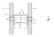
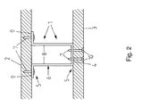
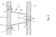
- the figures each show a connecting piece 1 for the spaced connection of two base plates 2, 3 of a lost formwork.
- the connecting piece 1 has two fastening regions 5 serving for fastening to the base plates 2, 3 and having contact surfaces 4 and a spacing region 6 extending between the fastening regions 5.
- the contact surfaces 4 are at least on one side from the side facing away from the distance region 6, i.e. through the base plates 2, 3 to be connected, by means of screws 7 on the base plates 2, 3.
- the connector 1 is a connector 1 with a double-walled spacing area 6.
- the walls 8 of the spacing area 6 and the fastening areas 5 are designed and arranged such that they together form a profile part with a rectangular cross-section in the sense form a rectangular shaped tube.
- the exemplary embodiment of a connecting piece according to the invention shown in FIG. 2 also has a double-walled spacing area 6.
- one of the fastening areas 5 is formed with two contact surfaces 9 serving to abut the base plate 1.
- These two contact surfaces 9 protrude outwards from the walls 8 of the spacing area 6 and are screwed directly to the base plate 2 from the inside by means of screws.
- the third exemplary embodiment of a connecting piece according to the invention finally shown in FIG. 3 is comparable to the exemplary embodiment shown in FIG. 2, the walls 8 of the double-walled spacing region 6 extending from one fastening region 5 to the opposite fastening region 5 in their Change relative position to each other, ie run approximately V-shaped. This creates a special connection stiffness or bending strength.
- FIGS 1 to 3 clearly show that in the selected embodiments of a lost formwork at least one of the two base plates 2, 3 is screwed from the outside.
- the base plates 2, 3 are designed as particle boards in the exemplary embodiments selected here.
- self-tapping screws 7 are used, which are only shown schematically in the figures.
- FIGs 1 to 3 also clearly show that the screws 7 screwed in from the outside are countersunk with their screw heads 10 in the base plate.
Landscapes
- Engineering & Computer Science (AREA)
- Architecture (AREA)
- Physics & Mathematics (AREA)
- Electromagnetism (AREA)
- Civil Engineering (AREA)
- Structural Engineering (AREA)
- Forms Removed On Construction Sites Or Auxiliary Members Thereof (AREA)
Applications Claiming Priority (2)
| Application Number | Priority Date | Filing Date | Title |
|---|---|---|---|
| DE4236958 | 1992-11-02 | ||
| DE19924236958 DE4236958A1 (de) | 1992-11-02 | 1992-11-02 | Verbindungsstück und eine verlorene Schalung |
Publications (1)
| Publication Number | Publication Date |
|---|---|
| EP0596451A1 true EP0596451A1 (fr) | 1994-05-11 |
Family
ID=6471907
Family Applications (1)
| Application Number | Title | Priority Date | Filing Date |
|---|---|---|---|
| EP93117730A Withdrawn EP0596451A1 (fr) | 1992-11-02 | 1993-11-02 | Connecteur et coffrage perdu |
Country Status (2)
| Country | Link |
|---|---|
| EP (1) | EP0596451A1 (fr) |
| DE (1) | DE4236958A1 (fr) |
Cited By (1)
| Publication number | Priority date | Publication date | Assignee | Title |
|---|---|---|---|---|
| EP0767280A1 (fr) * | 1995-10-06 | 1997-04-09 | KEWO Holding GmbH | Ecarteur pour coffrage à béton |
Families Citing this family (6)
| Publication number | Priority date | Publication date | Assignee | Title |
|---|---|---|---|---|
| DE19533539A1 (de) | 1995-09-11 | 1997-03-13 | Henkel Kgaa | O/W-Emulgatoren |
| DE19544710C2 (de) | 1995-11-30 | 1998-11-26 | Henkel Kgaa | Verdickungsmittel |
| DE19547986C1 (de) * | 1995-12-21 | 1997-07-10 | Henkel Kgaa | O/W-Mikroemulsionen |
| US5932535A (en) * | 1995-12-21 | 1999-08-03 | Henkel Kommanditgesellschaft Auf Aktien | Process for the production of light-colored, low-viscosity surfactant concentrates |
| DE19548068C1 (de) | 1995-12-21 | 1997-06-19 | Henkel Kgaa | Verfahren zur Herstellung hellfarbiger, niedrigviskoser Tensidkonzentrate |
| DE19625516A1 (de) * | 1996-06-26 | 1998-01-02 | Weberhaus Gmbh & Co Kg | Abstandhalter |
Citations (12)
| Publication number | Priority date | Publication date | Assignee | Title |
|---|---|---|---|---|
| BE657693A (fr) * | 1964-01-04 | |||
| FR632133A (fr) * | 1927-04-04 | 1928-01-04 | Construction de bâtiments en béton au moyen de plaques formant coffrages, et ensuite, revêtements par leur incorporation même dans la construction | |
| US3265217A (en) * | 1964-07-22 | 1966-08-09 | Angeles Metal Trim Co | Building construction |
| US3449877A (en) * | 1966-07-11 | 1969-06-17 | Miller Herman Inc | Space divider |
| DE1609464A1 (de) * | 1966-12-08 | 1970-06-11 | Reising Wolfgang | Bauelemente |
| DE1784998A1 (de) * | 1967-09-30 | 1972-07-06 | Tempes Geb Manthey | Abstandhalter fuer eine mantelbetonwand |
| US3841051A (en) * | 1972-05-30 | 1974-10-15 | D Zinn | Method of making walls |
| US4245442A (en) * | 1979-07-19 | 1981-01-20 | Durham I Milt | Reusable interior wall and ceiling construction system for buildings |
| DE3214502A1 (de) * | 1981-05-05 | 1982-12-02 | Franz Dipl.-Ing. Innsbruck Bucher | Plattenfoermiges bauelement fuer die mantelbetonbauweise |
| FR2562584A1 (fr) * | 1984-04-06 | 1985-10-11 | Sodeteg | Procede de fabrication de mur et mur obtenu par ce procede |
| DE3414388A1 (de) * | 1984-04-16 | 1985-12-12 | Peter Dipl.-Ing. 8910 Landsberg Wohlfahrt | Verlorene schalung fuer tragende gebaeudeteile aus beton, insbesondere fuer gebaeudedecken, ringanker und stuerze |
| US4651484A (en) * | 1986-03-31 | 1987-03-24 | National Gypsum Company | Furniture channel |
Family Cites Families (1)
| Publication number | Priority date | Publication date | Assignee | Title |
|---|---|---|---|---|
| AT385806B (de) * | 1986-07-03 | 1988-05-25 | Fuechtner Eva Maria Dipl Ing | Mindestens zweiteiliges verbindungsstueck zum zusammenhalten von zwei die fertige wand- bzw. deckenflaeche aufweisenden grundplatten |
-
1992
- 1992-11-02 DE DE19924236958 patent/DE4236958A1/de not_active Withdrawn
-
1993
- 1993-11-02 EP EP93117730A patent/EP0596451A1/fr not_active Withdrawn
Patent Citations (12)
| Publication number | Priority date | Publication date | Assignee | Title |
|---|---|---|---|---|
| FR632133A (fr) * | 1927-04-04 | 1928-01-04 | Construction de bâtiments en béton au moyen de plaques formant coffrages, et ensuite, revêtements par leur incorporation même dans la construction | |
| BE657693A (fr) * | 1964-01-04 | |||
| US3265217A (en) * | 1964-07-22 | 1966-08-09 | Angeles Metal Trim Co | Building construction |
| US3449877A (en) * | 1966-07-11 | 1969-06-17 | Miller Herman Inc | Space divider |
| DE1609464A1 (de) * | 1966-12-08 | 1970-06-11 | Reising Wolfgang | Bauelemente |
| DE1784998A1 (de) * | 1967-09-30 | 1972-07-06 | Tempes Geb Manthey | Abstandhalter fuer eine mantelbetonwand |
| US3841051A (en) * | 1972-05-30 | 1974-10-15 | D Zinn | Method of making walls |
| US4245442A (en) * | 1979-07-19 | 1981-01-20 | Durham I Milt | Reusable interior wall and ceiling construction system for buildings |
| DE3214502A1 (de) * | 1981-05-05 | 1982-12-02 | Franz Dipl.-Ing. Innsbruck Bucher | Plattenfoermiges bauelement fuer die mantelbetonbauweise |
| FR2562584A1 (fr) * | 1984-04-06 | 1985-10-11 | Sodeteg | Procede de fabrication de mur et mur obtenu par ce procede |
| DE3414388A1 (de) * | 1984-04-16 | 1985-12-12 | Peter Dipl.-Ing. 8910 Landsberg Wohlfahrt | Verlorene schalung fuer tragende gebaeudeteile aus beton, insbesondere fuer gebaeudedecken, ringanker und stuerze |
| US4651484A (en) * | 1986-03-31 | 1987-03-24 | National Gypsum Company | Furniture channel |
Cited By (1)
| Publication number | Priority date | Publication date | Assignee | Title |
|---|---|---|---|---|
| EP0767280A1 (fr) * | 1995-10-06 | 1997-04-09 | KEWO Holding GmbH | Ecarteur pour coffrage à béton |
Also Published As
| Publication number | Publication date |
|---|---|
| DE4236958A1 (de) | 1994-08-18 |
Similar Documents
| Publication | Publication Date | Title |
|---|---|---|
| EP0531869B1 (fr) | Pince de montage | |
| EP3540145B1 (fr) | Élément de revêtement et système de revêtement pour un mur | |
| EP2446096B1 (fr) | Support d`angle pour système de façade | |
| CH699766B1 (de) | Rahmenanschlussteil zur Befestigung an einem Rahmen. | |
| DD237529A5 (de) | Plattenfoermiges bauelement und baukonstruktion mit derartigen bauelementen | |
| DE202012008857U1 (de) | Vorwandmontagesystem | |
| EP0596451A1 (fr) | Connecteur et coffrage perdu | |
| DE202011100168U1 (de) | Befestigungswinkel für die Unterkonstruktion von vorgehängten Fassaden und Montagesystem umfassend wenigstens einen solchen Befestigungswinkel | |
| EP0430921A1 (fr) | Mur fait à partir de panneaux en forme de boîte | |
| EP3453807A1 (fr) | Dispositif de fixation pour éléments structurels en forme de plaque, en particulier éléments de façade | |
| DE29618158U1 (de) | Abstandhalter | |
| DE4000969A1 (de) | Anordnung zum befestigen einer gebaeudeplatte an einer gebaeudewand | |
| DE9214930U1 (de) | Verbindungsstück und eine verlorene Schalung | |
| DE29717135U1 (de) | Profilsystem für die Halterung von Verkleidungsplatten an Wänden oder Decken | |
| EP4229251A1 (fr) | Système de raccordement de panneau | |
| EP3216937A1 (fr) | Procédé de montage d'une construction à poteau-traverse et aide au montage | |
| DE102020127816A1 (de) | Verkleidungssystem für eine Wand und Anordnung des Verkleidungssystems an einer Wand | |
| DE202010014648U1 (de) | Befestigungsvorrichtung zur Befestigung eines Fassadenverkleidungselementes an einer Gebäudefassade | |
| DE19835106B4 (de) | Eckschutzschiene für Leichtbauplatten | |
| DE9214484U1 (de) | Vorrichtung zum abgewinkelten Verbinden vorzugsweise flächiger Teile | |
| DE102009016917B3 (de) | Montage-Hilfswerkzeug und Verfahren zur Montage von Bauplatten an eine Unterkonstruktion | |
| DE202026100854U1 (de) | Basissockelprofil | |
| DE102022115118A1 (de) | Tragprofilkonstruktion | |
| AT391163B (de) | Tuere | |
| EP0069798A1 (fr) | Elément de construction pour fixation de plaques de construction à poutres en acier |
Legal Events
| Date | Code | Title | Description |
|---|---|---|---|
| PUAI | Public reference made under article 153(3) epc to a published international application that has entered the european phase |
Free format text: ORIGINAL CODE: 0009012 |
|
| AK | Designated contracting states |
Kind code of ref document: A1 Designated state(s): AT BE CH DE DK ES FR GB GR IE IT LI LU MC NL PT SE |
|
| 17P | Request for examination filed |
Effective date: 19940726 |
|
| RBV | Designated contracting states (corrected) |
Designated state(s): AT BE CH FR LI LU |
|
| REG | Reference to a national code |
Ref country code: DE Ref legal event code: 8566 |
|
| 17Q | First examination report despatched |
Effective date: 19950807 |
|
| STAA | Information on the status of an ep patent application or granted ep patent |
Free format text: STATUS: THE APPLICATION HAS BEEN WITHDRAWN |
|
| 18W | Application withdrawn |
Withdrawal date: 19951205 |