EP0596800A1 - Verfahren und Vorrichtung zur katalytischen Dehydrierung einer C2+ paraffinischen Charge, einschliesslich eines Mittels zur Verwendung von Wasser im Ausfluss - Google Patents
Verfahren und Vorrichtung zur katalytischen Dehydrierung einer C2+ paraffinischen Charge, einschliesslich eines Mittels zur Verwendung von Wasser im Ausfluss Download PDFInfo
- Publication number
- EP0596800A1 EP0596800A1 EP93402700A EP93402700A EP0596800A1 EP 0596800 A1 EP0596800 A1 EP 0596800A1 EP 93402700 A EP93402700 A EP 93402700A EP 93402700 A EP93402700 A EP 93402700A EP 0596800 A1 EP0596800 A1 EP 0596800A1
- Authority
- EP
- European Patent Office
- Prior art keywords
- effluent
- water
- saturation
- solvent
- liquid phase
- Prior art date
- Legal status (The legal status is an assumption and is not a legal conclusion. Google has not performed a legal analysis and makes no representation as to the accuracy of the status listed.)
- Granted
Links
- XLYOFNOQVPJJNP-UHFFFAOYSA-N water Substances O XLYOFNOQVPJJNP-UHFFFAOYSA-N 0.000 title claims abstract description 112
- 238000006356 dehydrogenation reaction Methods 0.000 title claims abstract description 35
- 238000000034 method Methods 0.000 title claims abstract description 29
- 230000003197 catalytic effect Effects 0.000 title claims abstract description 11
- OKKJLVBELUTLKV-UHFFFAOYSA-N Methanol Chemical compound OC OKKJLVBELUTLKV-UHFFFAOYSA-N 0.000 claims abstract description 75
- 239000001257 hydrogen Substances 0.000 claims abstract description 42
- 229910052739 hydrogen Inorganic materials 0.000 claims abstract description 42
- 150000002430 hydrocarbons Chemical class 0.000 claims abstract description 36
- 239000002904 solvent Substances 0.000 claims abstract description 36
- 239000007791 liquid phase Substances 0.000 claims abstract description 35
- 229930195733 hydrocarbon Natural products 0.000 claims abstract description 34
- UFHFLCQGNIYNRP-UHFFFAOYSA-N Hydrogen Chemical compound [H][H] UFHFLCQGNIYNRP-UHFFFAOYSA-N 0.000 claims abstract description 33
- 229920006395 saturated elastomer Polymers 0.000 claims abstract description 23
- 239000004215 Carbon black (E152) Substances 0.000 claims abstract description 15
- 239000012071 phase Substances 0.000 claims description 27
- 230000006835 compression Effects 0.000 claims description 23
- 238000007906 compression Methods 0.000 claims description 23
- 238000005057 refrigeration Methods 0.000 claims description 23
- 238000000926 separation method Methods 0.000 claims description 22
- 238000001816 cooling Methods 0.000 claims description 17
- 239000007788 liquid Substances 0.000 claims description 16
- 238000004064 recycling Methods 0.000 claims description 13
- 239000008346 aqueous phase Substances 0.000 claims description 9
- 150000002431 hydrogen Chemical class 0.000 claims description 9
- 230000005764 inhibitory process Effects 0.000 claims description 9
- 239000000203 mixture Substances 0.000 claims description 9
- 239000007792 gaseous phase Substances 0.000 claims description 8
- 230000002401 inhibitory effect Effects 0.000 claims description 8
- 238000012856 packing Methods 0.000 claims description 7
- LFQSCWFLJHTTHZ-UHFFFAOYSA-N Ethanol Chemical compound CCO LFQSCWFLJHTTHZ-UHFFFAOYSA-N 0.000 claims description 6
- HEMHJVSKTPXQMS-UHFFFAOYSA-M Sodium hydroxide Chemical compound [OH-].[Na+] HEMHJVSKTPXQMS-UHFFFAOYSA-M 0.000 claims description 6
- 238000011084 recovery Methods 0.000 claims description 3
- NVJUHMXYKCUMQA-UHFFFAOYSA-N 1-ethoxypropane Chemical compound CCCOCC NVJUHMXYKCUMQA-UHFFFAOYSA-N 0.000 claims description 2
- XNWFRZJHXBZDAG-UHFFFAOYSA-N 2-METHOXYETHANOL Chemical compound COCCO XNWFRZJHXBZDAG-UHFFFAOYSA-N 0.000 claims description 2
- XTHFKEDIFFGKHM-UHFFFAOYSA-N Dimethoxyethane Chemical compound COCCOC XTHFKEDIFFGKHM-UHFFFAOYSA-N 0.000 claims description 2
- 150000008044 alkali metal hydroxides Chemical class 0.000 claims description 2
- 150000001875 compounds Chemical class 0.000 claims description 2
- NKDDWNXOKDWJAK-UHFFFAOYSA-N dimethoxymethane Chemical compound COCOC NKDDWNXOKDWJAK-UHFFFAOYSA-N 0.000 claims description 2
- POLCUAVZOMRGSN-UHFFFAOYSA-N dipropyl ether Chemical compound CCCOCCC POLCUAVZOMRGSN-UHFFFAOYSA-N 0.000 claims description 2
- 230000004907 flux Effects 0.000 claims description 2
- VNKYTQGIUYNRMY-UHFFFAOYSA-N methoxypropane Chemical compound CCCOC VNKYTQGIUYNRMY-UHFFFAOYSA-N 0.000 claims description 2
- 150000002894 organic compounds Chemical class 0.000 claims description 2
- BDERNNFJNOPAEC-UHFFFAOYSA-N propan-1-ol Chemical compound CCCO BDERNNFJNOPAEC-UHFFFAOYSA-N 0.000 claims description 2
- 239000012809 cooling fluid Substances 0.000 claims 1
- 238000004821 distillation Methods 0.000 claims 1
- 230000001105 regulatory effect Effects 0.000 claims 1
- BZLVMXJERCGZMT-UHFFFAOYSA-N Methyl tert-butyl ether Chemical compound COC(C)(C)C BZLVMXJERCGZMT-UHFFFAOYSA-N 0.000 abstract description 6
- 150000001336 alkenes Chemical class 0.000 abstract description 6
- 230000015572 biosynthetic process Effects 0.000 abstract description 3
- 238000003786 synthesis reaction Methods 0.000 abstract 1
- NNPPMTNAJDCUHE-UHFFFAOYSA-N isobutane Chemical compound CC(C)C NNPPMTNAJDCUHE-UHFFFAOYSA-N 0.000 description 28
- 239000001282 iso-butane Substances 0.000 description 14
- 238000006243 chemical reaction Methods 0.000 description 8
- 239000007789 gas Substances 0.000 description 7
- VQTUBCCKSQIDNK-UHFFFAOYSA-N Isobutene Chemical compound CC(C)=C VQTUBCCKSQIDNK-UHFFFAOYSA-N 0.000 description 6
- ATUOYWHBWRKTHZ-UHFFFAOYSA-N Propane Chemical compound CCC ATUOYWHBWRKTHZ-UHFFFAOYSA-N 0.000 description 6
- 238000010791 quenching Methods 0.000 description 6
- 230000000171 quenching effect Effects 0.000 description 5
- 238000011144 upstream manufacturing Methods 0.000 description 5
- 238000009835 boiling Methods 0.000 description 4
- 235000021183 entrée Nutrition 0.000 description 4
- 239000012535 impurity Substances 0.000 description 4
- 239000003507 refrigerant Substances 0.000 description 4
- 238000009834 vaporization Methods 0.000 description 4
- 230000008016 vaporization Effects 0.000 description 4
- 239000002808 molecular sieve Substances 0.000 description 3
- 239000001294 propane Substances 0.000 description 3
- URGAHOPLAPQHLN-UHFFFAOYSA-N sodium aluminosilicate Chemical compound [Na+].[Al+3].[O-][Si]([O-])=O.[O-][Si]([O-])=O URGAHOPLAPQHLN-UHFFFAOYSA-N 0.000 description 3
- 238000001179 sorption measurement Methods 0.000 description 3
- KAKZBPTYRLMSJV-UHFFFAOYSA-N Butadiene Chemical compound C=CC=C KAKZBPTYRLMSJV-UHFFFAOYSA-N 0.000 description 2
- 239000002585 base Substances 0.000 description 2
- 239000012530 fluid Substances 0.000 description 2
- VNWKTOKETHGBQD-UHFFFAOYSA-N methane Chemical compound C VNWKTOKETHGBQD-UHFFFAOYSA-N 0.000 description 2
- 238000009738 saturating Methods 0.000 description 2
- 230000006641 stabilisation Effects 0.000 description 2
- 238000011105 stabilization Methods 0.000 description 2
- 239000012808 vapor phase Substances 0.000 description 2
- 238000005406 washing Methods 0.000 description 2
- VXNZUUAINFGPBY-UHFFFAOYSA-N 1-Butene Chemical compound CCC=C VXNZUUAINFGPBY-UHFFFAOYSA-N 0.000 description 1
- CDBYLPFSWZWCQE-UHFFFAOYSA-L Sodium Carbonate Chemical compound [Na+].[Na+].[O-]C([O-])=O CDBYLPFSWZWCQE-UHFFFAOYSA-L 0.000 description 1
- 239000000654 additive Substances 0.000 description 1
- 230000000996 additive effect Effects 0.000 description 1
- QVGXLLKOCUKJST-UHFFFAOYSA-N atomic oxygen Chemical compound [O] QVGXLLKOCUKJST-UHFFFAOYSA-N 0.000 description 1
- 239000001273 butane Substances 0.000 description 1
- IAQRGUVFOMOMEM-UHFFFAOYSA-N butene Natural products CC=CC IAQRGUVFOMOMEM-UHFFFAOYSA-N 0.000 description 1
- 125000004432 carbon atom Chemical group C* 0.000 description 1
- 239000003054 catalyst Substances 0.000 description 1
- 238000006555 catalytic reaction Methods 0.000 description 1
- 239000000571 coke Substances 0.000 description 1
- 238000009833 condensation Methods 0.000 description 1
- 230000005494 condensation Effects 0.000 description 1
- 239000002826 coolant Substances 0.000 description 1
- 238000010908 decantation Methods 0.000 description 1
- 239000000428 dust Substances 0.000 description 1
- 238000007710 freezing Methods 0.000 description 1
- 230000008014 freezing Effects 0.000 description 1
- 239000000446 fuel Substances 0.000 description 1
- 239000002737 fuel gas Substances 0.000 description 1
- 239000000295 fuel oil Substances 0.000 description 1
- 239000008246 gaseous mixture Substances 0.000 description 1
- 150000004677 hydrates Chemical class 0.000 description 1
- 239000000543 intermediate Substances 0.000 description 1
- 239000003350 kerosene Substances 0.000 description 1
- 208000003173 lipoprotein glomerulopathy Diseases 0.000 description 1
- 238000004519 manufacturing process Methods 0.000 description 1
- 238000005259 measurement Methods 0.000 description 1
- GBMDVOWEEQVZKZ-UHFFFAOYSA-N methanol;hydrate Chemical compound O.OC GBMDVOWEEQVZKZ-UHFFFAOYSA-N 0.000 description 1
- 238000002156 mixing Methods 0.000 description 1
- 150000005673 monoalkenes Chemical class 0.000 description 1
- IJDNQMDRQITEOD-UHFFFAOYSA-N n-butane Chemical compound CCCC IJDNQMDRQITEOD-UHFFFAOYSA-N 0.000 description 1
- OFBQJSOFQDEBGM-UHFFFAOYSA-N n-pentane Natural products CCCCC OFBQJSOFQDEBGM-UHFFFAOYSA-N 0.000 description 1
- -1 natural gas Chemical class 0.000 description 1
- 239000003345 natural gas Substances 0.000 description 1
- TVMXDCGIABBOFY-UHFFFAOYSA-N octane Chemical compound CCCCCCCC TVMXDCGIABBOFY-UHFFFAOYSA-N 0.000 description 1
- 238000005839 oxidative dehydrogenation reaction Methods 0.000 description 1
- 239000001301 oxygen Substances 0.000 description 1
- 229910052760 oxygen Inorganic materials 0.000 description 1
- 230000008929 regeneration Effects 0.000 description 1
- 238000011069 regeneration method Methods 0.000 description 1
Images

Classifications
-
- C—CHEMISTRY; METALLURGY
- C07—ORGANIC CHEMISTRY
- C07C—ACYCLIC OR CARBOCYCLIC COMPOUNDS
- C07C11/00—Aliphatic unsaturated hydrocarbons
- C07C11/02—Alkenes
-
- B—PERFORMING OPERATIONS; TRANSPORTING
- B01—PHYSICAL OR CHEMICAL PROCESSES OR APPARATUS IN GENERAL
- B01J—CHEMICAL OR PHYSICAL PROCESSES, e.g. CATALYSIS OR COLLOID CHEMISTRY; THEIR RELEVANT APPARATUS
- B01J8/00—Chemical or physical processes in general, conducted in the presence of fluids and solid particles; Apparatus for such processes
- B01J8/02—Chemical or physical processes in general, conducted in the presence of fluids and solid particles; Apparatus for such processes with stationary particles, e.g. in fixed beds
- B01J8/0285—Heating or cooling the reactor
-
- C—CHEMISTRY; METALLURGY
- C07—ORGANIC CHEMISTRY
- C07C—ACYCLIC OR CARBOCYCLIC COMPOUNDS
- C07C5/00—Preparation of hydrocarbons from hydrocarbons containing the same number of carbon atoms
- C07C5/32—Preparation of hydrocarbons from hydrocarbons containing the same number of carbon atoms by dehydrogenation with formation of free hydrogen
- C07C5/327—Formation of non-aromatic carbon-to-carbon double bonds only
- C07C5/333—Catalytic processes
-
- C—CHEMISTRY; METALLURGY
- C07—ORGANIC CHEMISTRY
- C07C—ACYCLIC OR CARBOCYCLIC COMPOUNDS
- C07C7/00—Purification; Separation; Use of additives
- C07C7/11—Purification; Separation; Use of additives by absorption, i.e. purification or separation of gaseous hydrocarbons with the aid of liquids
-
- B—PERFORMING OPERATIONS; TRANSPORTING
- B01—PHYSICAL OR CHEMICAL PROCESSES OR APPARATUS IN GENERAL
- B01J—CHEMICAL OR PHYSICAL PROCESSES, e.g. CATALYSIS OR COLLOID CHEMISTRY; THEIR RELEVANT APPARATUS
- B01J2208/00—Processes carried out in the presence of solid particles; Reactors therefor
- B01J2208/00008—Controlling the process
- B01J2208/00017—Controlling the temperature
- B01J2208/00106—Controlling the temperature by indirect heat exchange
- B01J2208/00168—Controlling the temperature by indirect heat exchange with heat exchange elements outside the bed of solid particles
- B01J2208/00212—Plates; Jackets; Cylinders
-
- B—PERFORMING OPERATIONS; TRANSPORTING
- B01—PHYSICAL OR CHEMICAL PROCESSES OR APPARATUS IN GENERAL
- B01J—CHEMICAL OR PHYSICAL PROCESSES, e.g. CATALYSIS OR COLLOID CHEMISTRY; THEIR RELEVANT APPARATUS
- B01J2208/00—Processes carried out in the presence of solid particles; Reactors therefor
- B01J2208/00008—Controlling the process
- B01J2208/00017—Controlling the temperature
- B01J2208/00106—Controlling the temperature by indirect heat exchange
- B01J2208/00168—Controlling the temperature by indirect heat exchange with heat exchange elements outside the bed of solid particles
- B01J2208/00256—Controlling the temperature by indirect heat exchange with heat exchange elements outside the bed of solid particles in a heat exchanger for the heat exchange medium separate from the reactor
-
- B—PERFORMING OPERATIONS; TRANSPORTING
- B01—PHYSICAL OR CHEMICAL PROCESSES OR APPARATUS IN GENERAL
- B01J—CHEMICAL OR PHYSICAL PROCESSES, e.g. CATALYSIS OR COLLOID CHEMISTRY; THEIR RELEVANT APPARATUS
- B01J2219/00—Chemical, physical or physico-chemical processes in general; Their relevant apparatus
- B01J2219/00002—Chemical plants
- B01J2219/00004—Scale aspects
- B01J2219/00006—Large-scale industrial plants
-
- Y—GENERAL TAGGING OF NEW TECHNOLOGICAL DEVELOPMENTS; GENERAL TAGGING OF CROSS-SECTIONAL TECHNOLOGIES SPANNING OVER SEVERAL SECTIONS OF THE IPC; TECHNICAL SUBJECTS COVERED BY FORMER USPC CROSS-REFERENCE ART COLLECTIONS [XRACs] AND DIGESTS
- Y02—TECHNOLOGIES OR APPLICATIONS FOR MITIGATION OR ADAPTATION AGAINST CLIMATE CHANGE
- Y02P—CLIMATE CHANGE MITIGATION TECHNOLOGIES IN THE PRODUCTION OR PROCESSING OF GOODS
- Y02P20/00—Technologies relating to chemical industry
- Y02P20/10—Process efficiency
- Y02P20/129—Energy recovery, e.g. by cogeneration, H2recovery or pressure recovery turbines
Definitions
- the invention relates to a process for catalytic dehydrogenation of a C2 + paraffinic hydrocarbon feedstock and to a device for carrying out the process. It relates more specifically to the inhibition of the water contained in the effluent before refrigeration and the separation of the effluent.
- Patent EP-A-7750 describes a process for removing the water contained in light non-olefinic hydrocarbons such as natural gas, liquefied gases, gasolines or kerosene, by adding aqueous methanol. Under these conditions, a liquid hydrocarbon phase containing methanol is obtained which prevents the formation of hydrates. In addition, methanol is not recovered from the aqueous liquid phase.
- the recycled hydrogen and the hydrogen produced ensure a partial pressure of hydrogen sufficient to inhibit the formation of coke and thereby maintain the stability of the catalyst. This achieves satisfactory conversion at a higher temperature range, for example around 600 ° C.
- the low pressure effluent delivered by the dehydrogenation reaction zone is cooled first by heat exchange with the gaseous charge and then with water, to a suitable temperature before the vapor pressure of the effluent is not effectively reassembled in conventional compression equipment, at a higher pressure, which allows the separation of hydrogen and hydrocarbon compounds from the effluent.
- These traditional exchangers and other air coolers increase the back pressure of the reaction system, which negatively affects the conversion rate.
- attempts have been made to use heat exchangers with low pressure drop and direct cooling with circulating (quenching) coolants, but without great success.
- the separation of hydrogen from the effluent hydrocarbons must be carried out at a pressure higher than that prevailing in the reaction zone.
- molecular sieve adsorption beds also impose pressure losses on the compression effluent due not only to the adsorption beds themselves but to the filter systems downstream of these beds which capture the molecular sieve dust. likely to obstruct the flow of effluent through refrigeration equipment.
- the sieves molecular involve periods of water adsorption followed by periods of regeneration which are difficult to control.
- An object of the invention is to remedy the drawbacks mentioned above.
- the invention therefore relates to a process for catalytic dehydrogenation of a C par + paraffinic hydrocarbon charge comprising a step of dehydrogenation of said charge in the gas phase, optionally in the presence of hydrogen, delivering a gaseous dehydrogenation effluent comprising water, hydrogen, olefinic hydrocarbons and unconverted paraffinic hydrocarbons, at least one step of cooling the effluent, a step of compressing the cooled effluent to an appropriate pressure, a step of inhibiting the water contained in the compressed effluent, a stage of refrigeration in a heat exchanger of the compressed effluent, a stage of separation of the compressed effluent and refrigerated in a separation zone under suitable conditions and a stage of recovery of hydrogen and d '' mainly olefinic hydrocarbons.
- the cooled effluent can be effectively saturated by introducing into the upper part of the saturation zone the aqueous liquid phase recovered from the stripping column and a recycled aqueous phase recovered at the bottom of the saturation zone , by introducing the cooled effluent into the lower part of the saturation zone, by making direct contact against the flow of the effluent with the mixture of aqueous phases through an appropriate packing, by recovering the aqueous phase at the bottom of the the saturation zone that we recycle, after having cooled it at least once, at the upper part of said zone, and the effluent saturated with water and cooled is recovered in the upper part of the saturation zone.
- the mixture of aqueous phases introduced into the saturation zone is at a temperature of -10 to + 90 ° C. It can advantageously contain from 1 to 15% of an alkali metal hydroxide and preferably sodium hydroxide.
- the temperature of the saturation column is generally from 0 to 100 ° C and advantageously from 20 to 50 ° C.
- This column is usually operated under a pressure which can range from atmospheric pressure to 3 bar absolute and more particularly from atmospheric pressure to 1.5 bar absolute, when the column for saturating the effluent with water is placed between the dehydrogenation reactor and effluent compression equipment.
- the saturation column can operate under a pressure of 3 to 35 bar absolute and preferably 8 to 15 bar absolute.
- the stripping of the solvent in the stripping column is generally carried out at a temperature of 10 to 150 ° C, preferably 80 to 120 ° C under a pressure of 3 to 35 bar absolute and preferably 10 to 15 bar absolute.
- the effluent refrigeration step carried out by an auto-refrigeration device (vaporization of the liquid charge with or without recycled hydrogen) or by an external refrigeration device, can be carried out at a temperature of 0 to -85 ° C. , preferably -20 to -40 ° C under a pressure of 3 to 35 bar absolute.
- the separation of the effluent into hydrogen, olefins and the liquid phase water and methanol which is decanted is generally carried out at 3 to 35 bar absolute, preferably under 8 to 12 bar absolute and at a temperature of 0 to - 100 ° C and more particularly from -20 to -40 ° C.
- This stripping column usually comprises a preferably structured packing, of height equivalent to at least 1 theoretical plate, for example 1 to 20 and advantageously 10 to 15 plates.
- the concentration of methanol in the decanted water-methanol phase coming from the step of refrigerating the effluent which is introduced into the stripping column is generally 20 to 80% by weight, and preferably 50-65%.
- the density of the solvent in the water constituting the decanted phase is measured, which allows its concentration to be obtained and by comparison with a reference value stored in a microcomputer, this concentration can be adjusted to the level desired by l 'addition of a solvent-containing flux to the compressed effluent.
- This flow can advantageously be the solvent or the washing water (methanol) of a downstream unit for producing methyl tert-butyl ether.
- the solvent used must be at least partially miscible with water. Preferably, it must have a boiling temperature lower than that of water or form with water an azeotrope whose boiling temperature is lower than that of water, so that it can be entrained by the phase. gas constituting the effluent during the contacting step of the process. It must also be sparingly soluble in hydrocarbons.
- This solvent can advantageously be methanol and ethanol and preferably methanol because of its low cost. It can also be chosen for example from the following solvents: methylpropylether, ethylpropylether, dipropylether, methyltertiobutylether, dimethoxymethane, dimethoxyethane, ethanol, methoxyethanol, propanol.
- the invention also relates to the catalytic dehydrogenation unit comprising in combination a dehydrogenation reactor (40) delivering an effluent containing water, means (12, 2) for supplying a hydrocarbon feedstock connected to an inlet to the reactor. , at least one means (41) for cooling an effluent connected to an outlet of the reactor, means (6) for compressing the effluent, means for inhibiting the water contained in the effluent, means refrigeration (13) of the compressed effluent connected to the water inhibition means, separation means (8) of the refrigerated effluent connected to the refrigeration means, recovery means (22, 18) of a phase rich in hydrogen and a liquid phase containing olefinic hydrocarbons,
- the first inlet of the saturation enclosure is connected to said means (41) for cooling the effluent
- the second outlet of the saturation enclosure is connected to an inlet of the compression means (6)
- the first inlet of the water saturated effluent in the stripping column (10) is connected to an outlet (7) of the compression means.
- outlet of the compression means can also be connected to the effluent refrigeration means when all of the effluent does not pass through the stripping column.
- the means for cooling the effluent at the outlet of the reactor can be connected to an inlet of the compression means, the first inlet of the saturation enclosure (3) is connected to an outlet of the compression means (6) and the second outlet of the saturation chamber (3) is directly connected to the first inlet of the stripping column (10).
- the second outlet of the saturation enclosure can also be connected to the refrigeration means when all of the effluent does not pass through the stripping column.
- the charge can comprise paraffinic hydrocarbons with 3, 4 and / or 5 carbon atoms. More particularly, it can comprise isobutane.
- It can be introduced in liquid form or in gaseous form, with or without the presence of recycled hydrogen.
- the present invention has the advantage of requiring pressure levels, both in the dehydrogenation reactor and in the compression devices, which are much lower due to the low losses of load due to water saturation devices and therefore direct quenching of the effluent, and inhibition of water by the use of solvents.
- the devices for cooling the effluent with a view to its separation into gas (hydrogen) and liquid (olefins and unconverted paraffinic hydrocarbons) can be external (indirect exchange with propane for example).
- they can comprise a heat exchanger with double enclosure, the first of which is supplied by the liquid charge without or with at least part of the recycled hydrogen coming from the separation means, this hydrogen being able moreover be relaxed before entering the first enclosure of the heat exchanger.
- the vaporization of the charge with or without hydrogen then contributes to the cooling of the effluent in the second enclosure of the heat exchanger (tubes or plates for example).
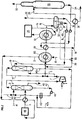
- FIGS. 1 and 2 schematically illustrating the method and the device according to the invention among which:
- FIG. 1 represents a dehydrogenation unit of a section containing 93% isobutane comprising the water inhibition device according to the invention and an effluent auto-cooling system.
- Figure 2 shows a dehydrogenation unit comprising the water inhibition device according to the invention and an external cooling system for the effluent.
- the effluent 1 which leaves it enriched with olefinic hydrocarbons (more than 50% by example) is cooled by indirect exchange in this plate exchanger, then in another exchanger 3 which is a structured packed column with a large specific surface area and a height equivalent to about 5 theoretical plates. This column performs a direct quenching of the effluent at a temperature of about 20 to 50 ° C, saturates the effluent with water and rids it of its impurities.
- the effluent is introduced into the column through its lower part, passes through the packing from bottom to top where it is brought into counter-current contact with a mixture of liquid phases containing water introduced into the upper part of the column, partly from a recycling line 42 at the base of column 3 via a pump 45 and at least one air exchanger 43 and for the remaining part from a stripping column 10 from a supply line 42a.
- Soda (approximately 5% by weight) can be introduced via a line 44 into line 42 to wash the effluent from its undesirable impurities.
- Water can be drawn from the lower part of the quench and saturation column by a line 46.
- the effluent cooled to about 20-50 ° C but still overheated is collected at the top of the column and fed by a line 5 the suction of a centrifugal compression system 6, at a pressure substantially higher than atmospheric pressure.
- the compression system 6 raises the pressure of the reaction effluent to a value such that effective separation of a liquid hydrocarbon phase from a gaseous phase rich in hydrogen becomes possible at a temperature generally below 0 ° C. In the case of the dehydrogenation of isobutane, a pressure of 13 to 18 bar is entirely appropriate.
- the energy requirements of the compression system can be supplied by a gas turbine, a steam turbine or an electric motor.
- a line 7 divides the compressed and water-saturated effluent into two streams.
- a first flow representing 5 to 10% of the effluent is directed by a line 11 towards the lower part of a column 10 for inhibiting water (or stripping) containing a structured packing, for example a SULZER BX packing having 5 to 10 equivalent theoretical platforms.
- an aqueous phase is recovered containing substantially no more solvent, which is recycled to the upper inlet of the saturation column 3.
- a line 47 discharges a phase gaseous charged with solvent and hydrocarbon effluent to the remaining part of the compressed effluent, saturated with water and cooled by an air or water heat exchanger 51 and the effluent-methanol-water mixture is cooled by an indirect heat exchange in an exchanger 19 with an effluent 18 from a separation enclosure 8 containing the olefinic hydrocarbons (more than 50% for example) and unconverted saturated.
- this mixture the water present of which is inhibited by the presence of methanol in an adequate quantity, is introduced into a heat exchanger 13 with tubes and a calender adapted to refrigerate the effluent by indirect exchange.
- the charge of fresh and unconverted isobutane liquid, therefore recycled, is brought by a line 12 in the liquid phase and cooled in a heat exchanger 28 at the base of the shell of the heat exchanger 13.
- the presence of water in the load can be inhibited by adding methanol 12a to line 12.
- This liquid phase is vaporized by the heat given off by the tubes in the presence of at least part of recycled hydrogen introduced through a line 15 into the shell, which contributes to lower its boiling point to a given pressure.
- the hydrogen is introduced into the lower part of the calender by means 61 adapted to promote contact with said liquid phase substantially throughout the volume occupied by it. In these conditions, it is used as a refrigerant.
- a gaseous phase is recovered in the upper part of the shell, comprising the vaporized isobutane and the recycled hydrogen and evacuated by a line 2 in the direction of the plate heat exchanger 41 upstream of the reactor 40 so as to cool the 'effluent.
- a condensate of methanol and water can be recovered in the lower part 13a of the shell which can be recycled by a line 50 to the supply 9 of the stripping column 10.
- the pressure inside the shell of the heat exchanger 13 adapted to refrigerate the effluent and therefore the vaporization pressure is maintained at a appropriate level by a variable speed single stage compressor 14 which has its input connected directly to the grille.
- the pressure in the calender is maintained at approximately 2 bar absolute.
- the charge in the vapor phase isobutane and hydrogen
- the inlet of the dehydrogenation reactor at a pressure of 3 to 4 bar absolute.
- the refrigerated effluent in the tubes of the heat exchanger 13 leaves via a line 16 at a temperature of about -20 to -25 ° C for example and is directed to a phase separator 8.
- a line 22 recovers a vapor phase containing mainly hydrogen and a small proportion of hydrocarbons and leads it to a turboexpander 23 where it is expanded at constant entropy of a pressure, for example of 15 bar at a pressure of approximately 2.5 bar.
- the temperature in line 26 typically drops, from about -25 ° C to -85 ° C, which causes the condensation of a so-called cryogenic hydrocarbon liquid phase which is separated from the hydrogen in a separation enclosure 27.
- This liquid phase is recovered at the bottom of the enclosure 27 by a line 17 and mixed with the refrigerated effluent leaving the refrigerant heat exchanger 13, at a point upstream of the inlet of the separator 8
- This direct contact by appropriate mixing means contributes to cooling the compressed effluent by an additional 2 to 10 ° C.
- a gaseous hydrogen phase is recovered (more than 98 mol% of hydrogen) which is divided to form a stream of hydrogen intended to be recycled in part by a line 15 and first sent to the shell of the refrigerant heat exchanger 13 to vaporize the liquid charge of isobutane.
- the other part of the hydrogen stream is directed by a line 25 to a compressor 24 set in motion by the turboexpander 23.
- This stream of hydrogen compressed to about 10 bar and at a temperature of -30 ° C can be heated in a heat exchanger 28 disposed on line 12 in downstream from the addition 12a of methanol, by indirect exchange with the liquid charge of isobutane, and can therefore contribute to cooling the charge before its vaporization.
- a liquid hydrocarbon phase is recovered via a line 18 at approximately -25 ° C. and approximately 15 bar absolute, comprising at least 95% of isobutene contained in the effluent, which cools in a 19 l heat exchanger hydrocarbon effluent before entering the refrigerant heat exchanger 13.
- the liquid hydrocarbon phase is again reheated in another heat exchanger 21 before being introduced into a stabilization column 20 delivering fuel oil at the head via a line 33 and at the bottom by a line 34 of isobutene and unconverted isobutane which contribute to the heat exchange in the exchanger 21 and which is sent to an MTBE training unit (not shown).
- a liquid phase decanted with water containing 20 to 70% by weight of methanol is recovered, which is recycled by a line 9 and a pump 49 to the upper inlet of the stripping column.
- the methanol concentration to be introduced into the hydrocarbon effluent to be refrigerated can be continuously monitored by a hydrometer 31 immersed in the decantation chamber 30 of the separator 8 which allows density and then concentration measurements.
- the hydrometer is connected to a microcomputer 32 which controls, by comparison with a range of previously recorded concentrations, an opening or closing valve 60 of a supply line 36 in a fluid containing methanol, to line 47.
- FIG 2 which illustrates a variant of the catalytic dehydrogenation unit of an isobutane cut
- the device for saturation and inhibition of water with methanol is identical to that shown in Figure 1 with the same references.
- the charge of liquid isobutane is introduced via line 12 into a heat exchanger 60 where it is vaporized in the absence of hydrogen by indirect exchange with the effluent. hydrocarbon coming from the dehydrogenation reactor and containing the adequate proportion of methanol according to the invention.
- the effluent is further cooled in the heat exchanger 19 by indirect exchange with olefins and unconverted hydrocarbons coming from the separator 8 via line 18 and is then refrigerated between -20 and -40 ° C in an indirect heat exchanger 13 by a device 35 for external refrigeration, for example with propane, before being conveyed in the separator 8 by line 16.
- the hydrogen is recovered at the head by line 22 while the olefins and fuel gas are recovered by line 18 to be separated in the stabilization column 20.
- the decanted phase in the lower enclosure 30 of the separator 8 containing the liquid water and methanol phase is recycled as described above by line 9 to the stripping column 10.
Landscapes
- Chemical & Material Sciences (AREA)
- Organic Chemistry (AREA)
- Chemical Kinetics & Catalysis (AREA)
- Engineering & Computer Science (AREA)
- Analytical Chemistry (AREA)
- Oil, Petroleum & Natural Gas (AREA)
- Water Supply & Treatment (AREA)
- Organic Low-Molecular-Weight Compounds And Preparation Thereof (AREA)
Applications Claiming Priority (2)
| Application Number | Priority Date | Filing Date | Title |
|---|---|---|---|
| FR9213516A FR2697835B1 (fr) | 1992-11-06 | 1992-11-06 | Procédé et dispositif de déshydrogénation catalytique d'une charge paraffinique C2+ comprenant des moyens pour inhiber l'eau dans l'effluent. |
| FR9213516 | 1992-11-06 |
Publications (2)
| Publication Number | Publication Date |
|---|---|
| EP0596800A1 true EP0596800A1 (de) | 1994-05-11 |
| EP0596800B1 EP0596800B1 (de) | 1997-03-12 |
Family
ID=9435398
Family Applications (1)
| Application Number | Title | Priority Date | Filing Date |
|---|---|---|---|
| EP93402700A Expired - Lifetime EP0596800B1 (de) | 1992-11-06 | 1993-11-03 | Verfahren und Vorrichtung zur katalytischen Dehydrierung einer C2+ paraffinischen Charge, einschliesslich eines Mittels zur Hemmung von Wasser im Ausfluss |
Country Status (8)
| Country | Link |
|---|---|
| US (2) | US5489725A (de) |
| EP (1) | EP0596800B1 (de) |
| JP (1) | JPH06219969A (de) |
| CA (1) | CA2102557A1 (de) |
| DE (1) | DE69308738T2 (de) |
| ES (1) | ES2101977T3 (de) |
| FR (1) | FR2697835B1 (de) |
| NO (1) | NO305941B1 (de) |
Cited By (1)
| Publication number | Priority date | Publication date | Assignee | Title |
|---|---|---|---|---|
| US5491274A (en) * | 1992-11-06 | 1996-02-13 | Institut Francais Du Petrole | Process and device for catalytic dehydrogenation of a c2+ paraffinic charge comprising a self-cooling system |
Families Citing this family (53)
| Publication number | Priority date | Publication date | Assignee | Title |
|---|---|---|---|---|
| US7019339B2 (en) * | 2001-04-17 | 2006-03-28 | California Institute Of Technology | Method of using a germanium layer transfer to Si for photovoltaic applications and heterostructure made thereby |
| US7238622B2 (en) * | 2001-04-17 | 2007-07-03 | California Institute Of Technology | Wafer bonded virtual substrate and method for forming the same |
| US20050026432A1 (en) * | 2001-04-17 | 2005-02-03 | Atwater Harry A. | Wafer bonded epitaxial templates for silicon heterostructures |
| US7591150B2 (en) * | 2001-05-04 | 2009-09-22 | Battelle Energy Alliance, Llc | Apparatus for the liquefaction of natural gas and methods relating to same |
| US7594414B2 (en) * | 2001-05-04 | 2009-09-29 | Battelle Energy Alliance, Llc | Apparatus for the liquefaction of natural gas and methods relating to same |
| US20070137246A1 (en) * | 2001-05-04 | 2007-06-21 | Battelle Energy Alliance, Llc | Systems and methods for delivering hydrogen and separation of hydrogen from a carrier medium |
| US7219512B1 (en) * | 2001-05-04 | 2007-05-22 | Battelle Energy Alliance, Llc | Apparatus for the liquefaction of natural gas and methods relating to same |
| US7637122B2 (en) | 2001-05-04 | 2009-12-29 | Battelle Energy Alliance, Llc | Apparatus for the liquefaction of a gas and methods relating to same |
| US6838587B2 (en) | 2002-04-19 | 2005-01-04 | Exxonmobil Chemical Patents Inc. | Method of removing oxygenate contaminants from an olefin stream |
| US7060866B2 (en) * | 2002-04-18 | 2006-06-13 | Exxonmobil Chemical Patents Inc. | High pressure separation of dimethyl ether from an olefin stream |
| US20030199721A1 (en) * | 2002-04-18 | 2003-10-23 | Ding Zhong Y. | Low pressure separation of dimethyl ether from an olefin stream |
| US7030284B2 (en) * | 2002-08-20 | 2006-04-18 | Exxonmobil Chemical Patents Inc. | Method and reactor system for converting oxygenate contaminants in an MTO reactor system product effluent to hydrocarbons |
| WO2005104192A2 (en) * | 2004-04-21 | 2005-11-03 | California Institute Of Technology | A METHOD FOR THE FABRICATION OF GaAs/Si AND RELATED WAFER BONDED VIRTUAL SUBSTRATES |
| WO2006015185A2 (en) * | 2004-07-30 | 2006-02-09 | Aonex Technologies, Inc. | GaInP/GaAs/Si TRIPLE JUNCTION SOLAR CELL ENABLED BY WAFER BONDING AND LAYER TRANSFER |
| US7846759B2 (en) * | 2004-10-21 | 2010-12-07 | Aonex Technologies, Inc. | Multi-junction solar cells and methods of making same using layer transfer and bonding techniques |
| US10374120B2 (en) * | 2005-02-18 | 2019-08-06 | Koninklijke Philips N.V. | High efficiency solar cells utilizing wafer bonding and layer transfer to integrate non-lattice matched materials |
| WO2006116030A2 (en) * | 2005-04-21 | 2006-11-02 | Aonex Technologies, Inc. | Bonded intermediate substrate and method of making same |
| US20070243703A1 (en) * | 2006-04-14 | 2007-10-18 | Aonex Technololgies, Inc. | Processes and structures for epitaxial growth on laminate substrates |
| US20100018248A1 (en) * | 2007-01-19 | 2010-01-28 | Eleanor R Fieler | Controlled Freeze Zone Tower |
| CA2674618C (en) * | 2007-01-19 | 2015-02-10 | Exxonmobil Upstream Research Company | Integrated controlled freeze zone (cfz) tower and dividing wall (dwc) for enhanced hydrocarbon recovery |
| US7732301B1 (en) | 2007-04-20 | 2010-06-08 | Pinnington Thomas Henry | Bonded intermediate substrate and method of making same |
| US20090278233A1 (en) * | 2007-07-26 | 2009-11-12 | Pinnington Thomas Henry | Bonded intermediate substrate and method of making same |
| US9217603B2 (en) | 2007-09-13 | 2015-12-22 | Battelle Energy Alliance, Llc | Heat exchanger and related methods |
| US9254448B2 (en) | 2007-09-13 | 2016-02-09 | Battelle Energy Alliance, Llc | Sublimation systems and associated methods |
| US8555672B2 (en) * | 2009-10-22 | 2013-10-15 | Battelle Energy Alliance, Llc | Complete liquefaction methods and apparatus |
| US9574713B2 (en) | 2007-09-13 | 2017-02-21 | Battelle Energy Alliance, Llc | Vaporization chambers and associated methods |
| US8899074B2 (en) | 2009-10-22 | 2014-12-02 | Battelle Energy Alliance, Llc | Methods of natural gas liquefaction and natural gas liquefaction plants utilizing multiple and varying gas streams |
| US8061413B2 (en) | 2007-09-13 | 2011-11-22 | Battelle Energy Alliance, Llc | Heat exchangers comprising at least one porous member positioned within a casing |
| US8013201B2 (en) * | 2008-07-30 | 2011-09-06 | Lummus Technology Inc. | High energy reduction in a propane dehydrogenation unit by utilizing a high pressure product splitter column |
| MY155414A (en) | 2009-04-20 | 2015-10-15 | Exxonmobil Upstream Res Co | Cryogenic system for removing acid gases from a hydrocarbon gas stream, and method of removing acid gases |
| MY161120A (en) | 2009-09-09 | 2017-04-14 | Exxonmobil Upstream Res Co | Cryogenic system for removing acid gases from a hydrocarbon gas stream |
| BR112012017599A2 (pt) | 2010-01-22 | 2016-08-16 | Exxonmobil Upstream Res Co | remoção de gases ácidos de um fluxo de gás, com captura e sequestro de co2 |
| SG182399A1 (en) | 2010-02-03 | 2012-08-30 | Exxonmobil Upstream Res Co | Systems and methods for using cold liquid to remove solidifiable gas components from process gas streams |
| MX362706B (es) | 2010-07-30 | 2019-02-01 | Exxonmobil Upstream Res Company Star | Sistemas criogenicos para remover gases acidos de una corriente de gas de hidrocarburo que usan dispositivos de separacion de co-corriente. |
| CA2867287C (en) | 2012-03-21 | 2019-06-11 | Exxonmobil Upstream Research Company | Separating carbon dioxide and ethane from a mixed stream |
| US10655911B2 (en) | 2012-06-20 | 2020-05-19 | Battelle Energy Alliance, Llc | Natural gas liquefaction employing independent refrigerant path |
| WO2015084494A2 (en) | 2013-12-06 | 2015-06-11 | Exxonmobil Upstream Research Company | Method and device for separating hydrocarbons and contaminants with a spray assembly |
| MY176633A (en) | 2013-12-06 | 2020-08-19 | Exxonmobil Upstream Res Co | Method and system of modifiying a liquid level during start-up operations |
| US10139158B2 (en) | 2013-12-06 | 2018-11-27 | Exxonmobil Upstream Research Company | Method and system for separating a feed stream with a feed stream distribution mechanism |
| WO2015084497A2 (en) | 2013-12-06 | 2015-06-11 | Exxonmobil Upstream Research Company | Method and system of dehydrating a feed stream processed in a distillation tower |
| US9829247B2 (en) | 2013-12-06 | 2017-11-28 | Exxonmobil Upstream Reseach Company | Method and device for separating a feed stream using radiation detectors |
| MY177768A (en) | 2013-12-06 | 2020-09-23 | Exxonmobil Upstream Res Co | Method and device for separating hydrocarbons and contaminants with a heating mechanism to destabilize and/or prevent adhesion of solids |
| US9874395B2 (en) | 2013-12-06 | 2018-01-23 | Exxonmobil Upstream Research Company | Method and system for preventing accumulation of solids in a distillation tower |
| WO2015084495A2 (en) | 2013-12-06 | 2015-06-11 | Exxonmobil Upstream Research Company | Method and system of maintaining a liquid level in a distillation tower |
| US9562719B2 (en) | 2013-12-06 | 2017-02-07 | Exxonmobil Upstream Research Company | Method of removing solids by modifying a liquid level in a distillation tower |
| EA201791687A1 (ru) | 2015-02-27 | 2017-12-29 | Эксонмобил Апстрим Рисерч Компани | Снижение тепловой нагрузки и нагрузки по дегидратации подаваемого потока, поступающего в процесс криогенной перегонки |
| CA2994812C (en) | 2015-09-18 | 2020-03-10 | Exxonmobil Upstream Research Company | Heating component to reduce solidification in a cryogenic distillation system |
| CA2998466C (en) | 2015-09-24 | 2021-06-29 | Exxonmobil Upstream Research Company | Treatment plant for hydrocarbon gas having variable contaminant levels |
| WO2017079004A1 (en) * | 2015-11-06 | 2017-05-11 | Uop Llc | Reactor effluent wash to remove aromatics |
| CA3024545C (en) | 2016-03-30 | 2020-08-25 | Exxonmobile Upstream Research Company | Self-sourced reservoir fluid for enhanced oil recovery |
| RU2643366C1 (ru) * | 2017-08-30 | 2018-02-01 | Акционерное общество "Специальное конструкторско-технологическое бюро "Катализатор" | Технологическая схема установки дегидрирования парафиновых углеводородов С3-С5 (варианты) |
| WO2020005552A1 (en) | 2018-06-29 | 2020-01-02 | Exxonmobil Upstream Research Company | Hybrid tray for introducing a low co2 feed stream into a distillation tower |
| WO2020005553A1 (en) | 2018-06-29 | 2020-01-02 | Exxonmobil Upstream Research Company (Emhc-N1.4A.607) | Mixing and heat integration of melt tray liquids in a cryogenic distillation tower |
Citations (3)
| Publication number | Priority date | Publication date | Assignee | Title |
|---|---|---|---|---|
| US3536775A (en) * | 1969-06-02 | 1970-10-27 | Phillips Petroleum Co | Removal of oxygen and oxygenated compounds from unsaturated hydrocarbons |
| US3663641A (en) * | 1970-09-18 | 1972-05-16 | Phillips Petroleum Co | Removal of oxygenated compounds from unsaturated hydrocarbons |
| EP0007750A1 (de) * | 1978-07-17 | 1980-02-06 | Dut Pty Limited | Dehydrierung von Kohlenwasserstoffen und hierfür verwendete Vorrichtung |
Family Cites Families (7)
| Publication number | Priority date | Publication date | Assignee | Title |
|---|---|---|---|---|
| US4381417A (en) * | 1981-12-04 | 1983-04-26 | Uop Inc. | Catalytic dehydrogenation process |
| US4663493A (en) * | 1984-10-02 | 1987-05-05 | Uop Inc. | Process for the dehydrogenation of hydrocarbons |
| US4695662A (en) * | 1986-04-04 | 1987-09-22 | Uop Inc. | Light paraffin dehydrogenation process |
| US5254788A (en) * | 1991-09-10 | 1993-10-19 | Stone And Webster Engineering Corporation | Process for the production of olefins from light paraffins |
| US5214225A (en) * | 1991-12-05 | 1993-05-25 | Hall Stephen G | Dehydrogenation process with improved heat recovery |
| US5220093A (en) * | 1992-04-03 | 1993-06-15 | Stone & Webster Engineering Corporation | Process for production of olefins from mixtures of light paraffins |
| FR2697834B1 (fr) * | 1992-11-06 | 1995-01-27 | Inst Francais Du Petrole | Procédé et dispositif de déshydrogénation catalytique d'une charge paraffinique C2+ comprenant un système d'auto réfrigération. |
-
1992
- 1992-11-06 FR FR9213516A patent/FR2697835B1/fr not_active Expired - Fee Related
-
1993
- 1993-11-03 ES ES93402700T patent/ES2101977T3/es not_active Expired - Lifetime
- 1993-11-03 EP EP93402700A patent/EP0596800B1/de not_active Expired - Lifetime
- 1993-11-03 DE DE69308738T patent/DE69308738T2/de not_active Expired - Fee Related
- 1993-11-04 NO NO933984A patent/NO305941B1/no not_active IP Right Cessation
- 1993-11-05 CA CA002102557A patent/CA2102557A1/fr not_active Abandoned
- 1993-11-08 JP JP5278283A patent/JPH06219969A/ja active Pending
- 1993-11-08 US US08/148,274 patent/US5489725A/en not_active Expired - Lifetime
-
1995
- 1995-06-07 US US08/472,650 patent/US5720929A/en not_active Expired - Fee Related
Patent Citations (3)
| Publication number | Priority date | Publication date | Assignee | Title |
|---|---|---|---|---|
| US3536775A (en) * | 1969-06-02 | 1970-10-27 | Phillips Petroleum Co | Removal of oxygen and oxygenated compounds from unsaturated hydrocarbons |
| US3663641A (en) * | 1970-09-18 | 1972-05-16 | Phillips Petroleum Co | Removal of oxygenated compounds from unsaturated hydrocarbons |
| EP0007750A1 (de) * | 1978-07-17 | 1980-02-06 | Dut Pty Limited | Dehydrierung von Kohlenwasserstoffen und hierfür verwendete Vorrichtung |
Cited By (1)
| Publication number | Priority date | Publication date | Assignee | Title |
|---|---|---|---|---|
| US5491274A (en) * | 1992-11-06 | 1996-02-13 | Institut Francais Du Petrole | Process and device for catalytic dehydrogenation of a c2+ paraffinic charge comprising a self-cooling system |
Also Published As
| Publication number | Publication date |
|---|---|
| ES2101977T3 (es) | 1997-07-16 |
| NO305941B1 (no) | 1999-08-23 |
| JPH06219969A (ja) | 1994-08-09 |
| EP0596800B1 (de) | 1997-03-12 |
| CA2102557A1 (fr) | 1994-05-07 |
| US5489725A (en) | 1996-02-06 |
| FR2697835A1 (fr) | 1994-05-13 |
| DE69308738D1 (de) | 1997-04-17 |
| DE69308738T2 (de) | 1997-09-04 |
| NO933984D0 (no) | 1993-11-04 |
| NO933984L (no) | 1994-05-09 |
| US5720929A (en) | 1998-02-24 |
| FR2697835B1 (fr) | 1995-01-27 |
Similar Documents
| Publication | Publication Date | Title |
|---|---|---|
| EP0596800B1 (de) | Verfahren und Vorrichtung zur katalytischen Dehydrierung einer C2+ paraffinischen Charge, einschliesslich eines Mittels zur Hemmung von Wasser im Ausfluss | |
| EP0768502B1 (de) | Verfahren und Vorrichtung zur Verflüssigung und Behandlung von Erdgas | |
| CA2194083C (fr) | Procede de deshydratation, de desacidification et de degazolinage d'un gaz naturel, utilisant un melange de solvants | |
| CA2357860C (fr) | Procede de desacidification d'un gaz par absorption dans un solvant avec un controle de la temperature | |
| CA2239758C (fr) | Procede de degazolinage d'un gaz contenant des hydrocarbures condensables | |
| EP0796134B1 (de) | Verfahren zum behandeln von erdgas, das wasser und kondensierbare kohlenwasserstoffe enthält | |
| EP0848982B1 (de) | Verfahren und Vorrichtung zur Gasbehandlung durch Kühlen und Berührung mit einem Lösungsmittel | |
| CA2357863C (fr) | Procede de pretraitement d'un gaz naturel contenant des gaz acides | |
| FR2848121A1 (fr) | Procede de traitement d'un gaz naturel acide | |
| EP3013924B1 (de) | Verfahren zur rückgewinnung eines ethylenstroms aus einem kohlenmonoxidreichen zufuhrstrom | |
| FR2822839A1 (fr) | Procede ameliore des deshydratation et de degazolinage d'un gaz naturel humide | |
| EP0596799B1 (de) | Verfahren und Vorrichtung zur katalytischen Dehydrierung von paraffinischen C2+ Beschickung, mit Selbstkühlung | |
| FR3034509A1 (fr) | Procede de traitement du gaz naturel pour minimiser la perte d'ethane | |
| EP0768106B1 (de) | Verfahren zur Fraktionierung eines mehrere trennbare Komponenten enthaltenden Fluids wie z.B. Erdgas | |
| EP0556875B1 (de) | Verfahren zur gleichzeitigen Ausscheidung von CO2 und Benzin aus Methan, C2 und höheren Kohlenwasserstoffen und CO2 enthaltenden gasförmigen Kohlenwasserstoffen | |
| FR2874218A1 (fr) | Procede pour la recuperation d'un gaz riche en hydrogene et d'un liquide stabilise | |
| EP0445041B1 (de) | Verfahren zur Trennung von Gasgemischen aus Erdölraffinerien | |
| BE543866A (de) | ||
| BE582906A (de) |
Legal Events
| Date | Code | Title | Description |
|---|---|---|---|
| PUAI | Public reference made under article 153(3) epc to a published international application that has entered the european phase |
Free format text: ORIGINAL CODE: 0009012 |
|
| AK | Designated contracting states |
Kind code of ref document: A1 Designated state(s): BE DE ES FR GB IT NL SE |
|
| 17P | Request for examination filed |
Effective date: 19941111 |
|
| GRAG | Despatch of communication of intention to grant |
Free format text: ORIGINAL CODE: EPIDOS AGRA |
|
| 17Q | First examination report despatched |
Effective date: 19960422 |
|
| GRAH | Despatch of communication of intention to grant a patent |
Free format text: ORIGINAL CODE: EPIDOS IGRA |
|
| ITF | It: translation for a ep patent filed | ||
| GRAH | Despatch of communication of intention to grant a patent |
Free format text: ORIGINAL CODE: EPIDOS IGRA |
|
| GRAA | (expected) grant |
Free format text: ORIGINAL CODE: 0009210 |
|
| AK | Designated contracting states |
Kind code of ref document: B1 Designated state(s): BE DE ES FR GB IT NL SE |
|
| GBT | Gb: translation of ep patent filed (gb section 77(6)(a)/1977) |
Effective date: 19970312 |
|
| REF | Corresponds to: |
Ref document number: 69308738 Country of ref document: DE Date of ref document: 19970417 |
|
| REG | Reference to a national code |
Ref country code: ES Ref legal event code: FG2A Ref document number: 2101977 Country of ref document: ES Kind code of ref document: T3 |
|
| PLBE | No opposition filed within time limit |
Free format text: ORIGINAL CODE: 0009261 |
|
| STAA | Information on the status of an ep patent application or granted ep patent |
Free format text: STATUS: NO OPPOSITION FILED WITHIN TIME LIMIT |
|
| 26N | No opposition filed | ||
| PGFP | Annual fee paid to national office [announced via postgrant information from national office to epo] |
Ref country code: SE Payment date: 20010914 Year of fee payment: 9 |
|
| PGFP | Annual fee paid to national office [announced via postgrant information from national office to epo] |
Ref country code: GB Payment date: 20011022 Year of fee payment: 9 |
|
| PGFP | Annual fee paid to national office [announced via postgrant information from national office to epo] |
Ref country code: ES Payment date: 20011116 Year of fee payment: 9 |
|
| PGFP | Annual fee paid to national office [announced via postgrant information from national office to epo] |
Ref country code: BE Payment date: 20011127 Year of fee payment: 9 |
|
| PGFP | Annual fee paid to national office [announced via postgrant information from national office to epo] |
Ref country code: NL Payment date: 20011130 Year of fee payment: 9 |
|
| PGFP | Annual fee paid to national office [announced via postgrant information from national office to epo] |
Ref country code: DE Payment date: 20011211 Year of fee payment: 9 |
|
| REG | Reference to a national code |
Ref country code: GB Ref legal event code: IF02 |
|
| PG25 | Lapsed in a contracting state [announced via postgrant information from national office to epo] |
Ref country code: GB Free format text: LAPSE BECAUSE OF NON-PAYMENT OF DUE FEES Effective date: 20021103 |
|
| PG25 | Lapsed in a contracting state [announced via postgrant information from national office to epo] |
Ref country code: SE Free format text: LAPSE BECAUSE OF NON-PAYMENT OF DUE FEES Effective date: 20021104 Ref country code: ES Free format text: LAPSE BECAUSE OF NON-PAYMENT OF DUE FEES Effective date: 20021104 |
|
| PG25 | Lapsed in a contracting state [announced via postgrant information from national office to epo] |
Ref country code: BE Free format text: LAPSE BECAUSE OF NON-PAYMENT OF DUE FEES Effective date: 20021130 |
|
| BERE | Be: lapsed |
Owner name: INSTITUT FRANCAIS DU *PETROLE Effective date: 20021130 |
|
| PG25 | Lapsed in a contracting state [announced via postgrant information from national office to epo] |
Ref country code: NL Free format text: LAPSE BECAUSE OF NON-PAYMENT OF DUE FEES Effective date: 20030601 |
|
| PG25 | Lapsed in a contracting state [announced via postgrant information from national office to epo] |
Ref country code: DE Free format text: LAPSE BECAUSE OF NON-PAYMENT OF DUE FEES Effective date: 20030603 |
|
| GBPC | Gb: european patent ceased through non-payment of renewal fee | ||
| EUG | Se: european patent has lapsed | ||
| NLV4 | Nl: lapsed or anulled due to non-payment of the annual fee |
Effective date: 20030601 |
|
| REG | Reference to a national code |
Ref country code: ES Ref legal event code: FD2A Effective date: 20031213 |
|
| PG25 | Lapsed in a contracting state [announced via postgrant information from national office to epo] |
Ref country code: IT Free format text: LAPSE BECAUSE OF NON-PAYMENT OF DUE FEES Effective date: 20051103 |
|
| PGFP | Annual fee paid to national office [announced via postgrant information from national office to epo] |
Ref country code: FR Payment date: 20081016 Year of fee payment: 16 |
|
| REG | Reference to a national code |
Ref country code: FR Ref legal event code: ST Effective date: 20100730 |
|
| PG25 | Lapsed in a contracting state [announced via postgrant information from national office to epo] |
Ref country code: FR Free format text: LAPSE BECAUSE OF NON-PAYMENT OF DUE FEES Effective date: 20091130 |