EP0601733A1 - A filter assembly having a filter element and a sealing device - Google Patents
A filter assembly having a filter element and a sealing device Download PDFInfo
- Publication number
- EP0601733A1 EP0601733A1 EP93309305A EP93309305A EP0601733A1 EP 0601733 A1 EP0601733 A1 EP 0601733A1 EP 93309305 A EP93309305 A EP 93309305A EP 93309305 A EP93309305 A EP 93309305A EP 0601733 A1 EP0601733 A1 EP 0601733A1
- Authority
- EP
- European Patent Office
- Prior art keywords
- sealing device
- filter element
- filter assembly
- filter
- compressible material
- Prior art date
- Legal status (The legal status is an assumption and is not a legal conclusion. Google has not performed a legal analysis and makes no representation as to the accuracy of the status listed.)
- Granted
Links
Images
Classifications
-
- B—PERFORMING OPERATIONS; TRANSPORTING
- B01—PHYSICAL OR CHEMICAL PROCESSES OR APPARATUS IN GENERAL
- B01D—SEPARATION
- B01D46/00—Filters or filtering processes specially modified for separating dispersed particles from gases or vapours
- B01D46/0002—Casings; Housings; Frame constructions
- B01D46/0005—Mounting of filtering elements within casings, housings or frames
-
- B—PERFORMING OPERATIONS; TRANSPORTING
- B01—PHYSICAL OR CHEMICAL PROCESSES OR APPARATUS IN GENERAL
- B01D—SEPARATION
- B01D29/00—Filters with filtering elements stationary during filtration, e.g. pressure or suction filters, not covered by groups B01D24/00 - B01D27/00; Filtering elements therefor
- B01D29/11—Filters with filtering elements stationary during filtration, e.g. pressure or suction filters, not covered by groups B01D24/00 - B01D27/00; Filtering elements therefor with bag, cage, hose, tube, sleeve or like filtering elements
- B01D29/31—Self-supporting filtering elements
- B01D29/33—Self-supporting filtering elements arranged for inward flow filtration
-
- B—PERFORMING OPERATIONS; TRANSPORTING
- B01—PHYSICAL OR CHEMICAL PROCESSES OR APPARATUS IN GENERAL
- B01D—SEPARATION
- B01D29/00—Filters with filtering elements stationary during filtration, e.g. pressure or suction filters, not covered by groups B01D24/00 - B01D27/00; Filtering elements therefor
- B01D29/50—Filters with filtering elements stationary during filtration, e.g. pressure or suction filters, not covered by groups B01D24/00 - B01D27/00; Filtering elements therefor with multiple filtering elements, characterised by their mutual disposition
- B01D29/52—Filters with filtering elements stationary during filtration, e.g. pressure or suction filters, not covered by groups B01D24/00 - B01D27/00; Filtering elements therefor with multiple filtering elements, characterised by their mutual disposition in parallel connection
-
- B—PERFORMING OPERATIONS; TRANSPORTING
- B01—PHYSICAL OR CHEMICAL PROCESSES OR APPARATUS IN GENERAL
- B01D—SEPARATION
- B01D29/00—Filters with filtering elements stationary during filtration, e.g. pressure or suction filters, not covered by groups B01D24/00 - B01D27/00; Filtering elements therefor
- B01D29/62—Regenerating the filter material in the filter
- B01D29/66—Regenerating the filter material in the filter by flushing, e.g. counter-current air-bumps
-
- B—PERFORMING OPERATIONS; TRANSPORTING
- B01—PHYSICAL OR CHEMICAL PROCESSES OR APPARATUS IN GENERAL
- B01D—SEPARATION
- B01D29/00—Filters with filtering elements stationary during filtration, e.g. pressure or suction filters, not covered by groups B01D24/00 - B01D27/00; Filtering elements therefor
- B01D29/88—Filters with filtering elements stationary during filtration, e.g. pressure or suction filters, not covered by groups B01D24/00 - B01D27/00; Filtering elements therefor having feed or discharge devices
- B01D29/92—Filters with filtering elements stationary during filtration, e.g. pressure or suction filters, not covered by groups B01D24/00 - B01D27/00; Filtering elements therefor having feed or discharge devices for discharging filtrate
- B01D29/925—Filters with filtering elements stationary during filtration, e.g. pressure or suction filters, not covered by groups B01D24/00 - B01D27/00; Filtering elements therefor having feed or discharge devices for discharging filtrate containing liquid displacement elements or cores
-
- B—PERFORMING OPERATIONS; TRANSPORTING
- B01—PHYSICAL OR CHEMICAL PROCESSES OR APPARATUS IN GENERAL
- B01D—SEPARATION
- B01D46/00—Filters or filtering processes specially modified for separating dispersed particles from gases or vapours
- B01D46/24—Particle separators, e.g. dust precipitators, using rigid hollow filter bodies
- B01D46/2403—Particle separators, e.g. dust precipitators, using rigid hollow filter bodies characterised by the physical shape or structure of the filtering element
- B01D46/2407—Filter candles
-
- B—PERFORMING OPERATIONS; TRANSPORTING
- B01—PHYSICAL OR CHEMICAL PROCESSES OR APPARATUS IN GENERAL
- B01D—SEPARATION
- B01D46/00—Filters or filtering processes specially modified for separating dispersed particles from gases or vapours
- B01D46/42—Auxiliary equipment or operation thereof
- B01D46/4281—Venturi's or systems showing a venturi effect
-
- B—PERFORMING OPERATIONS; TRANSPORTING
- B01—PHYSICAL OR CHEMICAL PROCESSES OR APPARATUS IN GENERAL
- B01D—SEPARATION
- B01D46/00—Filters or filtering processes specially modified for separating dispersed particles from gases or vapours
- B01D46/56—Filters or filtering processes specially modified for separating dispersed particles from gases or vapours with multiple filtering elements, characterised by their mutual disposition
- B01D46/58—Filters or filtering processes specially modified for separating dispersed particles from gases or vapours with multiple filtering elements, characterised by their mutual disposition connected in parallel
-
- B—PERFORMING OPERATIONS; TRANSPORTING
- B01—PHYSICAL OR CHEMICAL PROCESSES OR APPARATUS IN GENERAL
- B01D—SEPARATION
- B01D2201/00—Details relating to filtering apparatus
- B01D2201/04—Supports for the filtering elements
- B01D2201/043—Filter tubes connected to plates
- B01D2201/0446—Filter tubes connected to plates suspended from plates at the upper side of the filter elements
-
- B—PERFORMING OPERATIONS; TRANSPORTING
- B01—PHYSICAL OR CHEMICAL PROCESSES OR APPARATUS IN GENERAL
- B01D—SEPARATION
- B01D2201/00—Details relating to filtering apparatus
- B01D2201/34—Seals or gaskets for filtering elements
-
- B—PERFORMING OPERATIONS; TRANSPORTING
- B01—PHYSICAL OR CHEMICAL PROCESSES OR APPARATUS IN GENERAL
- B01D—SEPARATION
- B01D2271/00—Sealings for filters specially adapted for separating dispersed particles from gases or vapours
- B01D2271/02—Gaskets, sealings
- B01D2271/022—Axial sealings
-
- B—PERFORMING OPERATIONS; TRANSPORTING
- B01—PHYSICAL OR CHEMICAL PROCESSES OR APPARATUS IN GENERAL
- B01D—SEPARATION
- B01D2271/00—Sealings for filters specially adapted for separating dispersed particles from gases or vapours
- B01D2271/02—Gaskets, sealings
- B01D2271/027—Radial sealings
-
- B—PERFORMING OPERATIONS; TRANSPORTING
- B01—PHYSICAL OR CHEMICAL PROCESSES OR APPARATUS IN GENERAL
- B01D—SEPARATION
- B01D2273/00—Operation of filters specially adapted for separating dispersed particles from gases or vapours
- B01D2273/20—High temperature filtration
Definitions
- the present invention relates to filter assemblies which may be used, for example, to remove particulates from high temperature fluids.
- Tube type filters are typically used in industrial processes for purifying fluids in either the gaseous or liquid phase. Typical applications include, but are not limited to, coal gasifiers, fluidized bed combustors, smelters, and catalytic crackers.
- conventional tube-type filters generally comprise a tank or pressure vessel which is divided into an inlet portion and an outlet portion by a relatively rigid support member called a tube sheet.
- the tube sheet preferably forms a fluid tight seal between the inlet portion and the outlet portion and typically has a series of holes or apertures spaced from one another. Filter elements are mounted in the apertures of the tube sheet.
- a candle filter typically comprises a hollow, cylindrical tube that may have a narrow, elongated cross section, for example, a diameter in the range of 5-17cm, and a length in the range of 0.1-3.0 m.
- the hollow tube typically has one end which is closed, one end which is open, and a porous, ceramic side wall.
- the porous side wall extends between the ends of the tube and defines an internal cavity that opens at the open end of the tube.
- the open end of the tube usually has a flange.
- one or more filter elements are arranged vertically inside the tank.
- Each filter element is inserted through an aperture in the tube sheet and is normally positioned such that the porous side wall and the closed end are located in the inlet portion of the tank while the flange of the tube is mounted to the tube sheet with the open end of the filter element communicating with the outlet portion of the tank.
- the flange has a larger diameter than the side wall of the filter element and allows the filter element to be located in and suspended by the tube sheet.
- a gasket material may be disposed between the flange and the tube sheet to form a seal and prevent bypass of unfiltered process fluid.
- a mechanism for clamping the filter elements against the tube sheet to secure the filter elements in position and maintain the seal is also provided.
- a fluid such as a gas laden with particulates
- a fluid is introduced into the inlet portion of the tank.
- the gas passes through the porous wall of each filter element, where the particulates are removed from the gas, and into the internal cavity.
- the filtered gas then passes axially along the internal cavity of the filter elements and into the outlet portion of the tank through the open ends of the filter elements before exiting the tank through the outlet portion.
- particulates accumulate on the upstream side of the filter elements. With time, the particulates build up on the upstream side and form a particulate cake. The build-up of the particulate cake prevents fluid flow and, therefore, creates the need for the filter elements to be cleaned or replaced periodically.
- One particularly effective method of cleaning the filter elements is by using a high pressure reverse gas flow.
- cleaning may be accomplished by mounting a reverse cleaning fluid nozzle in close proximity to the open end of the filter element.
- a high pressure fluid e.g., inert gas, air, or steam
- the high pressure cleaning fluid is rapidly turned on and off to create a high pressure pulse in the back flow direction, dislodging the particulate cake formed on the upstream side of the filter elements.
- the tube sheet and the clamping mechanism are typically constructed using a metal alloy, while the filter element is typically construed of a ceramic material. Because ceramics typically have a much lower thermal coefficient of expansion than metal alloys, the ceramic filter elements and the metal tube sheet and clamping mechanism may expand at different rates due to temperature changes. These differing rates of thermal expansion can result in a reduction of the clamping force and leakage past the seal.
- the present invention provides a filter assembly comprising: a sealing device having first and second surfaces; a filter element having first and second surfaces respectively disposed about the first surface of the sealing device and adjacent to the second surface of the sealing device; and a compressible material respectively disposed between the first and second surfaces of the filter element and the first and second surfaces of the sealing device, wherein the filter element has a coefficient of thermal expansion that differs from the coefficient of thermal expansion of the sealing device, the compressible material being compressed between the second surfaces at a first predetermined temperature, and the differing coefficients of thermal expansion combine with an increase in temperature of the filter assembly to a second predetermined temperature, higher than the first predetermined temperature, to compress the compressible material between the first surfaces, for forming a seal at both the first and second predetermined temperatures.
- the present invention also provides a filter assembly comprising: filter assembly comprising: a filter element having a porous ceramic tube having an open end and a flange including an annular groove; and an annular metal sealing device disposed within the annular groove having a first surface.
- Embodiments of the present invention thus use an entirely different mechanism from the conventional devices to maintain a seal: the sealing device and the filter element may have different coefficients of thermal expansion and these different coefficients of thermal expansion may be used advantageously to increase the reliability, effectiveness, and efficiency of a seal.
- a principal advantage of the present invention is that a filter element is effectively sealed within a filter assembly.
- Another principal advantage of the present invention is that the stress at the flange of the filter element is greatly reduced.
- Additional advantages of the present invention include sealing the filter element throughout the entire range of operating temperature of the filter assembly; providing multiple sealing surfaces to enhance reliability; providing a sealing mechanism which also functions to increase the efficiency of back flow cleaning.
- a first exemplary filter assembly 1 embodying the present invention generally comprises a pressure tank 2, a rigid sheet or tube sheet 3 extending across the interior of the tank, one or more filter elements 4 disposed within the tank 2, and one or more sealing devices 5 for sealing the filter elements 4 to the tube sheet 3.
- An inlet portion 6 of the pressure tank 2 may be sealed from an outlet portion 7 of the pressure tank 2 by the tube sheet 3.
- An inlet 8 may be coupled to the inlet portion 6 for providing a fluid to the filter assembly 1.
- An outlet 9 may be coupled to the outlet portion 7 for removing the fluid once it has passed through the filter elements 4.
- a back flow cleaning system (not shown) can be provided for supplying a high pressure fluid in the reverse direction for cleaning the filter elements 4 and a cooling system (not shown) including coolant tubes can be provided in the tube sheet to maintain the temperature of the tube sheet below a predetermined value.
- Each filter element 4 is preferably narrow and elongated. It may include a closed or blind end, an open end, and a porous side wall. The side wall extends from the closed end to the open end and has an internal surface which defines a cavity that opens at the open end.
- the filter element 4 is preferably a filter constructed of a porous ceramic.
- the ceramic may be made of such compositions as Si3N4, mullite, cordierite (MgO, Al2O3, SiO2), fireclay, aluminosilicate fibers, alumina, alumina/mullite, and silicon carbide-based materials.
- a hollow, porous, ceramic candle filter is used as the filter element 4.
- Figure 2 illustrates a sectional view of the details of the location of the filter element 4 in the tube sheet 3 of a first embodiment of the filter assembly 1 of Figure 1.
- the filter element 4 is slidably inserted from the upper side of the tube sheet 3 through a hole or aperture 11 in the tube sheet 3.
- the open end of the filter element 4 may include a flange 12 which prevents the filter element 4 from passing completely through the aperture 11.
- the flange 12 may be at any suitable angle to an axis 28 of the filter element 4. If the flange is at a right angle, the flange may engage the top of the tube sheet 3 or a lip formed in the wall defining the aperture 11.
- the flange 12 slopes upwardly at an acute angle and cooperates with a corresponding locating profile 13, e.g., an annular bevel, in the aperture wall.
- a sealing device 5 is preferably utilized to seal the filter element 4 to the tube sheet 3.
- the sealing device 5 also functions as a hold-down element for securing each filter element 4 to the tube sheet 3.
- the sealing device 5 may be fabricated as a single unitary piece or from two or more separate sections by, for example, machining, forming, stamping, or casting. If it is made from two or more separate sections, the sections of the sealing device 5 may be joined together by various methods such as a welded, threaded, or press fit connection. Further, the sealing device 5 may be variously configured without departing from the scope of the invention.
- the illustrated sealing device 5, as shown in Figures 3-4, may include a flat planar or disk section 15 and a hollow cylindrical section 16 which are unitarily formed.
- a planar bottom surface of the disk section 15 may be desirable for a planar bottom surface of the disk section 15 to have a larger diameter than the cylindrical section 16 and extend radially out beyond an outer surface 21 of the hollow cylindrical section 16, forming the bottom annular surface 20.
- the sealing device 5 includes an internal passage 19 passing through the device from one open end to another.
- the passage 19 extends axially through the hollow cylindrical section 16 and through the planar surface of the disk section 15.
- the configuration of the internal passage 19 may or may not be arranged in such a manner as to act as a venturi or nozzle 17.
- the nozzle 17, or an alternative capillary (jet) configuration can be used to increase the velocity of fluid flowing in the back flow direction and, thus, to enhance the blowback effectiveness when the filter elements 4 are cleaned.
- the internal passage may simply be a cylindrical bore.
- the sealing device 5 is preferably manufactured from a material which resists corrosion, for example, a high temperature, corrosion resistant, metal alloy such as RA333, available from Rolled Alloys of Temperance, MI.
- the sealing device 5 is shown in Figure 2 as it might appear installed in a filter assembly 1.
- the sealing device 5 is placed over the top of the filter element 4 with the hollow cylindrical section 16 extending for some distance into the internal cavity of the filter element 4.
- the cylindrical section 16 of the sealing device 5 may extend into the internal cavity of the filter element 4 a distance at least as great as the thickness of the tube sheet 3.
- the compressible material 14 may be a high temperature gasket material, most preferably a ceramic fiber material such as that available from 3M Corporation under the trade designation Interam.
- the compressible material 14 is disposed between the filter element 4 and the tube sheet 3 only at the portion of the tube sheet forming the locating profile 13.
- the compressible material 14 located over the entire area between the filter element 4 and the tube sheet 3.
- the openings in the tube sheet 3 may have portions that closely match the profile of the outer portion of the filter element 4 and, in particular, the flange 12.
- the compressible material 14 placed between the tube sheet and the filter element 4 acts to dampen any vibration which may be transferred to the filter element 4 from the pressure tank 2.
- the compressible material 14 may be desirable to place the compressible material 14 between the disk section 15 of the sealing device 5 and the top of the filter element 4 as well as between the outside of the hollow cylindrical section 16 of the sealing device 5 and the internal surface of the filter element 4.
- the compressible material 14 acts as a cushion and/or a sealing gasket.
- the compressible material 14 may also act to prevent uneven stresses from being generated in the filter element 4 due to non-uniformities on the interacting surfaces of the filter element 4, the sealing device 5, and/or the tube sheet 3.
- the use of the compressible material 14 is particularly useful when the filter element 4 is a ceramic material.
- a ceramic material has a much lower ductility, i.e., less of an ability to deform under stress before fracture.
- the area of contact is typically the highest points on the two surfaces.
- a compressive force is applied, because of the ductility of the materials in contact, the high points in contact deform and allow a progressively larger portion of the two surfaces to come in contact, thereby reducing the stresses at the points of contact.
- Ceramic has very low ductility and tends to concentrate stresses over the initial contact points.
- a compressible material is used in the interface of two ceramic surfaces or a ceramic surface and a metallic surface, the stress distribution is significantly improved. The use of the compressible material reduces the likelihood of fractures due to this stress.
- a preload force may be used to compress the compressible material 14 between the top of the filter element 4 and the bottom annular surface 20 of the hold-down disc section 15.
- the preload force should preferably be of a magnitude to sufficiently compress the compressible material 14 to prevent fluid flow between the bottom surface 20 of the hold-down disc section 15 and the top of the filter element 4.
- the preload force may be maintained on the sealing device 5 by securing the sealing device 5 to the tube sheet 3 by any suitable method, including some type of mechanical method or mechanism such as welding, bolting, threading, latching, locking, or a pin-and-hole connection.
- the method of connection should be capable of withstanding vibrations and thermal shock resulting, for example, from pulse cleaning of the filter elements.
- the disk section 15 of the sealing device is welded to the tube sheet. The weld further functions as a seal preventing the fluid to be filtered from bypassing the filter element 4.
- the sealing device 5 and the filter element 4 preferably have different rates of thermal expansion and these different rates of thermal expansion effect a seal between the filter element 4 and the sealing device 5 throughout the entire range of system temperatures.
- the filter assembly is at relatively low temperature and pressure, e.g. atmospheric pressure and room temperature.
- a seal is then preferably maintained between the top of the filter element 4 and the disc section 15 of the sealing device 5 by compression of the compressible material 14 due to the compressive preload placed on the sealing device 5 during installation.
- the filter assembly 1 may be operated at a temperature of around 300°C to 1000°C and at a pressure of around 2 to 10 atmospheres.
- Embodiments of the present invention preferably utilize a sealing device and a filter element 4 having different coefficients of thermal expansion and take advantage of the different rates of thermal expansion to further seal the filter element 4 to the sealing device at these elevated temperatures.
- the sealing device 5 may be constructed from a metal alloy while the filter element 4 may be constructed from a ceramic. Ceramics typically have a much lower coefficient of thermal expansion than metals.
- the sealing device 5 may expand at a faster rate than does the filter element 4 due to the different coefficients of thermal expansion of metals and ceramics.
- the increase in temperature may result in a gradual increase in the relative distance between the top of the filter element 4 and the bottom surface 20 of the hold-down disc section 15. This may reduce the compressive force on the compressible material 14 between the top of the filter element 4 and the bottom surface 20 of the hold-down disc section 15 and, thereby, reduce sealing efficiency.
- the sealing efficiency may be reduced between the top of the filter element 4 and the bottom of the hold-down disc section 15, the overall sealing efficiency between the filter element 4 and the sealing device 5 is retained.
- the increase in temperature also results in the hollow cylindrical section 16 of the sealing device 5 expanding radially at a faster rate than the filter element 4. This has the effect of reducing the clearance between the hollow cylindrical section 16 and the internal surface of the filter element 4, thus compressing the compressible material 14 and sealing the cylindrical section 16 of the sealing device 5 against the internal surface of the filter element 4 even tighter. In this way an effective seal is maintained throughout the entire range of system temperatures.
- an effective seal is maintained even after repeated temperature cycling. Having both a low temperature compressible seal and a high temperature compressible seal is more reliable than conventional devices having only a high temperature seal or a low temperature seal. Without the use of both a low temperature seal and a high temperature seal, after repeated temperature cycling, the compressible material may be over compressed and reduced reliability may result. By having both the low temperature seal and the high temperature seal, neither seal is over compressed at any point in the temperature cycle. The low temperature seal seals at low temperatures, the high temperature seal seals at high temperatures, and an effective seal is maintained by both the low and high temperature seals at intermediate temperatures, resulting in increased reliability.
- Embodiments of the present invention have the added advantage that the stress from thermal shock and vibration is redistributed to an elongated area along the internal surface of the filter element 4, reducing the stress at the flange.
- cracking of the flange is a common failure of the filter elements.
- Embodiments of the present invention can extend into the filter element 4 a significant distance beyond the flange, even beyond the depth of the tube sheet. In this manner, the stress caused by vibration and thermal shock is distributed over a wider area of the filter element.
- embodiments of the present invention may prevent any particulate leakage at operating temperatures since the hollow cylindrical section of the sealing device provides a seal that can extend below the flange of the filter element.
- the sealing device comprises a tube sheet 3 having a hollow cylindrical portion 37 located about an aperture 11 in the tube sheet 3. While the hollow cylindrical portion may protrude from the lower surface of the tube sheet, in the illustrated embodiment it protrudes from the upper surface.
- the hollow cylindrical portion may be joined to the tube sheet by various methods such as a welded, threaded, or press fit connection, or may be formed integral therewith.
- the filter element 4 is preferably a ceramic filter, such as a ceramic candle filter, and it may be fabricated according to conventional techniques, such as molding, isostatic pressing, extrusion, or machining.
- the filter element 4 has an open end portion which includes a flange 12.
- the flange 12 may include an opening such as an annular groove 23 located above the internal cavity of the filter element 4 with the tube sheet facing the end portion of the flange 12. While the annular groove may face upwardly in the direction of the open end, in the illustrated embodiment it faces downwardly in the direction of the closed end of the filter element.
- a compressible sealing and/or cushioning material 14 may be disposed anywhere between the tube sheet and the filter element, for example, between an outer cylindrical wall surface 38 of the hollow cylindrical portion 37 and an inner facing surface 39 of the annular groove 23. Additionally, a compressible sealing and/or cushioning material may be disposed between a top wall surface 40 of the hollow cylindrical portion 37 and a downward facing surface of the annular groove 23. In this embodiment, the filter element 4 may be held-down using any suitable mechanism including the weight of the filter element. Thus, both a high temperature and low temperature seal may be obtained as with the first embodiment. Alternatively, when only a high temperature seal is desired the compressible sealing and/or cushioning material need only be disposed about the outer cylindrical wall surface 38.
- the sealing device of this second embodiment does not function as a hold-down device. Consequently, a separate hold-down device, for example, a clamping mechanism such as a hold-down plate, may be coupled to the tube sheet for securing each filter element to the tube sheet and providing a preload force for urging the filter element toward the tube sheet as previously explained with regard to the first embodiment.
- a separate hold-down device for example, a clamping mechanism such as a hold-down plate, may be coupled to the tube sheet for securing each filter element to the tube sheet and providing a preload force for urging the filter element toward the tube sheet as previously explained with regard to the first embodiment.
- the weight of the filter element 4 urges the flange 12 toward the hollow cylindrical portion 37. If the downward gravitational force resulting from the weight of the filter element 4 substantially exceeds any upward force on the filter element 4 created by fluid flowing through the filter assembly, then the hold-down device may not be necessary.
- the tube sheet 3 is made of a substance, e.g., a metal such as stainless steel, that expands at a higher rate with temperature than the substance, e.g., a ceramic, that the filter element 4 is made of. As the temperature rises, the circumference of the hollow cylindrical portion 37 of the tube sheet 3 increases at a higher rate than the circumference of the annular groove 23 of the filter element 4.
- the differing coefficients of thermal expansion between the tube sheet 3 and the filter element 4 cause the compressible material 14 to be compressed between the outer cylindrical wall surface 38 of the hollow cylindrical portion 37 and the inner facing surface 39 of the annular groove 23 which faces the internal passage, thereby sealing the filter element to the tube sheet and more evenly distributing stress along the flange of the filter element.
- This second embodiment has the further advantage that the hollow cylindrical portion 37 is not disposed directly in the fluid flow path and, therefore, is less susceptible to corrosion and can be easily cooled using the same system which is utilized to cool the tube sheet 3.
- the sealing device also comprises a tube sheet 3 having a hollow cylindrical portion 37 disposed about an aperture 11 in the tube sheet 3.
- the hollow cylindrical portion 37 defines an internal passage 19 which is coupled to the aperture 11.
- the internal passage 19 may include a means for increasing back flow efficiency as discussed with respect to the first embodiment.
- the tube sheet 3 and the hollow cylindrical section 36 may be integrally formed by, for example, machining, forming, stamping, or casting. If the tube sheet 3 and hollow cylindrical section 36 are made from two or more separate elements, they may be coupled by various methods such as a welded, threaded, latched, locked, or press fit connection.
- the filter element 4 has an open end which includes a flange 12.
- the hollow cylindrical portion 37 is capable of being fitted within and extending for some distance into the open end of the filter element 4 with the tube sheet 3 facing the end portion of the filter element 4.
- the compressible material 14 may be disposed anywhere between the tube sheet 3 and the filter element 4, for example, between the inner facing surface of the filter element 4 and an outer cylindrical wall surface 38 of the hollow cylindrical section 37.
- the filter elements 4 may be arranged so that the open end of each filter element 4 is abutting the lower surface of the tube sheet 3. Consequently, it is not necessary to insert the filter elements 4 through the apertures 11 in the tube sheet 3; the filter elements may simply be fitted to the hollow cylindrical portions 37 from the underside of the tube sheet.
- a support plate 26 may be coupled to the tube sheet 3 and/or a support grid 22 may be coupled to the pressure tank 2 at the closed ends 27 of the filter elements 4.
- the support plate 26 and support grid 22 may be respectively coupled to the tube sheet 3 or bottom surface of the pressure tank 2 by various methods such as a welded, threaded, latched, locked, press fit, or pin-in-hole connection.
- a compressible sealing and/or cushioning material 14 may be located between the flange 12 of the filter element 4 and the support plate 26 to evenly distribute the load and reduce stress on the flange and/or between the closed end 27 of the filter element support grid 22 to evenly distribute the weight of the filter element 4.
- the support plate 26 or support grid 22 may be configured to provide a preload force on the compressible material as previously explained with regard to the first embodiment.
- the third embodiment functions similarly to the first and second embodiments.
- the tube sheet 3 is made of a substance, e.g., a metal such as stainless steel, that expands at a higher rate with temperature than the substance, e.g., a ceramic, that the filter element 4 is made of.
- the circumference of the hollow cylindrical section 37 increases at a higher rate than the circumference of the internal surface of the filter element 4.
- differing coefficients of thermal expansion between the tube sheet 3 and the filter element 4 cause the compressible material 14 to be compressed between the outer cylindrical wall surface 38 of the hollow cylindrical section 37 and the inner facing surface of the filter element 4. This seals the filter element to the tube sheet and evenly distributes stress along the filter element.
- This third embodiment has the further advantage that the hollow cylindrical section 37 can be easily cooled using the same system which cools the tube sheet 3.
- the sealing device may be configured in a mirror image in which a hollow cylindrical section may be coupled to both planar surfaces of the disc section or tube sheet. In this manner, the mirror image configuration may be utilized to connect two filter elements in a serial or parallel arrangement.
- a cylindrical shape is preferred, the filter elements and sealing devices illustrated herein are not limited to a cylindrical shape.
Landscapes
- Chemical & Material Sciences (AREA)
- Chemical Kinetics & Catalysis (AREA)
- Physics & Mathematics (AREA)
- Geometry (AREA)
- Filtering Of Dispersed Particles In Gases (AREA)
- Filtering Materials (AREA)
- Filtration Of Liquid (AREA)
Abstract
Description
- The present invention relates to filter assemblies which may be used, for example, to remove particulates from high temperature fluids.
- Tube type filters are typically used in industrial processes for purifying fluids in either the gaseous or liquid phase. Typical applications include, but are not limited to, coal gasifiers, fluidized bed combustors, smelters, and catalytic crackers.
- As disclosed in United States Patent 4,725,356, conventional tube-type filters generally comprise a tank or pressure vessel which is divided into an inlet portion and an outlet portion by a relatively rigid support member called a tube sheet. The tube sheet preferably forms a fluid tight seal between the inlet portion and the outlet portion and typically has a series of holes or apertures spaced from one another. Filter elements are mounted in the apertures of the tube sheet.
- One type of conventional filter element is made of a porous ceramic material and is commonly referred to as a candle filter. Candle filters are particularly effective in removing particulates from high pressure, high temperature gases. A candle filter typically comprises a hollow, cylindrical tube that may have a narrow, elongated cross section, for example, a diameter in the range of 5-17cm, and a length in the range of 0.1-3.0 m. The hollow tube typically has one end which is closed, one end which is open, and a porous, ceramic side wall. The porous side wall extends between the ends of the tube and defines an internal cavity that opens at the open end of the tube. The open end of the tube usually has a flange.
- In a typical arrangement, one or more filter elements are arranged vertically inside the tank. Each filter element is inserted through an aperture in the tube sheet and is normally positioned such that the porous side wall and the closed end are located in the inlet portion of the tank while the flange of the tube is mounted to the tube sheet with the open end of the filter element communicating with the outlet portion of the tank. The flange has a larger diameter than the side wall of the filter element and allows the filter element to be located in and suspended by the tube sheet. A gasket material may be disposed between the flange and the tube sheet to form a seal and prevent bypass of unfiltered process fluid. A mechanism for clamping the filter elements against the tube sheet to secure the filter elements in position and maintain the seal is also provided.
- With the filter elements mounted in place, a fluid, such as a gas laden with particulates, is introduced into the inlet portion of the tank. From the inlet portion, the gas passes through the porous wall of each filter element, where the particulates are removed from the gas, and into the internal cavity. The filtered gas then passes axially along the internal cavity of the filter elements and into the outlet portion of the tank through the open ends of the filter elements before exiting the tank through the outlet portion. As the fluid passes through the porous walls of the filter elements, particulates accumulate on the upstream side of the filter elements. With time, the particulates build up on the upstream side and form a particulate cake. The build-up of the particulate cake prevents fluid flow and, therefore, creates the need for the filter elements to be cleaned or replaced periodically.
- One particularly effective method of cleaning the filter elements is by using a high pressure reverse gas flow. For example, cleaning may be accomplished by mounting a reverse cleaning fluid nozzle in close proximity to the open end of the filter element. A high pressure fluid (e.g., inert gas, air, or steam) is injected into the filter element in the reverse direction of normal fluid flow. The high pressure cleaning fluid is rapidly turned on and off to create a high pressure pulse in the back flow direction, dislodging the particulate cake formed on the upstream side of the filter elements.
- Unfortunately, conventional tube-type filters are susceptible to a number of problems. Stress from improper clamping, mechanical vibrations, uneven contours on the filter surface or support, and thermal shock may result in damage to the filter element or leakage through the gasket. Back flow cleaning may introduce thermal shock to the filter elements if the high pressure reverse flow fluid is not at the same temperature as the filter elements. In addition, the use of a high pressure back flow cleaning pulse generates vibrations and mechanical stress on the filter elements. In candle filters, a common failure mode is cracking at the flange due to stress.
- In addition, the tube sheet and the clamping mechanism are typically constructed using a metal alloy, while the filter element is typically construed of a ceramic material. Because ceramics typically have a much lower thermal coefficient of expansion than metal alloys, the ceramic filter elements and the metal tube sheet and clamping mechanism may expand at different rates due to temperature changes. These differing rates of thermal expansion can result in a reduction of the clamping force and leakage past the seal.
- Accordingly, the present invention provides a filter assembly comprising: a sealing device having first and second surfaces; a filter element having first and second surfaces respectively disposed about the first surface of the sealing device and adjacent to the second surface of the sealing device; and a compressible material respectively disposed between the first and second surfaces of the filter element and the first and second surfaces of the sealing device, wherein the filter element has a coefficient of thermal expansion that differs from the coefficient of thermal expansion of the sealing device, the compressible material being compressed between the second surfaces at a first predetermined temperature, and the differing coefficients of thermal expansion combine with an increase in temperature of the filter assembly to a second predetermined temperature, higher than the first predetermined temperature, to compress the compressible material between the first surfaces, for forming a seal at both the first and second predetermined temperatures.
- The present invention also provides a filter assembly comprising: filter assembly comprising: a filter element having a porous ceramic tube having an open end and a flange including an annular groove; and an annular metal sealing device disposed within the annular groove having a first surface.
- Embodiments of the present invention thus use an entirely different mechanism from the conventional devices to maintain a seal: the sealing device and the filter element may have different coefficients of thermal expansion and these different coefficients of thermal expansion may be used advantageously to increase the reliability, effectiveness, and efficiency of a seal. A principal advantage of the present invention is that a filter element is effectively sealed within a filter assembly.
- Another principal advantage of the present invention is that the stress at the flange of the filter element is greatly reduced.
- Additional advantages of the present invention include sealing the filter element throughout the entire range of operating temperature of the filter assembly; providing multiple sealing surfaces to enhance reliability; providing a sealing mechanism which also functions to increase the efficiency of back flow cleaning.
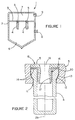
- Figure 1 is a sectional view of a first embodiment of a filter assembly device according to the present invention;
- Figure 2 is a sectional view showing the details of the sealing device employed in the filter assembly of Figure 1;
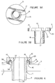
- Figure 3A is a top view of the sealing device of Figure 2;
- Figure 3B is a side view of the sealing device of Figure 3A;
- Figure 4 is a sectional view of a second embodiment of a filter assembly according to the present invention; and
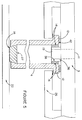
- Figure 5 is a sectional view showing details of a third embodiment of a filter assembly according to the present invention.
- Referring to Figure 1, a first exemplary filter assembly 1 embodying the present invention generally comprises a
pressure tank 2, a rigid sheet ortube sheet 3 extending across the interior of the tank, one ormore filter elements 4 disposed within thetank 2, and one ormore sealing devices 5 for sealing thefilter elements 4 to thetube sheet 3. Aninlet portion 6 of thepressure tank 2 may be sealed from anoutlet portion 7 of thepressure tank 2 by thetube sheet 3. An inlet 8 may be coupled to theinlet portion 6 for providing a fluid to the filter assembly 1. An outlet 9 may be coupled to theoutlet portion 7 for removing the fluid once it has passed through thefilter elements 4. Optionally, a back flow cleaning system (not shown) can be provided for supplying a high pressure fluid in the reverse direction for cleaning thefilter elements 4 and a cooling system (not shown) including coolant tubes can be provided in the tube sheet to maintain the temperature of the tube sheet below a predetermined value. - Each
filter element 4 is preferably narrow and elongated. It may include a closed or blind end, an open end, and a porous side wall. The side wall extends from the closed end to the open end and has an internal surface which defines a cavity that opens at the open end. Thefilter element 4 is preferably a filter constructed of a porous ceramic. The ceramic may be made of such compositions as Si₃N₄, mullite, cordierite (MgO, Al₂O₃, SiO₂), fireclay, aluminosilicate fibers, alumina, alumina/mullite, and silicon carbide-based materials. In a preferred embodiment, a hollow, porous, ceramic candle filter is used as thefilter element 4. - Figure 2 illustrates a sectional view of the details of the location of the
filter element 4 in thetube sheet 3 of a first embodiment of the filter assembly 1 of Figure 1. In this embodiment, thefilter element 4 is slidably inserted from the upper side of thetube sheet 3 through a hole or aperture 11 in thetube sheet 3. The open end of thefilter element 4 may include aflange 12 which prevents thefilter element 4 from passing completely through the aperture 11. Theflange 12 may be at any suitable angle to anaxis 28 of thefilter element 4. If the flange is at a right angle, the flange may engage the top of thetube sheet 3 or a lip formed in the wall defining the aperture 11. In the first embodiment, theflange 12 slopes upwardly at an acute angle and cooperates with a corresponding locatingprofile 13, e.g., an annular bevel, in the aperture wall. - In accordance with one aspect of the invention, a
sealing device 5 is preferably utilized to seal thefilter element 4 to thetube sheet 3. In the first embodiment, thesealing device 5 also functions as a hold-down element for securing eachfilter element 4 to thetube sheet 3. Thesealing device 5 may be fabricated as a single unitary piece or from two or more separate sections by, for example, machining, forming, stamping, or casting. If it is made from two or more separate sections, the sections of thesealing device 5 may be joined together by various methods such as a welded, threaded, or press fit connection. Further, thesealing device 5 may be variously configured without departing from the scope of the invention. For example, the illustratedsealing device 5, as shown in Figures 3-4, may include a flat planar ordisk section 15 and a hollowcylindrical section 16 which are unitarily formed. In a preferred embodiment, it may be desirable for a planar bottom surface of thedisk section 15 to have a larger diameter than thecylindrical section 16 and extend radially out beyond anouter surface 21 of the hollowcylindrical section 16, forming the bottomannular surface 20. - The
sealing device 5 includes aninternal passage 19 passing through the device from one open end to another. For example, in the illustratedsealing device 5, thepassage 19 extends axially through the hollowcylindrical section 16 and through the planar surface of thedisk section 15. The configuration of theinternal passage 19 may or may not be arranged in such a manner as to act as a venturi ornozzle 17. Thenozzle 17, or an alternative capillary (jet) configuration, can be used to increase the velocity of fluid flowing in the back flow direction and, thus, to enhance the blowback effectiveness when thefilter elements 4 are cleaned. In an alternative embodiment, it my be preferable for theinternal passage 19 to be configured as a plurality of internal passages. At least one of these plurality of internal passages may be formed into a nozzle, capillary, or jet configuration to provide a means for increasing back flow efficiency. In yet another embodiment, the internal passage may simply be a cylindrical bore. - Chemical corrosion may occur as a result of chemicals in the fluids processed through the filter assembly. As a result, the
sealing device 5 is preferably manufactured from a material which resists corrosion, for example, a high temperature, corrosion resistant, metal alloy such as RA333, available from Rolled Alloys of Temperance, MI. - The
sealing device 5 is shown in Figure 2 as it might appear installed in a filter assembly 1. Thesealing device 5 is placed over the top of thefilter element 4 with the hollowcylindrical section 16 extending for some distance into the internal cavity of thefilter element 4. For example, thecylindrical section 16 of thesealing device 5 may extend into the internal cavity of the filter element 4 a distance at least as great as the thickness of thetube sheet 3. It may be desirable to position a compressible cushioning and/or sealingmaterial 14 between thefilter element 4 and thetube sheet 3 and/or between the sealingdevice 5 and thefilter element 4. In a preferred embodiment, thecompressible material 14 may be a high temperature gasket material, most preferably a ceramic fiber material such as that available from 3M Corporation under the trade designation Interam. - In the illustrated embodiment, the
compressible material 14 is disposed between thefilter element 4 and thetube sheet 3 only at the portion of the tube sheet forming the locatingprofile 13. Of course, it is possible to have thecompressible material 14 located over the entire area between thefilter element 4 and thetube sheet 3. The openings in thetube sheet 3 may have portions that closely match the profile of the outer portion of thefilter element 4 and, in particular, theflange 12. Thecompressible material 14 placed between the tube sheet and thefilter element 4 acts to dampen any vibration which may be transferred to thefilter element 4 from thepressure tank 2. - In a preferred embodiment, it may be desirable to place the
compressible material 14 between thedisk section 15 of thesealing device 5 and the top of thefilter element 4 as well as between the outside of the hollowcylindrical section 16 of thesealing device 5 and the internal surface of thefilter element 4. Thecompressible material 14 acts as a cushion and/or a sealing gasket. Thecompressible material 14 may also act to prevent uneven stresses from being generated in thefilter element 4 due to non-uniformities on the interacting surfaces of thefilter element 4, thesealing device 5, and/or thetube sheet 3. The use of thecompressible material 14 is particularly useful when thefilter element 4 is a ceramic material. A ceramic material has a much lower ductility, i.e., less of an ability to deform under stress before fracture. When two surfaces are in contact, the area of contact is typically the highest points on the two surfaces. As a compressive force is applied, because of the ductility of the materials in contact, the high points in contact deform and allow a progressively larger portion of the two surfaces to come in contact, thereby reducing the stresses at the points of contact. Ceramic has very low ductility and tends to concentrate stresses over the initial contact points. When a compressible material is used in the interface of two ceramic surfaces or a ceramic surface and a metallic surface, the stress distribution is significantly improved. The use of the compressible material reduces the likelihood of fractures due to this stress. - A preload force may be used to compress the
compressible material 14 between the top of thefilter element 4 and the bottomannular surface 20 of the hold-down disc section 15. The preload force should preferably be of a magnitude to sufficiently compress thecompressible material 14 to prevent fluid flow between thebottom surface 20 of the hold-down disc section 15 and the top of thefilter element 4. The preload force may be maintained on thesealing device 5 by securing thesealing device 5 to thetube sheet 3 by any suitable method, including some type of mechanical method or mechanism such as welding, bolting, threading, latching, locking, or a pin-and-hole connection. The method of connection should be capable of withstanding vibrations and thermal shock resulting, for example, from pulse cleaning of the filter elements. In the illustrated embodiment, thedisk section 15 of the sealing device is welded to the tube sheet. The weld further functions as a seal preventing the fluid to be filtered from bypassing thefilter element 4. - In accordance with another aspect of the invention, the
sealing device 5 and thefilter element 4 preferably have different rates of thermal expansion and these different rates of thermal expansion effect a seal between thefilter element 4 and thesealing device 5 throughout the entire range of system temperatures. During start up or shutdown and at other times, the filter assembly is at relatively low temperature and pressure, e.g. atmospheric pressure and room temperature. A seal is then preferably maintained between the top of thefilter element 4 and thedisc section 15 of thesealing device 5 by compression of thecompressible material 14 due to the compressive preload placed on thesealing device 5 during installation. - On the other hand, operating temperature and pressure may be much higher. For example, the filter assembly 1 may be operated at a temperature of around 300°C to 1000°C and at a pressure of around 2 to 10 atmospheres. Embodiments of the present invention preferably utilize a sealing device and a
filter element 4 having different coefficients of thermal expansion and take advantage of the different rates of thermal expansion to further seal thefilter element 4 to the sealing device at these elevated temperatures. For example, in a preferred embodiment, thesealing device 5 may be constructed from a metal alloy while thefilter element 4 may be constructed from a ceramic. Ceramics typically have a much lower coefficient of thermal expansion than metals. Thus, as the temperature of the filter assembly 1 is increased during operation, thesealing device 5 may expand at a faster rate than does thefilter element 4 due to the different coefficients of thermal expansion of metals and ceramics. - The increase in temperature may result in a gradual increase in the relative distance between the top of the
filter element 4 and thebottom surface 20 of the hold-down disc section 15. This may reduce the compressive force on thecompressible material 14 between the top of thefilter element 4 and thebottom surface 20 of the hold-down disc section 15 and, thereby, reduce sealing efficiency. However, although the sealing efficiency may be reduced between the top of thefilter element 4 and the bottom of the hold-down disc section 15, the overall sealing efficiency between thefilter element 4 and thesealing device 5 is retained. - The increase in temperature also results in the hollow
cylindrical section 16 of thesealing device 5 expanding radially at a faster rate than thefilter element 4. This has the effect of reducing the clearance between the hollowcylindrical section 16 and the internal surface of thefilter element 4, thus compressing thecompressible material 14 and sealing thecylindrical section 16 of thesealing device 5 against the internal surface of thefilter element 4 even tighter. In this way an effective seal is maintained throughout the entire range of system temperatures. - Additionally, an effective seal is maintained even after repeated temperature cycling. Having both a low temperature compressible seal and a high temperature compressible seal is more reliable than conventional devices having only a high temperature seal or a low temperature seal. Without the use of both a low temperature seal and a high temperature seal, after repeated temperature cycling, the compressible material may be over compressed and reduced reliability may result. By having both the low temperature seal and the high temperature seal, neither seal is over compressed at any point in the temperature cycle. The low temperature seal seals at low temperatures, the high temperature seal seals at high temperatures, and an effective seal is maintained by both the low and high temperature seals at intermediate temperatures, resulting in increased reliability.
- Embodiments of the present invention have the added advantage that the stress from thermal shock and vibration is redistributed to an elongated area along the internal surface of the
filter element 4, reducing the stress at the flange. As previously cited, cracking of the flange is a common failure of the filter elements. Embodiments of the present invention can extend into the filter element 4 a significant distance beyond the flange, even beyond the depth of the tube sheet. In this manner, the stress caused by vibration and thermal shock is distributed over a wider area of the filter element. In addition, if a crack does occur at the flange, embodiments of the present invention may prevent any particulate leakage at operating temperatures since the hollow cylindrical section of the sealing device provides a seal that can extend below the flange of the filter element. - A second exemplary filter assembly embodying the present invention is illustrated in Figure 4. (Many of the components of the second embodiment are similar to the components of the first embodiment and are identified by identical reference numerals.) In this embodiment, the sealing device comprises a
tube sheet 3 having a hollowcylindrical portion 37 located about an aperture 11 in thetube sheet 3. While the hollow cylindrical portion may protrude from the lower surface of the tube sheet, in the illustrated embodiment it protrudes from the upper surface. The hollow cylindrical portion may be joined to the tube sheet by various methods such as a welded, threaded, or press fit connection, or may be formed integral therewith. - The
filter element 4 is preferably a ceramic filter, such as a ceramic candle filter, and it may be fabricated according to conventional techniques, such as molding, isostatic pressing, extrusion, or machining. Thefilter element 4 has an open end portion which includes aflange 12. Theflange 12, in turn, may include an opening such as anannular groove 23 located above the internal cavity of thefilter element 4 with the tube sheet facing the end portion of theflange 12. While the annular groove may face upwardly in the direction of the open end, in the illustrated embodiment it faces downwardly in the direction of the closed end of the filter element. - The hollow
cylindrical portion 37 of the tube sheet engages the annular groove in thefilter element 4. A compressible sealing and/orcushioning material 14 may be disposed anywhere between the tube sheet and the filter element, for example, between an outercylindrical wall surface 38 of the hollowcylindrical portion 37 and an inner facingsurface 39 of theannular groove 23. Additionally, a compressible sealing and/or cushioning material may be disposed between atop wall surface 40 of the hollowcylindrical portion 37 and a downward facing surface of theannular groove 23. In this embodiment, thefilter element 4 may be held-down using any suitable mechanism including the weight of the filter element. Thus, both a high temperature and low temperature seal may be obtained as with the first embodiment. Alternatively, when only a high temperature seal is desired the compressible sealing and/or cushioning material need only be disposed about the outercylindrical wall surface 38. - The sealing device of this second embodiment does not function as a hold-down device.
Consequently, a separate hold-down device, for example, a clamping mechanism such as a hold-down plate, may be coupled to the tube sheet for securing each filter element to the tube sheet and providing a preload force for urging the filter element toward the tube sheet as previously explained with regard to the first embodiment. However, with the hollowcylindrical portion 37 protruding upwardly and theannular groove 23 facing downwardly, the weight of thefilter element 4 urges theflange 12 toward the hollowcylindrical portion 37. If the downward gravitational force resulting from the weight of thefilter element 4 substantially exceeds any upward force on thefilter element 4 created by fluid flowing through the filter assembly, then the hold-down device may not be necessary. - In operation, the second embodiment functions similarly to the operation of the first embodiment. The
tube sheet 3 is made of a substance, e.g., a metal such as stainless steel, that expands at a higher rate with temperature than the substance, e.g., a ceramic, that thefilter element 4 is made of. As the temperature rises, the circumference of the hollowcylindrical portion 37 of thetube sheet 3 increases at a higher rate than the circumference of theannular groove 23 of thefilter element 4. Thus, at elevated temperatures, the differing coefficients of thermal expansion between thetube sheet 3 and thefilter element 4 cause thecompressible material 14 to be compressed between the outercylindrical wall surface 38 of the hollowcylindrical portion 37 and the inner facingsurface 39 of theannular groove 23 which faces the internal passage, thereby sealing the filter element to the tube sheet and more evenly distributing stress along the flange of the filter element. This second embodiment has the further advantage that the hollowcylindrical portion 37 is not disposed directly in the fluid flow path and, therefore, is less susceptible to corrosion and can be easily cooled using the same system which is utilized to cool thetube sheet 3. - A third embodiment of the invention is illustrated in Figure 5. (Many of the components of the third embodiment are similar to the components of the first embodiments and are identified by identical reference numerals.) In this embodiment, the sealing device also comprises a
tube sheet 3 having a hollowcylindrical portion 37 disposed about an aperture 11 in thetube sheet 3. The hollowcylindrical portion 37 defines aninternal passage 19 which is coupled to the aperture 11. Theinternal passage 19 may include a means for increasing back flow efficiency as discussed with respect to the first embodiment. Thetube sheet 3 and the hollowcylindrical section 36 may be integrally formed by, for example, machining, forming, stamping, or casting. If thetube sheet 3 and hollowcylindrical section 36 are made from two or more separate elements, they may be coupled by various methods such as a welded, threaded, latched, locked, or press fit connection. - The
filter element 4 has an open end which includes aflange 12. The hollowcylindrical portion 37 is capable of being fitted within and extending for some distance into the open end of thefilter element 4 with thetube sheet 3 facing the end portion of thefilter element 4. Thecompressible material 14 may be disposed anywhere between thetube sheet 3 and thefilter element 4, for example, between the inner facing surface of thefilter element 4 and an outercylindrical wall surface 38 of the hollowcylindrical section 37. - In this embodiment, the
filter elements 4 may be arranged so that the open end of eachfilter element 4 is abutting the lower surface of thetube sheet 3. Consequently, it is not necessary to insert thefilter elements 4 through the apertures 11 in thetube sheet 3; the filter elements may simply be fitted to the hollowcylindrical portions 37 from the underside of the tube sheet. To secure the filter elements to the tube sheet, asupport plate 26 may be coupled to thetube sheet 3 and/or asupport grid 22 may be coupled to thepressure tank 2 at the closed ends 27 of thefilter elements 4. Thesupport plate 26 andsupport grid 22 may be respectively coupled to thetube sheet 3 or bottom surface of thepressure tank 2 by various methods such as a welded, threaded, latched, locked, press fit, or pin-in-hole connection. A compressible sealing and/orcushioning material 14 may be located between theflange 12 of thefilter element 4 and thesupport plate 26 to evenly distribute the load and reduce stress on the flange and/or between theclosed end 27 of the filterelement support grid 22 to evenly distribute the weight of thefilter element 4. Thesupport plate 26 orsupport grid 22 may be configured to provide a preload force on the compressible material as previously explained with regard to the first embodiment. - In operation, the third embodiment functions similarly to the first and second embodiments. The
tube sheet 3 is made of a substance, e.g., a metal such as stainless steel, that expands at a higher rate with temperature than the substance, e.g., a ceramic, that thefilter element 4 is made of. As the temperature rises, the circumference of the hollowcylindrical section 37 increases at a higher rate than the circumference of the internal surface of thefilter element 4. Thus, at elevated temperatures, differing coefficients of thermal expansion between thetube sheet 3 and thefilter element 4 cause thecompressible material 14 to be compressed between the outercylindrical wall surface 38 of the hollowcylindrical section 37 and the inner facing surface of thefilter element 4. This seals the filter element to the tube sheet and evenly distributes stress along the filter element. This third embodiment has the further advantage that the hollowcylindrical section 37 can be easily cooled using the same system which cools thetube sheet 3. - While several exemplary filter assemblies embodying the present invention have been shown, it will be understood, of course, that the invention is not limited to these embodiments. Modification may be made by those skilled in the art, particularly in light of the foregoing teachings. It is, therefore, intended that the appended claims cover any such modifications which incorporate the features of this invention or encompass the true spirit and scope of the invention. For example, the sealing device may be configured in a mirror image in which a hollow cylindrical section may be coupled to both planar surfaces of the disc section or tube sheet. In this manner, the mirror image configuration may be utilized to connect two filter elements in a serial or parallel arrangement. Further, although a cylindrical shape is preferred, the filter elements and sealing devices illustrated herein are not limited to a cylindrical shape.
Claims (16)
- A filter assembly comprising:
a sealing device having first and second surfaces;
a filter element having first and second surfaces respectively disposed about the first surface of the sealing device and adjacent to the second surface of the sealing device; and
a compressible material respectively disposed between the first and second surfaces of the filter element and the first and second surfaces of the sealing device, wherein the filter element has a coefficient of thermal expansion that differs from the coefficient of thermal expansion of the sealing device, the compressible material being compressed between the second surfaces at a first predetermined temperature, and the differing coefficients of thermal expansion combine with an increase in temperature of the filter assembly to a second predetermined temperature, higher than the first predetermined temperature, to compress the compressible material between the first surfaces, for forming a seal at both the first and second predetermined temperatures. - The filter assembly as claimed in claim 1 wherein the sealing device comprises a metal and the filter element comprises a ceramic.
- The filter assembly as claimed in claim 1 wherein the first and second surfaces are substantially orthogonal.
- The filter assembly as claimed in claim 2 wherein the compressible material comprises ceramic fibers.
- The filter assembly as claimed in claim 1 including:
a tank;
an element disposed within the tank for dividing the tank between an inlet portion and an outlet portion, wherein the sealing device is coupled to the element. - The filter assembly as claimed in claim 1 wherein the sealing device has a first section having a cylinder-shaped configuration and a second section having a disk-shaped configuration coaxially mounted to the first section, an outer diameter of the first section being less than the outer diameter of the second section.
- The filter assembly as claimed in claim 1 wherein the body has an internal passage defining a fluid flow path.
- The filter assembly as claimed in claim 7 wherein the internal passage includes means for increasing back flow efficiency.
- The filter assembly as claimed in claim 1 wherein the sealing device includes a tube sheet, the filter element being disposed in an aperture in the tube sheet.
- The filter assembly as claimed in claim 1 wherein the sealing device is disposed within an annular groove within the filter element.
- The filter assembly as claimed in claim 1 wherein the compressible material being compressed between the second surfaces has a first compressive force at the first predetermined temperature and a second compressive force, less than the first compressive force, at the second predetermined temperature.
- The filter assembly device as claimed in claim 1 wherein the sealing device is disposed within an internal cavity within the filter element.
- A filter assembly comprising: a filter element having a porous ceramic tube having an open end and a flange including an annular groove; and
an annular metal sealing device disposed within the annular groove having a first surface. - The filter assembly of claim 13 including a compressible material disposed between the annular metal sealing device and the flange within the annular groove for sealing the flange to the annular metal sealing device.
- The filter assembly of claim 14 wherein the compressible material is disposed between an outer peripheral side wall of the annular metal sealing device and an inner peripheral side wall of the annular groove for compressing the compressible material at elevated temperatures.
- The filter assembly as claimed in claim 14 wherein the filter element has a closed end, an open end, and defines an internal cavity therebetween.
Applications Claiming Priority (2)
| Application Number | Priority Date | Filing Date | Title |
|---|---|---|---|
| US988642 | 1992-12-11 | ||
| US07/988,642 US5401406A (en) | 1992-12-11 | 1992-12-11 | Filter assembly having a filter element and a sealing device |
Publications (2)
| Publication Number | Publication Date |
|---|---|
| EP0601733A1 true EP0601733A1 (en) | 1994-06-15 |
| EP0601733B1 EP0601733B1 (en) | 1999-05-12 |
Family
ID=25534352
Family Applications (1)
| Application Number | Title | Priority Date | Filing Date |
|---|---|---|---|
| EP93309305A Expired - Lifetime EP0601733B1 (en) | 1992-12-11 | 1993-11-22 | A filter assembly having a filter element and a sealing device |
Country Status (6)
| Country | Link |
|---|---|
| US (1) | US5401406A (en) |
| EP (1) | EP0601733B1 (en) |
| JP (1) | JPH0768106A (en) |
| CA (1) | CA2109536A1 (en) |
| DE (1) | DE69324895T2 (en) |
| FI (1) | FI935540A7 (en) |
Cited By (11)
| Publication number | Priority date | Publication date | Assignee | Title |
|---|---|---|---|---|
| EP0681858A1 (en) * | 1994-05-11 | 1995-11-15 | Minnesota Mining And Manufacturing Company | Candle filter assembly and filtration system |
| WO1996002314A1 (en) * | 1994-07-20 | 1996-02-01 | Pall Corporation | A filter assembly having a filter element and a sealing device |
| GB2293335B (en) * | 1994-09-22 | 1998-06-17 | Toyoda Boshoku Kk | Resin-made air cleaners |
| ES2120300A1 (en) * | 1994-06-15 | 1998-10-16 | Babcock & Wilcox Espanola | Improved filter |
| US5964909A (en) * | 1998-09-04 | 1999-10-12 | Brunner; David | Filter cartridge sealing method |
| US7182799B2 (en) | 2002-03-26 | 2007-02-27 | Shell Oil Company | Filter assembly comprising filter elements and a filter grid |
| WO2008116672A2 (en) | 2007-03-23 | 2008-10-02 | Volkmann Gmbh | Filter arrangement |
| EP2030664A1 (en) | 2007-08-30 | 2009-03-04 | Peter Rapp | Filter element with exchangeable filter head |
| US20130075321A1 (en) * | 2011-09-27 | 2013-03-28 | Kenneth Donald Hobbs | Self sealing membrane contactor with PTFE tubular membranes |
| CN104771969A (en) * | 2015-04-20 | 2015-07-15 | 北京京能未来燃气热电有限公司 | Refined filtration drum dedusting device and refined filtration drum dedusting method for inlet air filtering system of gas turbine |
| CN105126491A (en) * | 2015-09-15 | 2015-12-09 | 中国航天空气动力技术研究院 | High-temperature high-pressure fluid cleaning system |
Families Citing this family (35)
| Publication number | Priority date | Publication date | Assignee | Title |
|---|---|---|---|---|
| US6338906B1 (en) | 1992-09-17 | 2002-01-15 | Coorstek, Inc. | Metal-infiltrated ceramic seal |
| US5700373A (en) * | 1992-09-17 | 1997-12-23 | Coors Ceramics Company | Method for sealing a filter |
| US6247221B1 (en) * | 1992-09-17 | 2001-06-19 | Coors Tek, Inc. | Method for sealing and/or joining an end of a ceramic filter |
| US6143421A (en) * | 1992-09-17 | 2000-11-07 | Coorstek, Inc. | Electronic components incorporating ceramic-metal composites |
| US5795359A (en) * | 1994-11-15 | 1998-08-18 | Hosokawa Micron Limited | Apparatus for separating particulate and/or powdery material from an entraining gas |
| DE19715196C2 (en) * | 1997-04-11 | 1999-04-22 | Herding Gmbh | Filter element |
| DE19739510C2 (en) * | 1997-09-09 | 1999-06-24 | Freudenberg Carl Fa | Filter cartridge |
| US6183529B1 (en) * | 1999-06-01 | 2001-02-06 | Gkn Sinter Metals, Inc. | High temperature gas filter assembly |
| US6302402B1 (en) | 1999-07-07 | 2001-10-16 | Air Products And Chemicals, Inc. | Compliant high temperature seals for dissimilar materials |
| US6468322B1 (en) * | 2000-09-29 | 2002-10-22 | Siemens Westinghouse Power Corporation | Filter holder assembly having extended collar spacer ring |
| DE10063462A1 (en) * | 2000-12-19 | 2002-06-27 | Gkn Sinter Metals Gmbh | Filter candle with a sintered filter tube |
| SE518058C2 (en) * | 2000-12-22 | 2002-08-20 | Alfa Laval Ab | Component for supporting a filter member in a port channel to a plate heat exchanger, device comprising a tubular filter member and said component, and plate heat exchanger comprising a tubular filter member and said component |
| US6547286B1 (en) | 2001-12-27 | 2003-04-15 | Praxair Technology, Inc. | Joint for connecting ceramic element to a tubesheet |
| US20050200124A1 (en) * | 2004-03-12 | 2005-09-15 | Kleefisch Mark S. | High temperature joints for dissimilar materials |
| US20050232834A1 (en) * | 2004-03-30 | 2005-10-20 | Mizan Tahmid I | Mitigation of top of catalyst bed fouling |
| US7291197B2 (en) * | 2004-07-29 | 2007-11-06 | Caterpillar Inc. | Particulate trap filter element |
| JP5020059B2 (en) * | 2007-12-28 | 2012-09-05 | 三菱電機株式会社 | Gas insulated switchgear |
| DE102008014025A1 (en) * | 2008-03-13 | 2009-09-17 | Boehringer Ingelheim Pharma Gmbh & Co. Kg | Inhaler and strainer for an inhaler |
| KR100955944B1 (en) * | 2008-04-16 | 2010-05-04 | 희성정밀 주식회사 | Service valves for air conditioners |
| US8978898B2 (en) | 2009-08-25 | 2015-03-17 | Smc Kabushiki Kaisha | Filter |
| US9527022B2 (en) * | 2012-06-08 | 2016-12-27 | Uop Llc | Method and apparatus for producing pyrolysis oil having improved stability |
| JP6026811B2 (en) * | 2012-08-08 | 2016-11-16 | メタウォーター株式会社 | Ceramic filter dust collector |
| US20140158607A1 (en) * | 2012-12-11 | 2014-06-12 | Mahle International Gmbh | Filter with absorbing expansion volume |
| US9039814B2 (en) * | 2013-04-18 | 2015-05-26 | Saes Pure Gas, Inc. | System and method for welding a plurality of small diameter palladium alloy tubes to a common base plate in a space efficient manner |
| KR102055954B1 (en) * | 2013-11-29 | 2019-12-16 | 한국조선해양 주식회사 | Filter apparatus |
| GB2521129B (en) * | 2013-12-10 | 2015-12-09 | Siemens Plc | A current feed-through |
| JP6382613B2 (en) * | 2014-07-18 | 2018-08-29 | 日本特殊陶業株式会社 | Fluid separation device |
| CN108419412B (en) * | 2018-02-08 | 2020-01-14 | 惠州汉旭五金塑胶科技有限公司 | Water-cooling row with impurity filtering function |
| CN108722060A (en) * | 2018-07-08 | 2018-11-02 | 飞潮(无锡)过滤技术有限公司 | A kind of novel fire resistant ceramic fibre chimney filter |
| KR20220014890A (en) * | 2019-06-04 | 2022-02-07 | 벌티모어 에어코일 컴파니 인코포레이티드 | Tubular Membrane Heat Exchanger |
| MX2023000566A (en) * | 2020-07-13 | 2023-03-15 | Evoqua Water Tech Llc | Regenerative media filter with flow diffuser. |
| US11471798B2 (en) * | 2020-11-10 | 2022-10-18 | Regfilter, S.L. | Liquid filtration system |
| EP4255598A4 (en) | 2020-12-03 | 2025-01-15 | Baltimore Aircoil Company, Inc. | TUBULAR MEMBRANE HEAT EXCHANGER |
| US12343662B2 (en) * | 2021-05-13 | 2025-07-01 | Eaton Intelligent Power Limited | Filter unit with flow optimization |
| US12215555B2 (en) * | 2023-03-21 | 2025-02-04 | Saudi Arabian Oil Company | Systems and methods for operating candle filters to recover glycols from drilling operations |
Citations (5)
| Publication number | Priority date | Publication date | Assignee | Title |
|---|---|---|---|---|
| WO1986005118A1 (en) * | 1985-03-04 | 1986-09-12 | Ing. L. Dolci S.P.A. | Filtering device for plastic |
| EP0345491A2 (en) * | 1988-06-04 | 1989-12-13 | Herding GmbH | Filter for the separation of solids from heat gaseous or liquid media |
| DE9014198U1 (en) * | 1990-10-12 | 1991-03-07 | Thomas Josef Heimbach GmbH & Co, 5160 Düren | Filters, especially hot gas filters |
| EP0446422A1 (en) * | 1990-03-10 | 1991-09-18 | ERNST-APPARATEBAU GmbH & Co. | Soot filter for diesel engines |
| DE9216259U1 (en) * | 1991-12-03 | 1993-03-04 | Coal Industry (Patents) Ltd., London | Improvements in ceramic filter candle arrangements |
Family Cites Families (50)
| Publication number | Priority date | Publication date | Assignee | Title |
|---|---|---|---|---|
| US2526651A (en) * | 1945-08-02 | 1950-10-24 | Hydrocarbon Research Inc | Separating powdered catalysts from exothermically reactive gases |
| US2514366A (en) * | 1945-09-19 | 1950-07-11 | Robert W Beyland | Filter |
| US2548875A (en) * | 1947-01-07 | 1951-04-17 | Kellogg M W Co | Contacting gases and solids |
| USRE24954E (en) * | 1951-07-26 | 1961-03-28 | Apparatus for | |
| US3055745A (en) * | 1952-11-07 | 1962-09-25 | Vulcan Cincinnati Inc | Catalytic reactor |
| US2948555A (en) * | 1955-08-08 | 1960-08-09 | Chicago Rawhide Mfg Co | Controlled gap seal |
| US2892510A (en) * | 1957-08-08 | 1959-06-30 | Standard Oil Co | High temperature gas and solids filter |
| DE1507846B2 (en) * | 1965-03-15 | 1977-06-08 | FILTER FOR CLEANING HOT, DUST-CONTAINING GASES | |
| DE1584994B1 (en) * | 1965-12-22 | 1971-03-04 | Schumacher Sche Fabrik | Method and device for the biological purification of waste water |
| US3503516A (en) * | 1968-09-05 | 1970-03-31 | Henry Mfg Co Inc | Pressure filter and tubular filter elements therefor |
| GB1327046A (en) * | 1970-01-28 | 1973-08-15 | Ici Ltd | Filter seal |
| US3642141A (en) * | 1970-07-21 | 1972-02-15 | Per Corp. | Filter tube and connection thereof to tube sheet |
| US3780868A (en) * | 1972-04-19 | 1973-12-25 | Dorr Oliver Inc | Pressure filter having depending tubular filter elements |
| JPS5130220B2 (en) * | 1973-12-11 | 1976-08-30 | ||
| DE2638142A1 (en) * | 1976-05-06 | 1977-11-17 | Textron Inc | FILTER |
| DE2702210C3 (en) * | 1977-01-20 | 1980-10-09 | Schumacher'sche Fabrik Gmbh & Co Kg, 7120 Bietigheim-Bissingen | Filter bodies for the fine separation of mist and solid aerosols from gases, in particular compressed air, as well as processes for the production of such filter bodies |
| CH622134A5 (en) * | 1978-01-25 | 1981-03-13 | Bbc Brown Boveri & Cie | |
| US4336035A (en) * | 1979-03-12 | 1982-06-22 | Wheelabrator-Frye Inc. | Dust collector and filter bags therefor |
| US4461707A (en) * | 1981-10-30 | 1984-07-24 | Canadian Patents & Development Limited | Ultrafiltration and reverse osmosis tubular membrane module |
| US4449422A (en) * | 1982-05-17 | 1984-05-22 | General Motors Corporation | Transmission center support mounting |
| US4522719A (en) * | 1982-12-24 | 1985-06-11 | Nihon Schumacher K.K. | Filter with a tubular filter element |
| US4615261A (en) * | 1984-10-29 | 1986-10-07 | Stirling Thermal Motors, Inc. | Stirling engine with improved piston ring assembly |
| WO1987007180A1 (en) * | 1986-05-30 | 1987-12-03 | Schumacher'sche Fabrik Gmbh & Co. Kg | Device for filtering gases |
| US4673187A (en) * | 1985-07-09 | 1987-06-16 | Fluorocarbon Company | Bimetallic spiral wound gasket |
| JPS6219217A (en) * | 1985-07-17 | 1987-01-28 | Nippon Shiyuumatsuhaa Kk | Filter element in filtration device |
| US4645596A (en) * | 1985-08-26 | 1987-02-24 | Nihon Schumacher Kabushiki Kaisha | Filter apparatus |
| DE3533924A1 (en) * | 1985-09-24 | 1987-06-19 | Schumacher Sche Fab Verwalt | FILTER BODY AND METHOD FOR THE PRODUCTION THEREOF |
| US4725356A (en) * | 1986-02-10 | 1988-02-16 | Industrial Filter & Pump Mfg. Co. | Tubular pressure filter |
| DE3621726A1 (en) * | 1986-06-28 | 1988-01-14 | Deutsche Forsch Luft Raumfahrt | PISTON PUMP FOR CONVEYING A CRYOGENIC LIQUID |
| US4713174A (en) * | 1986-07-22 | 1987-12-15 | Industrial Filter & Pump Mfg. Co. | Mounting arrangement for a tube-type filter element |
| JPS63116712A (en) * | 1986-10-31 | 1988-05-21 | Nippon Shiyuumatsuhaa Kk | Separating and drying apparatus |
| US4735638A (en) * | 1986-11-18 | 1988-04-05 | The United States Of America As Represented By The United States Department Of Energy | Filter unit for use at high temperatures |
| JPH0212421U (en) * | 1988-07-05 | 1990-01-25 | ||
| US4946487A (en) * | 1988-11-14 | 1990-08-07 | Norton Company | High temperature filter |
| US4909813A (en) * | 1989-05-30 | 1990-03-20 | Industrial Filter & Pump Mfg. Co. | Jet pulse extender |
| GB8916839D0 (en) * | 1989-07-22 | 1989-09-06 | Foseco Int | Filters |
| US5037115A (en) * | 1989-09-11 | 1991-08-06 | Brandon Ronald E | Piston ring assemblies for high temperature seals |
| US5037461A (en) * | 1989-09-25 | 1991-08-06 | Industrial Filter & Pump Mfg. Co. | Filtration apparatus |
| US4960448A (en) * | 1989-10-16 | 1990-10-02 | Universal Porosics, Inc. | High temperature gas filter |
| DE3938264A1 (en) * | 1989-11-17 | 1991-05-23 | Babcock Werke Ag | DEVICE FOR FILTERING HOT, DUST-LOADED GASES |
| JPH0647052B2 (en) * | 1989-12-13 | 1994-06-22 | 新日本製鐵株式会社 | Dust filter device |
| EP0454346A1 (en) * | 1990-04-21 | 1991-10-30 | United Kingdom Atomic Energy Authority | Exhaust particulate filter |
| DE4017071A1 (en) * | 1990-05-26 | 1991-11-28 | Heimbach Gmbh Thomas Josef | FILTER CANDLE |
| US5185019A (en) * | 1990-10-22 | 1993-02-09 | Westinghouse Electric Corp. | Filtering apparatus |
| US5080557A (en) * | 1991-01-14 | 1992-01-14 | General Motors Corporation | Turbine blade shroud assembly |
| US5223138A (en) * | 1991-02-04 | 1993-06-29 | Zievers James F | Reinforced ceramic filter candle and method of making same |
| DE4120920A1 (en) * | 1991-06-25 | 1993-01-07 | Didier Werke Ag | SOOT PARTICLE FILTER |
| US5209844A (en) * | 1991-08-08 | 1993-05-11 | Zievers James F | Hot gas filter with jet pulse cleaning |
| US5202021A (en) * | 1991-08-26 | 1993-04-13 | Hosokawa Micron International Inc. | Integrated molded collar, filter bag, cage and locking ring assembly for baghouses |
| GB2262053B (en) * | 1991-12-03 | 1995-03-08 | Coal Ind | Improvements relating to ceramic candle filter arrangements |
-
1992
- 1992-12-11 US US07/988,642 patent/US5401406A/en not_active Expired - Fee Related
-
1993
- 1993-11-19 CA CA002109536A patent/CA2109536A1/en not_active Abandoned
- 1993-11-22 DE DE69324895T patent/DE69324895T2/en not_active Expired - Fee Related
- 1993-11-22 EP EP93309305A patent/EP0601733B1/en not_active Expired - Lifetime
- 1993-12-10 JP JP5310547A patent/JPH0768106A/en active Pending
- 1993-12-10 FI FI935540A patent/FI935540A7/en unknown
Patent Citations (5)
| Publication number | Priority date | Publication date | Assignee | Title |
|---|---|---|---|---|
| WO1986005118A1 (en) * | 1985-03-04 | 1986-09-12 | Ing. L. Dolci S.P.A. | Filtering device for plastic |
| EP0345491A2 (en) * | 1988-06-04 | 1989-12-13 | Herding GmbH | Filter for the separation of solids from heat gaseous or liquid media |
| EP0446422A1 (en) * | 1990-03-10 | 1991-09-18 | ERNST-APPARATEBAU GmbH & Co. | Soot filter for diesel engines |
| DE9014198U1 (en) * | 1990-10-12 | 1991-03-07 | Thomas Josef Heimbach GmbH & Co, 5160 Düren | Filters, especially hot gas filters |
| DE9216259U1 (en) * | 1991-12-03 | 1993-03-04 | Coal Industry (Patents) Ltd., London | Improvements in ceramic filter candle arrangements |
Cited By (15)
| Publication number | Priority date | Publication date | Assignee | Title |
|---|---|---|---|---|
| EP0681858A1 (en) * | 1994-05-11 | 1995-11-15 | Minnesota Mining And Manufacturing Company | Candle filter assembly and filtration system |
| ES2120300A1 (en) * | 1994-06-15 | 1998-10-16 | Babcock & Wilcox Espanola | Improved filter |
| WO1996002314A1 (en) * | 1994-07-20 | 1996-02-01 | Pall Corporation | A filter assembly having a filter element and a sealing device |
| GB2293335B (en) * | 1994-09-22 | 1998-06-17 | Toyoda Boshoku Kk | Resin-made air cleaners |
| US5964909A (en) * | 1998-09-04 | 1999-10-12 | Brunner; David | Filter cartridge sealing method |
| US7182799B2 (en) | 2002-03-26 | 2007-02-27 | Shell Oil Company | Filter assembly comprising filter elements and a filter grid |
| WO2008116672A2 (en) | 2007-03-23 | 2008-10-02 | Volkmann Gmbh | Filter arrangement |
| WO2008116672A3 (en) * | 2007-03-23 | 2008-11-27 | Volkmann Gmbh | Filter arrangement |
| US8349048B2 (en) | 2007-03-23 | 2013-01-08 | Volkmann Gmbh | Filter arrangement |
| EP2030664A1 (en) | 2007-08-30 | 2009-03-04 | Peter Rapp | Filter element with exchangeable filter head |
| US20130075321A1 (en) * | 2011-09-27 | 2013-03-28 | Kenneth Donald Hobbs | Self sealing membrane contactor with PTFE tubular membranes |
| US9061251B2 (en) * | 2011-09-27 | 2015-06-23 | Markel Corporation | Self sealing membrane contactor with PTFE tubular membranes |
| CN104771969A (en) * | 2015-04-20 | 2015-07-15 | 北京京能未来燃气热电有限公司 | Refined filtration drum dedusting device and refined filtration drum dedusting method for inlet air filtering system of gas turbine |
| CN105126491A (en) * | 2015-09-15 | 2015-12-09 | 中国航天空气动力技术研究院 | High-temperature high-pressure fluid cleaning system |
| CN105126491B (en) * | 2015-09-15 | 2017-03-22 | 中国航天空气动力技术研究院 | High-temperature high-pressure fluid cleaning system |
Also Published As
| Publication number | Publication date |
|---|---|
| CA2109536A1 (en) | 1994-06-12 |
| US5401406A (en) | 1995-03-28 |
| JPH0768106A (en) | 1995-03-14 |
| EP0601733B1 (en) | 1999-05-12 |
| FI935540A7 (en) | 1994-06-12 |
| DE69324895D1 (en) | 1999-06-17 |
| FI935540A0 (en) | 1993-12-10 |
| DE69324895T2 (en) | 1999-12-09 |
Similar Documents
| Publication | Publication Date | Title |
|---|---|---|
| EP0601733B1 (en) | A filter assembly having a filter element and a sealing device | |
| US5531798A (en) | Eliminating ash bridging in ceramic filters | |
| EP0124863B1 (en) | Method of treating dust-containing gas and apparatus thereof | |
| US4735635A (en) | Apparatus and process for filtering high temperature gas streams | |
| JPH0759290B2 (en) | Filters for filtering particulate matter from hot gas streams | |
| HU205274B (en) | Filter and filtering device for separating solid particles from gaseous or fluid media advantageously from hot media | |
| US5474585A (en) | Filtering apparatus | |
| US5752999A (en) | Hot gas filtering apparatus | |
| EP0402032A1 (en) | Vertically tiered particle filtering apparatus | |
| JPH0736884B2 (en) | High temperature and high pressure gas dust remover | |
| US20060191245A1 (en) | Block for the filtration of particles contained in exhaust gases from an internal combustion engine | |
| US5482537A (en) | Gas filtering apparatus | |
| US5284498A (en) | Cylindrical filters in a tube sheet for cleaning high temperature gases | |
| US5152815A (en) | Type 114 tiered filter | |
| WO1996002314A1 (en) | A filter assembly having a filter element and a sealing device | |
| JPH05345109A (en) | High temperature gas filtering apparatus | |
| JP2718615B2 (en) | Dust collector for hot gas | |
| JPS63236508A (en) | Structure of ceramic filter | |
| KR100254496B1 (en) | A device for removing particles from gas of high temperature and high pressure | |
| KR0155300B1 (en) | Ceramic candle filter installation structure for high temperature and high pressure dust collection | |
| CA2246643C (en) | Hot gas filtering apparatus | |
| JP3294016B2 (en) | High temperature dust filter holding device | |
| JP2003251125A (en) | Gas filter apparatus | |
| CN1223599A (en) | Hot gas filter and system assembly | |
| JPH06190230A (en) | Dust removing device |
Legal Events
| Date | Code | Title | Description |
|---|---|---|---|
| PUAI | Public reference made under article 153(3) epc to a published international application that has entered the european phase |
Free format text: ORIGINAL CODE: 0009012 |
|
| AK | Designated contracting states |
Kind code of ref document: A1 Designated state(s): DE ES FR GB IT SE |
|
| 17P | Request for examination filed |
Effective date: 19941121 |
|
| 17Q | First examination report despatched |
Effective date: 19951013 |
|
| GRAG | Despatch of communication of intention to grant |
Free format text: ORIGINAL CODE: EPIDOS AGRA |
|
| GRAG | Despatch of communication of intention to grant |
Free format text: ORIGINAL CODE: EPIDOS AGRA |
|
| GRAH | Despatch of communication of intention to grant a patent |
Free format text: ORIGINAL CODE: EPIDOS IGRA |
|
| GRAH | Despatch of communication of intention to grant a patent |
Free format text: ORIGINAL CODE: EPIDOS IGRA |
|
| GRAA | (expected) grant |
Free format text: ORIGINAL CODE: 0009210 |
|
| AK | Designated contracting states |
Kind code of ref document: B1 Designated state(s): DE ES FR GB IT SE |
|
| PG25 | Lapsed in a contracting state [announced via postgrant information from national office to epo] |
Ref country code: SE Free format text: THE PATENT HAS BEEN ANNULLED BY A DECISION OF A NATIONAL AUTHORITY Effective date: 19990512 Ref country code: ES Free format text: THE PATENT HAS BEEN ANNULLED BY A DECISION OF A NATIONAL AUTHORITY Effective date: 19990512 |
|
| REF | Corresponds to: |
Ref document number: 69324895 Country of ref document: DE Date of ref document: 19990617 |
|
| ET | Fr: translation filed | ||
| PLBE | No opposition filed within time limit |
Free format text: ORIGINAL CODE: 0009261 |
|
| 26N | No opposition filed | ||
| PGFP | Annual fee paid to national office [announced via postgrant information from national office to epo] |
Ref country code: FR Payment date: 20011113 Year of fee payment: 9 |
|
| PGFP | Annual fee paid to national office [announced via postgrant information from national office to epo] |
Ref country code: GB Payment date: 20011121 Year of fee payment: 9 |
|
| PGFP | Annual fee paid to national office [announced via postgrant information from national office to epo] |
Ref country code: DE Payment date: 20011210 Year of fee payment: 9 |
|
| REG | Reference to a national code |
Ref country code: GB Ref legal event code: IF02 |
|
| PG25 | Lapsed in a contracting state [announced via postgrant information from national office to epo] |
Ref country code: GB Free format text: LAPSE BECAUSE OF NON-PAYMENT OF DUE FEES Effective date: 20021122 |
|
| PG25 | Lapsed in a contracting state [announced via postgrant information from national office to epo] |
Ref country code: DE Free format text: LAPSE BECAUSE OF NON-PAYMENT OF DUE FEES Effective date: 20030603 |
|
| GBPC | Gb: european patent ceased through non-payment of renewal fee | ||
| PG25 | Lapsed in a contracting state [announced via postgrant information from national office to epo] |
Ref country code: FR Free format text: LAPSE BECAUSE OF NON-PAYMENT OF DUE FEES Effective date: 20030731 |
|
| REG | Reference to a national code |
Ref country code: FR Ref legal event code: ST |
|
| PG25 | Lapsed in a contracting state [announced via postgrant information from national office to epo] |
Ref country code: IT Free format text: LAPSE BECAUSE OF NON-PAYMENT OF DUE FEES;WARNING: LAPSES OF ITALIAN PATENTS WITH EFFECTIVE DATE BEFORE 2007 MAY HAVE OCCURRED AT ANY TIME BEFORE 2007. THE CORRECT EFFECTIVE DATE MAY BE DIFFERENT FROM THE ONE RECORDED. Effective date: 20051122 |