EP0603492A1 - Vorrichtung zum Mischen und Austragen pastöser Massen - Google Patents
Vorrichtung zum Mischen und Austragen pastöser Massen Download PDFInfo
- Publication number
- EP0603492A1 EP0603492A1 EP93117163A EP93117163A EP0603492A1 EP 0603492 A1 EP0603492 A1 EP 0603492A1 EP 93117163 A EP93117163 A EP 93117163A EP 93117163 A EP93117163 A EP 93117163A EP 0603492 A1 EP0603492 A1 EP 0603492A1
- Authority
- EP
- European Patent Office
- Prior art keywords
- mixer
- mixing
- dynamic mixer
- static mixer
- dynamic
- Prior art date
- Legal status (The legal status is an assumption and is not a legal conclusion. Google has not performed a legal analysis and makes no representation as to the accuracy of the status listed.)
- Withdrawn
Links
- 238000002156 mixing Methods 0.000 title claims abstract description 29
- 235000011837 pasties Nutrition 0.000 title claims abstract description 7
- 239000000126 substance Substances 0.000 title 1
- 230000003068 static effect Effects 0.000 claims abstract description 23
- 239000000853 adhesive Substances 0.000 claims 1
- 230000001070 adhesive effect Effects 0.000 claims 1
- 239000000565 sealant Substances 0.000 claims 1
- 238000011144 upstream manufacturing Methods 0.000 claims 1
- 238000007599 discharging Methods 0.000 abstract description 2
- 238000004140 cleaning Methods 0.000 description 5
- 239000000203 mixture Substances 0.000 description 5
- 238000010438 heat treatment Methods 0.000 description 3
- 230000000694 effects Effects 0.000 description 2
- 230000006978 adaptation Effects 0.000 description 1
- 238000011010 flushing procedure Methods 0.000 description 1
- 238000000034 method Methods 0.000 description 1
- 238000013021 overheating Methods 0.000 description 1
- 230000035515 penetration Effects 0.000 description 1
- 238000003825 pressing Methods 0.000 description 1
- 238000007789 sealing Methods 0.000 description 1
- 238000003756 stirring Methods 0.000 description 1
- 230000009974 thixotropic effect Effects 0.000 description 1
- 238000010792 warming Methods 0.000 description 1
Images




Classifications
-
- B—PERFORMING OPERATIONS; TRANSPORTING
- B05—SPRAYING OR ATOMISING IN GENERAL; APPLYING FLUENT MATERIALS TO SURFACES, IN GENERAL
- B05C—APPARATUS FOR APPLYING FLUENT MATERIALS TO SURFACES, IN GENERAL
- B05C17/00—Hand tools or apparatus using hand held tools, for applying liquids or other fluent materials to, for spreading applied liquids or other fluent materials on, or for partially removing applied liquids or other fluent materials from, surfaces
- B05C17/005—Hand tools or apparatus using hand held tools, for applying liquids or other fluent materials to, for spreading applied liquids or other fluent materials on, or for partially removing applied liquids or other fluent materials from, surfaces for discharging material from a reservoir or container located in or on the hand tool through an outlet orifice by pressure without using surface contacting members like pads or brushes
- B05C17/00503—Details of the outlet element
- B05C17/00506—Means for connecting the outlet element to, or for disconnecting it from, the hand tool or its container
- B05C17/00513—Means for connecting the outlet element to, or for disconnecting it from, the hand tool or its container of the thread type
-
- B—PERFORMING OPERATIONS; TRANSPORTING
- B01—PHYSICAL OR CHEMICAL PROCESSES OR APPARATUS IN GENERAL
- B01F—MIXING, e.g. DISSOLVING, EMULSIFYING OR DISPERSING
- B01F25/00—Flow mixers; Mixers for falling materials, e.g. solid particles
- B01F25/40—Static mixers
- B01F25/42—Static mixers in which the mixing is affected by moving the components jointly in changing directions, e.g. in tubes provided with baffles or obstructions
- B01F25/43—Mixing tubes, e.g. wherein the material is moved in a radial or partly reversed direction
- B01F25/432—Mixing tubes, e.g. wherein the material is moved in a radial or partly reversed direction with means for dividing the material flow into separate sub-flows and for repositioning and recombining these sub-flows; Cross-mixing, e.g. conducting the outer layer of the material nearer to the axis of the tube or vice-versa
-
- B—PERFORMING OPERATIONS; TRANSPORTING
- B01—PHYSICAL OR CHEMICAL PROCESSES OR APPARATUS IN GENERAL
- B01F—MIXING, e.g. DISSOLVING, EMULSIFYING OR DISPERSING
- B01F33/00—Other mixers; Mixing plants; Combinations of mixers
- B01F33/50—Movable or transportable mixing devices or plants
- B01F33/501—Movable mixing devices, i.e. readily shifted or displaced from one place to another, e.g. portable during use
- B01F33/5011—Movable mixing devices, i.e. readily shifted or displaced from one place to another, e.g. portable during use portable during use, e.g. hand-held
-
- B—PERFORMING OPERATIONS; TRANSPORTING
- B01—PHYSICAL OR CHEMICAL PROCESSES OR APPARATUS IN GENERAL
- B01F—MIXING, e.g. DISSOLVING, EMULSIFYING OR DISPERSING
- B01F33/00—Other mixers; Mixing plants; Combinations of mixers
- B01F33/80—Mixing plants; Combinations of mixers
- B01F33/82—Combinations of dissimilar mixers
- B01F33/822—Combinations of dissimilar mixers with moving and non-moving stirring devices in the same receptacle
-
- B—PERFORMING OPERATIONS; TRANSPORTING
- B01—PHYSICAL OR CHEMICAL PROCESSES OR APPARATUS IN GENERAL
- B01F—MIXING, e.g. DISSOLVING, EMULSIFYING OR DISPERSING
- B01F35/00—Accessories for mixers; Auxiliary operations or auxiliary devices; Parts or details of general application
- B01F35/71—Feed mechanisms
- B01F35/716—Feed mechanisms characterised by the relative arrangement of the containers for feeding or mixing the components
- B01F35/7164—Feed mechanisms characterised by the relative arrangement of the containers for feeding or mixing the components the containers being placed in parallel before contacting the contents
-
- B—PERFORMING OPERATIONS; TRANSPORTING
- B05—SPRAYING OR ATOMISING IN GENERAL; APPLYING FLUENT MATERIALS TO SURFACES, IN GENERAL
- B05C—APPARATUS FOR APPLYING FLUENT MATERIALS TO SURFACES, IN GENERAL
- B05C17/00—Hand tools or apparatus using hand held tools, for applying liquids or other fluent materials to, for spreading applied liquids or other fluent materials on, or for partially removing applied liquids or other fluent materials from, surfaces
- B05C17/005—Hand tools or apparatus using hand held tools, for applying liquids or other fluent materials to, for spreading applied liquids or other fluent materials on, or for partially removing applied liquids or other fluent materials from, surfaces for discharging material from a reservoir or container located in or on the hand tool through an outlet orifice by pressure without using surface contacting members like pads or brushes
- B05C17/00553—Hand tools or apparatus using hand held tools, for applying liquids or other fluent materials to, for spreading applied liquids or other fluent materials on, or for partially removing applied liquids or other fluent materials from, surfaces for discharging material from a reservoir or container located in or on the hand tool through an outlet orifice by pressure without using surface contacting members like pads or brushes with means allowing the stock of material to consist of at least two different components
-
- B—PERFORMING OPERATIONS; TRANSPORTING
- B05—SPRAYING OR ATOMISING IN GENERAL; APPLYING FLUENT MATERIALS TO SURFACES, IN GENERAL
- B05C—APPARATUS FOR APPLYING FLUENT MATERIALS TO SURFACES, IN GENERAL
- B05C17/00—Hand tools or apparatus using hand held tools, for applying liquids or other fluent materials to, for spreading applied liquids or other fluent materials on, or for partially removing applied liquids or other fluent materials from, surfaces
- B05C17/005—Hand tools or apparatus using hand held tools, for applying liquids or other fluent materials to, for spreading applied liquids or other fluent materials on, or for partially removing applied liquids or other fluent materials from, surfaces for discharging material from a reservoir or container located in or on the hand tool through an outlet orifice by pressure without using surface contacting members like pads or brushes
- B05C17/00553—Hand tools or apparatus using hand held tools, for applying liquids or other fluent materials to, for spreading applied liquids or other fluent materials on, or for partially removing applied liquids or other fluent materials from, surfaces for discharging material from a reservoir or container located in or on the hand tool through an outlet orifice by pressure without using surface contacting members like pads or brushes with means allowing the stock of material to consist of at least two different components
- B05C17/00566—Hand tools or apparatus using hand held tools, for applying liquids or other fluent materials to, for spreading applied liquids or other fluent materials on, or for partially removing applied liquids or other fluent materials from, surfaces for discharging material from a reservoir or container located in or on the hand tool through an outlet orifice by pressure without using surface contacting members like pads or brushes with means allowing the stock of material to consist of at least two different components with a dynamic mixer in the nozzle
-
- B—PERFORMING OPERATIONS; TRANSPORTING
- B29—WORKING OF PLASTICS; WORKING OF SUBSTANCES IN A PLASTIC STATE IN GENERAL
- B29B—PREPARATION OR PRETREATMENT OF THE MATERIAL TO BE SHAPED; MAKING GRANULES OR PREFORMS; RECOVERY OF PLASTICS OR OTHER CONSTITUENTS OF WASTE MATERIAL CONTAINING PLASTICS
- B29B7/00—Mixing; Kneading
- B29B7/30—Mixing; Kneading continuous, with mechanical mixing or kneading devices
- B29B7/34—Mixing; Kneading continuous, with mechanical mixing or kneading devices with movable mixing or kneading devices
- B29B7/38—Mixing; Kneading continuous, with mechanical mixing or kneading devices with movable mixing or kneading devices rotary
- B29B7/40—Mixing; Kneading continuous, with mechanical mixing or kneading devices with movable mixing or kneading devices rotary with single shaft
- B29B7/401—Mixing; Kneading continuous, with mechanical mixing or kneading devices with movable mixing or kneading devices rotary with single shaft having a casing closely surrounding the rotor, e.g. with a plunger for feeding the material
-
- B—PERFORMING OPERATIONS; TRANSPORTING
- B29—WORKING OF PLASTICS; WORKING OF SUBSTANCES IN A PLASTIC STATE IN GENERAL
- B29B—PREPARATION OR PRETREATMENT OF THE MATERIAL TO BE SHAPED; MAKING GRANULES OR PREFORMS; RECOVERY OF PLASTICS OR OTHER CONSTITUENTS OF WASTE MATERIAL CONTAINING PLASTICS
- B29B7/00—Mixing; Kneading
- B29B7/30—Mixing; Kneading continuous, with mechanical mixing or kneading devices
- B29B7/34—Mixing; Kneading continuous, with mechanical mixing or kneading devices with movable mixing or kneading devices
- B29B7/38—Mixing; Kneading continuous, with mechanical mixing or kneading devices with movable mixing or kneading devices rotary
- B29B7/40—Mixing; Kneading continuous, with mechanical mixing or kneading devices with movable mixing or kneading devices rotary with single shaft
- B29B7/404—Mixing; Kneading continuous, with mechanical mixing or kneading devices with movable mixing or kneading devices rotary with single shaft with feeding or valve actuating means, e.g. with cleaning means
-
- B—PERFORMING OPERATIONS; TRANSPORTING
- B29—WORKING OF PLASTICS; WORKING OF SUBSTANCES IN A PLASTIC STATE IN GENERAL
- B29B—PREPARATION OR PRETREATMENT OF THE MATERIAL TO BE SHAPED; MAKING GRANULES OR PREFORMS; RECOVERY OF PLASTICS OR OTHER CONSTITUENTS OF WASTE MATERIAL CONTAINING PLASTICS
- B29B7/00—Mixing; Kneading
- B29B7/30—Mixing; Kneading continuous, with mechanical mixing or kneading devices
- B29B7/34—Mixing; Kneading continuous, with mechanical mixing or kneading devices with movable mixing or kneading devices
- B29B7/38—Mixing; Kneading continuous, with mechanical mixing or kneading devices with movable mixing or kneading devices rotary
- B29B7/40—Mixing; Kneading continuous, with mechanical mixing or kneading devices with movable mixing or kneading devices rotary with single shaft
- B29B7/405—Mixing heads
- B29B7/407—Mixing heads with a casing closely surrounding the rotor, e.g. with conical rotor
-
- B—PERFORMING OPERATIONS; TRANSPORTING
- B29—WORKING OF PLASTICS; WORKING OF SUBSTANCES IN A PLASTIC STATE IN GENERAL
- B29B—PREPARATION OR PRETREATMENT OF THE MATERIAL TO BE SHAPED; MAKING GRANULES OR PREFORMS; RECOVERY OF PLASTICS OR OTHER CONSTITUENTS OF WASTE MATERIAL CONTAINING PLASTICS
- B29B7/00—Mixing; Kneading
- B29B7/74—Mixing; Kneading using other mixers or combinations of mixers, e.g. of dissimilar mixers ; Plant
- B29B7/7438—Mixing guns, i.e. hand-held mixing units having dispensing means
- B29B7/7442—Mixing guns, i.e. hand-held mixing units having dispensing means with driven stirrer
-
- B—PERFORMING OPERATIONS; TRANSPORTING
- B29—WORKING OF PLASTICS; WORKING OF SUBSTANCES IN A PLASTIC STATE IN GENERAL
- B29B—PREPARATION OR PRETREATMENT OF THE MATERIAL TO BE SHAPED; MAKING GRANULES OR PREFORMS; RECOVERY OF PLASTICS OR OTHER CONSTITUENTS OF WASTE MATERIAL CONTAINING PLASTICS
- B29B7/00—Mixing; Kneading
- B29B7/74—Mixing; Kneading using other mixers or combinations of mixers, e.g. of dissimilar mixers ; Plant
- B29B7/7438—Mixing guns, i.e. hand-held mixing units having dispensing means
- B29B7/7447—Mixing guns, i.e. hand-held mixing units having dispensing means including means for feeding the components
-
- B—PERFORMING OPERATIONS; TRANSPORTING
- B01—PHYSICAL OR CHEMICAL PROCESSES OR APPARATUS IN GENERAL
- B01F—MIXING, e.g. DISSOLVING, EMULSIFYING OR DISPERSING
- B01F2101/00—Mixing characterised by the nature of the mixed materials or by the application field
- B01F2101/2305—Mixers of the two-component package type, i.e. where at least two components are separately stored, and are mixed in the moment of application
-
- B—PERFORMING OPERATIONS; TRANSPORTING
- B01—PHYSICAL OR CHEMICAL PROCESSES OR APPARATUS IN GENERAL
- B01F—MIXING, e.g. DISSOLVING, EMULSIFYING OR DISPERSING
- B01F27/00—Mixers with rotary stirring devices in fixed receptacles; Kneaders
- B01F27/05—Stirrers
- B01F27/11—Stirrers characterised by the configuration of the stirrers
- B01F27/114—Helically shaped stirrers, i.e. stirrers comprising a helically shaped band or helically shaped band sections
- B01F27/1143—Helically shaped stirrers, i.e. stirrers comprising a helically shaped band or helically shaped band sections screw-shaped, e.g. worms
-
- B—PERFORMING OPERATIONS; TRANSPORTING
- B01—PHYSICAL OR CHEMICAL PROCESSES OR APPARATUS IN GENERAL
- B01F—MIXING, e.g. DISSOLVING, EMULSIFYING OR DISPERSING
- B01F27/00—Mixers with rotary stirring devices in fixed receptacles; Kneaders
- B01F27/05—Stirrers
- B01F27/11—Stirrers characterised by the configuration of the stirrers
- B01F27/117—Stirrers provided with conical-shaped elements, e.g. funnel-shaped
-
- B—PERFORMING OPERATIONS; TRANSPORTING
- B01—PHYSICAL OR CHEMICAL PROCESSES OR APPARATUS IN GENERAL
- B01F—MIXING, e.g. DISSOLVING, EMULSIFYING OR DISPERSING
- B01F27/00—Mixers with rotary stirring devices in fixed receptacles; Kneaders
- B01F27/27—Mixers with stator-rotor systems, e.g. with intermeshing teeth or cylinders or having orifices
- B01F27/272—Mixers with stator-rotor systems, e.g. with intermeshing teeth or cylinders or having orifices with means for moving the materials to be mixed axially between the surfaces of the rotor and the stator, e.g. the stator rotor system formed by conical or cylindrical surfaces
- B01F27/2722—Mixers with stator-rotor systems, e.g. with intermeshing teeth or cylinders or having orifices with means for moving the materials to be mixed axially between the surfaces of the rotor and the stator, e.g. the stator rotor system formed by conical or cylindrical surfaces provided with ribs, ridges or grooves on one surface
Definitions
- the invention relates to a device for mixing and discharging two or more pasty masses according to the preamble of claim 1.
- Devices of this type are known. All devices require mixing devices to activate the reaction effect, which in turn is responsible for the viscosity curve and the curing time.
- the dynamic and static mixers previously used as mixing devices do their job only incompletely. The following examples may demonstrate this.
- DE 28 09 228 C2 shows a dynamic mixer with a circumferential, deep screw, divided by stationary guide disks. Disadvantages are the large volume of the mix, the friction heating and the difficult cleaning.
- the object of the invention is to create a device which combines the following advantages: Intense mix, minimal volume of curable mix, low warming, moderate flow pressure, high discharge rate, no caster with exit, easy cleaning and easy to use.
- the invention proposes to connect a single-stage static mixer to a dynamic mixer.
- the static mixer takes on the task of dividing the product streams into as many thin, thread-like individual streams as possible and distributing them without mutual contact in such a way that they are passed one by one to the other on a circular line to the dynamic mixer. There is no curable product mixture in the static mixer.
- the flow pressure required for the single-stage static mixer is low.
- the division and distribution of the product streams is preferably carried out via concentric annular spaces of the static mixer with a large number of distribution bores for the annular transfer area to the dynamic mixer.
- the dynamic mixer preferably has a conical mixing space in which a cone rotor with a small wall clearance in the centric direction with baffles of low height rotates at low speed.
- the cone rotor mixer therefore works to keep curable mixed goods with a low annular space. Thanks to the excellently pre-distributed masses in the static mixer, notably such a small mixing volume with a low rotor speed is sufficient for a good mixing effect.
- a discharge screw is also proposed, which is designed to minimize mixed goods and avoid product return with the smallest possible depth. The discharge screw is firmly connected to the mixer rotor.
- the rotor of the dynamic mixer is normally driven centrally.
- An eccentric drive is possible via a gear train, which also serves as a mixing aid.
- FIG. 1 the overall view of a device according to the invention with pneumatic actuation is shown.
- the cartridge chamber 1 is pressed out via the compressed air cylinder 2.
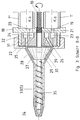
- the pasty mass located in the cartridge is divided into product threads in the static mixer 3 and distributed to the spherical dynamic mixer 4 and discharged through the screw 5.
- the whole is held together by the racks 7 with the tensioning levers 8.
- the dynamic mixer is driven by the pneumatic motor 9 via the elastic shaft 10.
- the compressed air cylinder 2 and the pneumatic motor 9 are firmly connected by the clamp 11.
- the device is actuated by means of the valve lever 13 located on the handle 12.
- the compressed air supplied at the connection 14 acts upon the opening of the valve 15 by pressing the lever 13 both the pneumatic motor 9 and the compressed air cylinder 2 via the line 16.
- the disks 17 and 18 are connecting elements between the compressed air cylinder 2 and the cartridge chambers 1 or between the cartridge chamber 1 and static mixer 3.
- FIG. 2 shows the section AA of the device according to FIG. 1.
- the cartridge chamber 1 is for the product mass a and the chamber 1 'for the product mass b. Both chambers are fixed in the disk 18, held axially by the tie rods 7.
- the bores 19 and 20 in the disk 18 serve to transfer the product masses a and b into the subsequent static mixer.
- Passage 21 is arranged centrally for the drive shaft 10 of the dynamic mixer.
- FIG. 3 shows the section B-B of FIG. 1.
- the chambers 1 and 1 pass their masses a and b through the bores 19 and 20 in the screw 18 to the annular chambers 23 and 24 located in the angular element 22 of the static mixer 3. From there they flow through a large number of bores 25 and 26 to the mixing chamber 27 of the dynamic mixer 4.
- This mixing chamber is delimited by the mixer jacket 28 and the mixing cone rotor 29 30 marked, occupied.
- the entire mixing area is held together by screwing onto the threaded shoulder 32 of the disk 18 via a metal-sealing adaptation of the angle element 22.
- the hole 39 in the angle element 22 serves as a flushing hole to prevent the entry of hardenable products into the space between the static element - angle element 22 and the dynamics - rotor 29.
- the screw body 35 fastened in the mixing rotor 29, has the smallest possible flight depth in order to minimize curable product masses.
- the screw length is designed so that when the cartridge container 1 and 1 'is put under pressure, there is no after-running at the nozzle 34.
- the low flight depth of the screw body 35 in conjunction with the usually thixotropic flow behavior of the products processed here, allows very short screws.
- FIG. 4 shows the section CC of FIG. 1.
- the drive shaft 10 is located centrally in the passage 21.
- the angle element 22 there are the annular spaces 23 and 24, of which the product components, divided into thin strands by a plurality of bores 25 and 26, are further guided will.
- the union nut 31 on the threaded ring 32 presses the angle element 22.
- Figure 5 shows a section similar to Figure 2, but with an eccentric drive of the dynamic mixer.
- the gearwheel 36 is attached to the mixing rotor 29 and is driven via the pinion 37 by means of the drive shaft 10 'introduced at 21'.
- Gear 36 is mounted on the pin 38 in the angle element 22.
- a union nut 31 is shown which is separate from the remaining mixer elements.
Landscapes
- Engineering & Computer Science (AREA)
- Mechanical Engineering (AREA)
- Chemical & Material Sciences (AREA)
- Chemical Kinetics & Catalysis (AREA)
- Dispersion Chemistry (AREA)
- Processing And Handling Of Plastics And Other Materials For Molding In General (AREA)
- Mixers Of The Rotary Stirring Type (AREA)
Abstract
Die Vorrichtung zum Mischen und Austragen pastöser Massen ist charakterisiert durch eine Mischeinrichtung, bestehend aus einer Kombination eines Statikmischers (3), der Kanäle besitzt für die weitestgehende Zerteilung und Vorverteilung der Massen in eine Vielzahl dünner Stränge, ohne gegenseitiger Massenberührung, mit einem Dynamikmischer (4) extrem kleinen Mischvolumens. <IMAGE>
Description
- Die Erfindung betrifft eine Vorrichtung zum Mischen und Austragen zweier oder mehr pastöser Massen gemäß Oberbegriff des Anspruches 1. Vorrichtungen dieser Art sind bekannt. Alle Vorrichtungen benötigen Mischeinrichtungen zur Aktivierung des Reaktionseffektes, der seinerseits für den Viskositätsverlauf und die Aushärtezeit verantwortlich ist. Die bisher als Mischeinrichtungen verwendeten Dynamik- und Statikmischer erfüllen ihre Aufgabe jedoch nur unvollkommen. Folgende Beispiele mögen das demonstrieren.
- Die DE 28 09 228 C2 zeigt einen Dynamikmischer mit umlaufender, tiefgängiger Schnecke, unterteilt durch ortsfeste Leitscheiben. Nachteilig sind das große Mischgutvolumen, die Reibungserwärmung und die schwierige Reinigung.
- Die DE 31 19 949 A1 zeigt einen Dynamikmischer mit einer Drahtwendelschnecke. Für eine ausreichende Mischleistung unter Vermeidung von Produktdurchschüssen im Drahtwendelkernbereich ist eine relativ lange Schnecke mit hoher Drehzahl erforderlich. Großes Mischgutvolumen mit hoher Erwärmung und die schwierige Reinigung sind so offensichtlich, daß dieser Mischer von vornherein als Wegwerfartikel konzipiert wurde.
- Die DE 37 23 677 C2 zeigt einen Dynamikmischer mit kurzem, mit Rührstiften besetzten Kegelrotor. Wenn auf dessen kurzer Mischstrecke die Zerteilung und Verteilung der Produktströme mit der erforderlichen Mischleistung erzielt werden sollen, so erfordert das hohe Rotordrehzahlen. Schädliche Mischprodukterwärmungen und Überhitzungen im Antriebswellenbereich sind unvermeidlich.
- Der Prospekt der Firma Beyer & Otto GmbH zeigt die Druckluftpistole TS-600/D mit einem langen Statikmischer. Statikmischer benötigen für brauchbare Mischleistungen bei pastösen Produkten wegen Fehlens turbulenter Strömungen zehn und mehr Mischstufen hintereinander und zur Vermeidung exzessiver Fließstücke relativ große Fließquerschnitte mit überproportional großem aushärtbaren Produktvolumen. Der Reinigungsaufwand ist erheblich.
- Die DE 24 00 150 A1 zeigt einen typischen Statikmischer. Das große Mischvolumen und die schwierige Reinigung sind offensichtlich. Den notwendigen hohen Druck zum Durchpressen pastöser Massen kennt der Fachmann.
- A. Die Erfindung hat sich die Aufgabe gestellt, eine Vorrichtung zu schaffen, die folgende Vorteile in sich vereint:
Intensive Mischung,
minimales Volumen aushärtbaren Mischgutes,
geringe Erwärmung,
moderater Fließdruck,
hohe Austragsleistung,
kein Nachlauf mit Austritt,
leichte Reinigung und
einfache Handhabung. - Demzufolge wird in der Erfindung vorgeschlagen, einem Dynamikmischer einen einstufigen Statikmischer vorzuschalten. Der Statikmischer übernimmt dabei die Aufgabe, die Produktströme in möglichst viele dünne, fadenförmige Einzelströme zu zerteilen und ohne gegenseitige Berührung so zu verteilen, daß sie einer neben dem anderen auf einer Kreislinie an den Dynamikmischer übergeben werden. Im Statikmischer entsteht dabei kein aushärtbares Produktgemisch. Der erforderliche Fließdruck für den einstufigen Statikmischer ist gering. Die Zerteilung und Verteilung der Produktströme wird vorzugsweise über konzentrische Ringräume des Statikmischers mit einer Vielzahl von Verteilbohrungen zum ringförmigen Übergabebereich an den Dynamikmischer vorgenommen.
- Der Dynamikmischer weist bevorzugt einen kegelförmigen Mischraum auf, in dem ein in zentrischer Richtung mit Schikanen geringer Höhe besetzter Kegelrotor mit geringem Wandabstand niedertourig umläuft. Der Kegelrotormischer arbeitet somit zwecks Geringhaltung aushärtbarer Mischware mit geringer Ringraumstärke. Dank der im Statikmischer hervorragend vorverteilten Massen genügt erfreulicherweise ein solch kleines Mischvolumen mit einer geringen Rotordrehzahl für eine gute Mischwirkung. Zur Entlastung vom Mischerinnendruck wird zusätzlich eine Austragsschnecke vorgeschlagen, die zur Minimierung gemischter Ware und Vermeidung von Produktrücklauf mit geringstmöglicher Gangtiefe konstruiert ist. Die Austragsschnecke ist fest verbunden mit dem Mischerrotor.
- Normalerweise wird der Rotor des Dynamikmischers zentrisch angetrieben. Ein exzentrischer Antrieb ist möglich über ein Zahnradvorgelege, das dabei zusätzlich als Mischhilfe dient.
- Weiterhin wird vorgeschlagen, im Statikmischer vom Ringzentrum eines Produktes ein oder zwei Bohrungen in Richtung des Mischrotorantriebes vorzusehen. Dadurch wird aushärtbare Ware vom Antriebs- bzw. Lagerzapfen ferngehalten und vorgesorgt, daß sich zwischen Statikmischer und Dynamikmischer irgend welche Ware dem Mischprozeß entziehen kann.
- B. Weitere Einzelheiten sind den Zeichnungen zu entnehmen, in denen die Erfindung anhand einer pneumatisch betätigten Vorrichtung dargestellt ist. Im einzelnen stellen die Zeichnungen dar:
- Figur 1
- Ansicht einer Gesamtvorrichtung,
- Figur 2
- einen Querschnitt nach A-A,
- Figur 3
- einen Längsschnitt nach B-B,
- Figur 4
- einen Querschnitt nach C-C und
- Figur 5
- einen Längsschnitt ähnlich der Figur 3.
- In Figur 1 ist die Gesamtansicht einer erfindungsgemäßen Vorrichtung mit pneumatischer Betätigung dargestellt. Die Kartuschenkammer 1 wird über den Druckluftzylinder 2 ausgepreßt. Die in der Kartusche befindliche pastöse Masse wird in dem Statikmischer 3 zerteilt in Produktfäden und verteilt den kugelförmigen Dynamikmischer 4 übergeben und durch die Schnecke 5 ausgetragen. Zusammengehalten wird das ganze durch die Zahnstangen 7 mit den Spannhebeln 8. Der Dynamikmischer wird angetrieben durch den Pneumatikmotor 9 über die elastische Welle 10. Der Druckluftzylinder 2 und der Pneumatikmotor 9 sind durch die Schelle 11 fest verbunden. Die Vorrichtung wird mittels des am Handgriff 12 befindlichen Ventilhebels 13 betätigt. Die am Anschluß 14 zugeführte Preßluft beaufschlagt nach Öffnen des Ventils 15 durch Drücken des Hebels 13 sowohl den Pneumatikmotor 9, als auch den Pressluftzylinder 2 über die Leitung 16. Die Scheiben 17 und 18 sind Anschlußelemente zwischen Pressluftzylinder 2 und Kartuschenkammern 1 bzw. zwischen Kartuschenkammer 1 und Statikmischer 3.
- Die Figur 2 zeigt den Schnitt A-A der Vorrichtung nach Figur 1. Die Kartuschenkammer 1 ist für die Produktmasse a und die Kammer 1' für die Produktmasse b. Beide Kammern sind fixiert in der Scheibe 18, axial gehalten durch die Zugstangen 7. Die Bohrungen 19 und 20 in der Scheibe 18 dienen dem Übertritt der Produktmassen a und b in den nachfolgenden Statikmischer. Durchgang 21 ist hier für die Antriebswelle 10 des Dynamikmischers zentrisch angeordnet.
- Die Figur 3 zeigt den Schnitt B-B der Figur 1. Die Kammern 1 und 1` geben ihre Masse a und b durch die Bohrungen 19 und 20 in der Schnecke 18 an die im Winkelelement 22 des Statikmischers 3 befindlichen Ringkammern 23 und 24 ab. Von dort fließen sie durch eine Vielzahl von Bohrungen 25 und 26 zum Mischraum 27 des Dynamikmischer 4. Dieser Mischraum wird begrenzt vom Mischermantel 28 und dem Mischkegelrotor 29. Letzterer kann mit radialen Mischelementen geringer radialer Höhe wie Noppen, Riefen oder Paddeln, in der Zeichnung mit 30 gekennzeichnet, besetzt sein. Angetrieben wir der Mischrotor 29 über eine elastische Welle 10, die durch den Durchgang 21 der Scheibe 18 eingeführt wird. Durch die Überwurfmutter 31, die fest mit dem Mantel 28 des Dynamikmischer 4 verbunden ist, wird der gesamte Mischbereich durch Aufschrauben auf den Gewindeansatz 32 der Scheibe 18 über metallisch dichtender Anpassung des Winkelelementes 22 zusammengehalten. - Die Bohrung 39 im Winkelelement 22 dient als Spülbohrung zur Vermeidung des Eintritts aushärtbarer Produkte in den Raum zwischen Statik - Winkelelement 22 und Dynamik - Rotor 29. - Der Schneckenmantel 33 der Ausstoßschnecke 5, hier aus einem Stück mit dem Mantel 28 des Dynamikmischers, endet mit dem Mundstück 34, das der jeweiligen Aufgabe angepaßt sein kann.
- Der Schneckenkörper 35, im Mischrotor 29 befestigt, hat zwecks Minimierung aushärtbarer Produktmassen eine möglichst geringe Gangtiefe. Die Schneckenlänge ist so ausgelegt, daß beim Abstellen trotz Druckbeaufschlagung Kartuschenbehälter 1 und 1` kein Nachlaufen an der Düse 34 zu verzeichnen ist. Die niedrige Gangtiefe des Schneckenkörpers 35 erlaubt in Verbindung mit dem üblicherweise thixotropen Fließverhalten der hier verarbeiteten Produkte recht kurze Schnecken.
- Die Figur 4 zeigt den Schnitt C-C der Figur 1. Zentrisch im Durchgang 21 liegt die Antriebswelle 10. Im Winkelelement 22 befinden sich die Ringräume 23 und 24, von denen die Produktkomponenten, durch eine Vielzahl von Bohrungen 25 und 26 in dünne Stränge zerteilt, weitergelenkt werden. Die Überwurfmutter 31 auf dem Gewindering 32 preßt das Winkelelement 22.
- Die Figur 5 zeigt einen Schnitt ähnlich der Figur 2, aber mit exzentrischem Antrieb des Dynamikmischers. Am Mischrotor 29 ist das Zahnrad 36 angebracht, welches über das Ritzel 37 mittels der bei 21' eingeführten Antriebswelle 10' angetrieben wird. Zahnrad 36 ist über den Zapfen 38 im Winkelelement 22 gelagert. Abweichend von Figur 3 ist hier eine von den restlichen Mischerelementen getrennte Überwurfmutter 31 dargestellt.
Claims (7)
- Vorrichtung zum Mischen und Austragen zweier oder mehr pastöser, in Kartuschen oder Schlauchpackungen vorproportionierter Massen, insbesondere zum Mischen von Mehrkomponenten - Kleb- und/oder Dichtstoffen, mit Vorratszylindern für die Produktkartuschen mit pneumatisch oder mechanisch beaufschlagten Dosierkolben und mit einem motorisch angetriebenen Dynamikmischer oder mit einem den Produktfließdruck nutzenden Statikmischer, dadurch gekenn zeichnet, daß einem Dynamikmischer ein einstufiger Statikmischer vorgeschaltet ist.
- Vorrichtung nach Anspruch 1, dadurch gekennzeichnet, daß der Statikmischer konzentrische Ringräume für jede Produktkomponente besitzt, von denen eine Vielzahl von Ventilbohrungen zum Ringzentrum des Dynamikmischers führen.
- Vorrichtung nach Anspruch 1 und 2, dadurch gekennzeichnet, daß der Dynamikmischer einen kegelförmigen Mischraum besitzt, in dem ein in zentrischer Richtung mit Schikanen geringer Höhe besetzten Kegelrotor mit geringem Wandabstand niedertourig umläuft.
- Vorrichtung nach Anspruch 1 bis 3, dadurch gekennzeichnet, daß dem Dynamikmischer eine Austragungsschnecke mit niedriger Gangtiefe nachgeschaltet ist.
- Vorrichtung nach Anspruch 1 bis 4, dadurch gekennzeichnet, daß der Dynamikmischer zentrisch angetrieben wird.
- Vorrichtung nach Anspruch 1 bis 4, dadurch gekennzeichnet, daß der Dynamikmischer exzentrisch über Zahnräder angetrieben wird.
- Vorrichtung nach Anspruch 1 bis 6, dadurch gekennzeichnet, daß von einem Ringzentrum des Statikmischers eine oder zwei Bohrungen in Richtung Lagerzapfen des Statikmischers verlaufen.
Applications Claiming Priority (2)
| Application Number | Priority Date | Filing Date | Title |
|---|---|---|---|
| DE4235736A DE4235736C1 (de) | 1992-10-23 | 1992-10-23 | Vorrichtung zum Mischen und Austragen pastöser Massen |
| DE4235736 | 1992-10-23 |
Publications (1)
| Publication Number | Publication Date |
|---|---|
| EP0603492A1 true EP0603492A1 (de) | 1994-06-29 |
Family
ID=6471131
Family Applications (1)
| Application Number | Title | Priority Date | Filing Date |
|---|---|---|---|
| EP93117163A Withdrawn EP0603492A1 (de) | 1992-10-23 | 1993-10-22 | Vorrichtung zum Mischen und Austragen pastöser Massen |
Country Status (2)
| Country | Link |
|---|---|
| EP (1) | EP0603492A1 (de) |
| DE (1) | DE4235736C1 (de) |
Cited By (12)
| Publication number | Priority date | Publication date | Assignee | Title |
|---|---|---|---|---|
| WO1997047378A1 (en) * | 1996-06-11 | 1997-12-18 | Smithkline Beecham Consumer Healthcare Gmbh | Mixing and dispensing device |
| WO2000021652A1 (de) * | 1998-10-14 | 2000-04-20 | Kettenbach Gmbh & Co. Kg | Vorrichtung zum vermischen zweier pastöser massen, insbesondere zum vermischen einer dental-abformmasse mit einer katalysatormasse |
| EP1004353A1 (de) * | 1998-11-04 | 2000-05-31 | Kress-elektrik GmbH + Co. Elektromotorenfabrik | Vorrichtung zum Mischen und dosierten Abgeben von fliessfähigen Mehrkomponentenmassen |
| US6523992B1 (en) * | 1999-11-12 | 2003-02-25 | Kettenbach Gmbh & Co. Kg | Device for mixing two pasty substances, particularly for mixing a dental impression substance with catalyst substance |
| US6540395B2 (en) * | 1999-12-23 | 2003-04-01 | Ernst Mühlbauer KG | Dynamic mixer for dental impression compounds |
| EP1892033A1 (de) * | 2006-08-21 | 2008-02-27 | ZHERMACK S.p.A. | Vorrichtung und Verfahren zum Mischen einer Mehrkomponentenmasse für dentale Gusswerkstücke |
| EP1925370A1 (de) * | 2006-10-06 | 2008-05-28 | Sulzer Chemtech AG | Mehrkomponentenkartusche |
| US7731413B2 (en) | 2008-02-20 | 2010-06-08 | Zhermack S.P.A. | Mixer for multi-components substance for dental casting |
| CN101801511B (zh) * | 2007-09-10 | 2013-03-27 | 苏舍米克斯帕克有限公司 | 动力混合器 |
| JP2013188744A (ja) * | 2006-12-15 | 2013-09-26 | Three M Innovative Properties Co | 硬化性多成分材料の混合及び吐出 |
| CN106714980A (zh) * | 2014-09-23 | 2017-05-24 | Sika技术股份公司 | 敷抹设备 |
| CN112871568A (zh) * | 2021-01-12 | 2021-06-01 | 深圳市诺盛豪自动化有限公司 | 高粘度螺杆点胶泵 |
Families Citing this family (31)
| Publication number | Priority date | Publication date | Assignee | Title |
|---|---|---|---|---|
| DE19504482B4 (de) * | 1995-02-10 | 2010-04-01 | Martinrea Industries, Inc., Manchester | Verfahren und Einrichtung zum klebenden Verbinden unter Verwendung nicht komprimierbarer Teilchen |
| DE29705741U1 (de) * | 1997-04-01 | 1998-08-06 | Muehlbauer Ernst Kg | Dynamischer Mischer für zahnärztliche Abdruckmassen |
| GB2339545B (en) * | 1998-07-15 | 2002-12-11 | Johnson & Johnson Medical Ltd | Mixing device |
| DE29912890U1 (de) * | 1999-07-23 | 1999-09-16 | Prestele, Eugen, 86179 Augsburg | Zweikomponentenkartusche |
| EP1072323B1 (de) | 1999-07-29 | 2003-09-10 | Wilhelm A. Keller | Kartuschen-Austraggerät mit Antrieb für dynamischen Mischer |
| ATE330700T1 (de) * | 1999-12-02 | 2006-07-15 | Mixpac Systems Ag | Dynamischer mischer. |
| US6443612B1 (en) * | 1999-12-02 | 2002-09-03 | Wilhelm A. Keller | Dynamic mixer |
| EP1306123A1 (de) * | 2001-10-24 | 2003-05-02 | Karlheinz Reiber | Applikator |
| DE10164385C1 (de) * | 2001-12-28 | 2003-03-06 | Kettenbach Gmbh & Co Kg | Vorrichtung zum Vermischen zweier pastöser Massen, insbesondere zum Vermischen einer Dental-Abformmasse mit einer Katalysatormasse |
| DE10209241C1 (de) * | 2002-03-04 | 2003-06-18 | Kleinmichel Gmbh | Vorrichtung zum Auftragen einer eine A-Komponente und eine B-Komponente enthaltenden Kleber-Raupe |
| WO2004080611A1 (en) * | 2003-03-06 | 2004-09-23 | Dentsply International Inc. | Dispensing and mixing tip |
| EP1510248B1 (de) * | 2003-08-14 | 2005-06-08 | 3M Espe Ag | Mischelement für einen Mehrkomponentenpastenmischer, und Mischer mit diesem Mischelement |
| JP4413561B2 (ja) * | 2003-09-01 | 2010-02-10 | 株式会社ジーシー | 歯科用印象材用撹拌ミキサー |
| EP1640060A1 (de) | 2004-09-22 | 2006-03-29 | 3M Espe Ag | Mischer für Mehrkomponentenpasten, Bausatz, und Verfahren zum Mischen von Pasten |
| US8322909B2 (en) | 2004-09-22 | 2012-12-04 | 3M Deutschland Gmbh | Mixer for multi-component pastes, kit, and method of mixing paste components |
| ATE454933T1 (de) * | 2005-10-07 | 2010-01-15 | Sulzer Mixpac Ag | Dynamischer mischer |
| US7387432B2 (en) * | 2006-10-11 | 2008-06-17 | Meditech International Ltd.-Samoa | Slidable securing device for a mixer to allow communication between a mixer housing and a mixer inlet portion of the mixer |
| DE202007007036U1 (de) | 2007-05-14 | 2007-07-26 | Nordson Corporation, Westlake | Mikrobreitenverstellbare Schlitzdüse |
| USD636500S1 (en) | 2008-10-01 | 2011-04-19 | 3M Innovative Properties Company | Dual chamber cartridge |
| IN2012DE01330A (de) | 2011-07-22 | 2015-09-25 | Sulzer Mixpac Ag | |
| CN102518816A (zh) * | 2011-12-27 | 2012-06-27 | 江苏东禾电声配件有限公司 | 双胶混合气动施胶枪专用气动阀 |
| DE102012004056A1 (de) * | 2012-03-02 | 2013-09-05 | Udo Tartler | Vorrichtung zum Mischen mindestens zweier fluider Komponenten, drehangetriebener Mischereinsatz dafür und System aus beidem |
| DE102013222111A1 (de) * | 2013-10-30 | 2015-04-30 | Henkel Ag & Co. Kgaa | Dynamische Mischvorrichtung |
| JP1534032S (de) | 2014-11-28 | 2015-09-28 | ||
| JP1534033S (de) | 2014-11-28 | 2015-09-28 | ||
| DE102016003538A1 (de) * | 2016-03-18 | 2017-09-21 | Udo Tartler | Mischeraufsatz für eine Mehrkomponentenkartuschen-Pistole |
| EP3505231A1 (de) * | 2017-12-29 | 2019-07-03 | Sulzer Mixpac AG | Mischer, mehrkomponentenausgabegerät und verfahren zur ausgabe von mehrkomponentenmaterial aus einem mehrkomponentenausgabegerät |
| EP4061198B1 (de) * | 2019-11-18 | 2025-05-07 | Boston Scientific Scimed, Inc. | Medizinprodukte für endoskopische verabreichung von mitteln |
| DE102020134316A1 (de) | 2020-12-18 | 2022-06-23 | Kulzer Gmbh | Rotorwelle mit Schneckengewinde für einen dynamischen Mischer zum Mischen niedrig- bis hochviskoser Komponenten |
| CN114653543B (zh) * | 2022-04-25 | 2023-05-12 | 江苏瑞合硕电子科技有限公司 | 旋转流体分配装置 |
| DE102024111141A1 (de) * | 2024-04-22 | 2025-10-23 | Audi Aktiengesellschaft | Applikationsdüse zum Applizieren einer gelförmigen oder pastösen Mehrkomponentenzusammensetzung |
Citations (8)
| Publication number | Priority date | Publication date | Assignee | Title |
|---|---|---|---|---|
| US1544765A (en) * | 1921-04-19 | 1925-07-07 | John C Lawrence | Apparatus for preparing poultry-feed mixtures |
| GB1102482A (en) * | 1965-04-15 | 1968-02-07 | H V Hardman Co Inc | Device for mixing and dispensing flowable materials |
| US3767085A (en) * | 1971-08-02 | 1973-10-23 | J Cannon | Mixing syringe |
| DE2537022A1 (de) * | 1975-07-31 | 1977-02-17 | Prod Res & Chem Corp | Geraet zum messen, mischen und ausgeben von zwei komponenten aufweisenden materialien |
| US4162128A (en) * | 1977-07-11 | 1979-07-24 | British Industrial Plastics Limited | Foam products |
| GB2064664A (en) * | 1979-12-07 | 1981-06-17 | Hilti Ag | Tool for dispensing multi-component compositions |
| EP0150738A2 (de) * | 1984-01-13 | 1985-08-07 | Colpo Company Limited | Misch- und Abgabegerät für Flüssigkeiten |
| US4541982A (en) * | 1982-12-06 | 1985-09-17 | Windmoller & Holscher | Process and apparatus for forming and rearranging partial streams of molten materials processed in an extruder for making thermoplastic and/or elastomeric products |
Family Cites Families (4)
| Publication number | Priority date | Publication date | Assignee | Title |
|---|---|---|---|---|
| DE2400150A1 (de) * | 1974-01-03 | 1975-07-17 | Braak Bv Geb | Mischvorrichtung |
| DE2809228A1 (de) * | 1978-03-03 | 1979-09-13 | Wilhelm Endlich | Vorrichtung zum dosieren und vermischen von mehrkomponentenmitteln |
| DE3119949A1 (de) * | 1981-05-20 | 1982-12-23 | Urlhart, Alfons, 8398 Pocking | Misch- und dosiergeraet fuer zweikomponentenkleber und giessharze mit wegwerfmischkopf. |
| DE3723677A1 (de) * | 1987-07-17 | 1989-01-26 | Audi Ag | Vorrichtung zum mischen und dosierten auftragen zweier pastoeser massen |
-
1992
- 1992-10-23 DE DE4235736A patent/DE4235736C1/de not_active Expired - Fee Related
-
1993
- 1993-10-22 EP EP93117163A patent/EP0603492A1/de not_active Withdrawn
Patent Citations (8)
| Publication number | Priority date | Publication date | Assignee | Title |
|---|---|---|---|---|
| US1544765A (en) * | 1921-04-19 | 1925-07-07 | John C Lawrence | Apparatus for preparing poultry-feed mixtures |
| GB1102482A (en) * | 1965-04-15 | 1968-02-07 | H V Hardman Co Inc | Device for mixing and dispensing flowable materials |
| US3767085A (en) * | 1971-08-02 | 1973-10-23 | J Cannon | Mixing syringe |
| DE2537022A1 (de) * | 1975-07-31 | 1977-02-17 | Prod Res & Chem Corp | Geraet zum messen, mischen und ausgeben von zwei komponenten aufweisenden materialien |
| US4162128A (en) * | 1977-07-11 | 1979-07-24 | British Industrial Plastics Limited | Foam products |
| GB2064664A (en) * | 1979-12-07 | 1981-06-17 | Hilti Ag | Tool for dispensing multi-component compositions |
| US4541982A (en) * | 1982-12-06 | 1985-09-17 | Windmoller & Holscher | Process and apparatus for forming and rearranging partial streams of molten materials processed in an extruder for making thermoplastic and/or elastomeric products |
| EP0150738A2 (de) * | 1984-01-13 | 1985-08-07 | Colpo Company Limited | Misch- und Abgabegerät für Flüssigkeiten |
Cited By (17)
| Publication number | Priority date | Publication date | Assignee | Title |
|---|---|---|---|---|
| WO1997047378A1 (en) * | 1996-06-11 | 1997-12-18 | Smithkline Beecham Consumer Healthcare Gmbh | Mixing and dispensing device |
| EA000589B1 (ru) * | 1996-06-11 | 1999-12-29 | Смитклайн Бичем Консьюмер Хелткер Гмбх | Смешивающее и дозирующее устройство |
| US6213633B1 (en) | 1996-06-11 | 2001-04-10 | Smithkline Beecham Consumer Healthcare Gmbh | Mixing and dispensing device |
| WO2000021652A1 (de) * | 1998-10-14 | 2000-04-20 | Kettenbach Gmbh & Co. Kg | Vorrichtung zum vermischen zweier pastöser massen, insbesondere zum vermischen einer dental-abformmasse mit einer katalysatormasse |
| US6394643B1 (en) * | 1998-10-14 | 2002-05-28 | Kettenbach Gmbh & Co. Kg | Device for mixing two pasty materials, especially for mixing a dental impression material with a catalyst material |
| EP1004353A1 (de) * | 1998-11-04 | 2000-05-31 | Kress-elektrik GmbH + Co. Elektromotorenfabrik | Vorrichtung zum Mischen und dosierten Abgeben von fliessfähigen Mehrkomponentenmassen |
| US6523992B1 (en) * | 1999-11-12 | 2003-02-25 | Kettenbach Gmbh & Co. Kg | Device for mixing two pasty substances, particularly for mixing a dental impression substance with catalyst substance |
| US6540395B2 (en) * | 1999-12-23 | 2003-04-01 | Ernst Mühlbauer KG | Dynamic mixer for dental impression compounds |
| EP1892033A1 (de) * | 2006-08-21 | 2008-02-27 | ZHERMACK S.p.A. | Vorrichtung und Verfahren zum Mischen einer Mehrkomponentenmasse für dentale Gusswerkstücke |
| EP1925370A1 (de) * | 2006-10-06 | 2008-05-28 | Sulzer Chemtech AG | Mehrkomponentenkartusche |
| JP2013188744A (ja) * | 2006-12-15 | 2013-09-26 | Three M Innovative Properties Co | 硬化性多成分材料の混合及び吐出 |
| CN101801511B (zh) * | 2007-09-10 | 2013-03-27 | 苏舍米克斯帕克有限公司 | 动力混合器 |
| US7731413B2 (en) | 2008-02-20 | 2010-06-08 | Zhermack S.P.A. | Mixer for multi-components substance for dental casting |
| CN106714980A (zh) * | 2014-09-23 | 2017-05-24 | Sika技术股份公司 | 敷抹设备 |
| US10456804B2 (en) | 2014-09-23 | 2019-10-29 | Sika Technology Ag | Application device |
| CN106714980B (zh) * | 2014-09-23 | 2020-04-07 | Sika技术股份公司 | 敷抹设备 |
| CN112871568A (zh) * | 2021-01-12 | 2021-06-01 | 深圳市诺盛豪自动化有限公司 | 高粘度螺杆点胶泵 |
Also Published As
| Publication number | Publication date |
|---|---|
| DE4235736C1 (de) | 1994-03-24 |
Similar Documents
| Publication | Publication Date | Title |
|---|---|---|
| DE4235736C1 (de) | Vorrichtung zum Mischen und Austragen pastöser Massen | |
| EP0993863B1 (de) | Mischer für Mehrkomponentenpasten | |
| EP0232733B1 (de) | Zweikomponenten-Austrageinrichtung | |
| EP1029585B1 (de) | Vorrichtung zum Ausgeben gemischter Mehrkomponentenmassen, insbesondere für zahnärztliche Zwecke | |
| DE4412261A1 (de) | Vorrichtung zum Zusammenführen wenigstens zweier Fließmedien | |
| EP0244849A1 (de) | Granuliervorrichtung mit einer gelochten Hohlwalze | |
| DE2809228C2 (de) | ||
| EP0022505B1 (de) | Vorrichtung zum Dosieren von Zweikomponenten-Produkten | |
| DE2450976A1 (de) | Verfahren bzw. vorrichtung zum mischen und/oder granulieren von pulverfoermigen bzw. koernigen substanzen mit mindestens einer fluessigkeit | |
| EP2618920B1 (de) | Kartuschensystem mit vorrichtung zum synchronisieren zweier fluidströme und mischverfahren | |
| DE3606001A1 (de) | Dosier- und mischpistole fuer mehrkomponenten-kunststoffe | |
| EP2219768B1 (de) | Mischeinrichtung zum vermischen von komponenten viskoser medien sowie darauf bezogener mischvorsatz und system | |
| DE19622582A1 (de) | Vorrichtung zum kontinuierlichen Bearbeiten von fließfähigen Materialien | |
| DE3630077A1 (de) | Vorrichtung zum gleichzeitigen dosierten abfuellen von fluessigen oder weichplastischen stoffen, wie butter, margarine, pasten oder dgl. ueber mundstuecke in benachbart zueinander angeordnete behaelter | |
| DE102011075873A1 (de) | Auspressgerät und Gebinde für ein Auspressgerät | |
| EP1285586A2 (de) | Verfahren und Vorrichtung zur kontinuierlichen Förderung von Süsswarenmassen | |
| EP0612659A1 (de) | Vorrichtung zum Einleiten eines Mediums in eine Kammer | |
| DE2457078B2 (de) | Vorrichtung zum dosieren pulverfoermiger additive fuer extruder oder aehnliche plastische massen verarbeitende maschinen | |
| EP3037177A1 (de) | Vorrichtung zum Ausbringen von fliessfähiger Masse und Mehrkomponentenkartusche | |
| DE3412222A1 (de) | Dosiergeraet fuer plastische massen | |
| EP1669131A1 (de) | Dynamischer Mischer | |
| DE2124466B2 (de) | Extruder fur die Verarbeitung von Kunststoffen und Elastomeren | |
| DE3014568A1 (de) | Spritz-kartusche | |
| EP3095528B1 (de) | Austragvorrichtung für pastöse massen | |
| EP0735307B1 (de) | Vorrichtung und Verfahren zum Abdichten einer Rohrleitung und/oder von Einmündungsstellen von Zubringerrohren |
Legal Events
| Date | Code | Title | Description |
|---|---|---|---|
| PUAI | Public reference made under article 153(3) epc to a published international application that has entered the european phase |
Free format text: ORIGINAL CODE: 0009012 |
|
| AK | Designated contracting states |
Kind code of ref document: A1 Designated state(s): AT BE CH DE DK FR GB IT LI NL SE |
|
| 17P | Request for examination filed |
Effective date: 19941220 |
|
| 17Q | First examination report despatched |
Effective date: 19951107 |
|
| STAA | Information on the status of an ep patent application or granted ep patent |
Free format text: STATUS: THE APPLICATION IS DEEMED TO BE WITHDRAWN |
|
| 18D | Application deemed to be withdrawn |
Effective date: 19990202 |