EP0603619A1 - Spannungswandler - Google Patents
Spannungswandler Download PDFInfo
- Publication number
- EP0603619A1 EP0603619A1 EP93119580A EP93119580A EP0603619A1 EP 0603619 A1 EP0603619 A1 EP 0603619A1 EP 93119580 A EP93119580 A EP 93119580A EP 93119580 A EP93119580 A EP 93119580A EP 0603619 A1 EP0603619 A1 EP 0603619A1
- Authority
- EP
- European Patent Office
- Prior art keywords
- switchgear
- converter
- voltage
- hood
- housing
- Prior art date
- Legal status (The legal status is an assumption and is not a legal conclusion. Google has not performed a legal analysis and makes no representation as to the accuracy of the status listed.)
- Granted
Links
- 238000004804 winding Methods 0.000 claims abstract description 10
- 239000004020 conductor Substances 0.000 claims description 7
- 230000000149 penetrating effect Effects 0.000 claims 1
- 238000010276 construction Methods 0.000 abstract description 3
- 239000012212 insulator Substances 0.000 description 3
- 238000009413 insulation Methods 0.000 description 2
- 238000012544 monitoring process Methods 0.000 description 2
- 239000004181 Flavomycin Substances 0.000 description 1
- 230000009172 bursting Effects 0.000 description 1
- 239000003795 chemical substances by application Substances 0.000 description 1
- 238000005516 engineering process Methods 0.000 description 1
- 238000007689 inspection Methods 0.000 description 1
- 239000012528 membrane Substances 0.000 description 1
- 238000000638 solvent extraction Methods 0.000 description 1
Images
Classifications
-
- H—ELECTRICITY
- H01—ELECTRIC ELEMENTS
- H01F—MAGNETS; INDUCTANCES; TRANSFORMERS; SELECTION OF MATERIALS FOR THEIR MAGNETIC PROPERTIES
- H01F38/00—Adaptations of transformers or inductances for specific applications or functions
- H01F38/20—Instruments transformers
- H01F38/22—Instruments transformers for single phase AC
- H01F38/24—Voltage transformers
- H01F38/26—Constructions
-
- H—ELECTRICITY
- H01—ELECTRIC ELEMENTS
- H01F—MAGNETS; INDUCTANCES; TRANSFORMERS; SELECTION OF MATERIALS FOR THEIR MAGNETIC PROPERTIES
- H01F27/00—Details of transformers or inductances, in general
Definitions
- the invention relates to a voltage converter for gas-insulated metal-encapsulated high- and medium-voltage switchgear according to the preamble of claim 1.
- This three-phase converter has a separate converter housing with its own gas filling, which is separated from the rest of the switchgear by means of a bulkhead insulator, and it has its own pressure overload device (bursting membrane and blow-out dome).
- the bulkhead insulator is penetrated gas-tight by special lead-through conductor sections that open into cranked, pluggable conductor ends within the switchgear housing. These converters are usually manufactured by specialist companies and connected to the rest of the switchgear at the construction site.
- a voltage converter which is also partitioned off from the switchgear, is known from DE-GM 82 30496 or JP 63-244 726 A (from Patent Abstract of Japan, E 712, Feb. 6, 1989, Vol. 13, No. 51 ) known.
- the considerations existing with the known voltage converters mentioned above also apply here.
- the voltage converter according to DE-AS 25 09 325 is used in the train of a pipe and thus cannot be placed on a switchgear such. B. those according to the above publications.
- the object of the invention is to make the voltage converter more cost-effective and, moreover, more compact.
- the active transducer elements are now only attached in a flangeable hood that is no longer partitioned off from the rest of the switchgear housing.
- the converter elements are therefore integrated in the rest of the switchgear or its gas insulation. This means that not only is there no special bulkhead insulator, but also the conductor sections that run tightly through it, as well as gas monitoring and special housing inspection measures. By eliminating the aforementioned conductor sections, smaller space requirements in the axial direction of the cylindrical converter housing are made possible.
- the pressure overload device which is no longer required, results in further space saving potential.
- the primary winding of the converter can now be connected directly to an angled pluggable conductor which cooperates with a corresponding plug receiving element of the switchgear.
- the active transducer elements e.g. B. the primary winding
- the active transducer elements easily overlap the flange level towards the switchgear interior, whereby the hood for the converter is even more compact.
- the converter remains mountable separately - as before - thanks to the plug-in device and the flange fastening of its hood.
- the low-voltage terminal box does not hinder the compact dimensions of the new converter if it is mounted next to the hood in the radial direction and does not protrude axially from the hood.
- the switchgear manufacturer also has a particular advantage.
- the customer can now buy the magnetic cores (together with coils) separately and install them in the switchgear assembly plant in the corresponding system housing - here the cover.
- the supplier of the magnetic cores who previously supplied the complete voltage converter, is now exempt from the construction of the converter housing, its acceptance tests, pressure tests, etc.
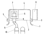
- a part of a switchgear housing 1 is shown, for. B. a disconnector or busbar housing that has a flange 3 surrounding an opening 2. This opening is covered with a cylindrical hood 4 open towards the switchgear side and screwed tightly to the flange 3 with its own flange 5.
- the magnetic cores 6 - of which only one is shown for the sake of simplicity - of the three-phase voltage converter are attached to the hood base. Both the primary winding 7 and the secondary winding 8 are arranged around a core leg.
- the high-voltage connection of the primary winding 7 takes place directly via a pluggable, cranked conductor 9 which is connected to the primary winding. Its free end engages in a corresponding connector receptacle 10 accommodated in the switchgear housing 1.
- a low-voltage terminal box 11 is arranged. It will be conveniently attached to the flange 5 by means of tabs.
- hood 4 and its internals are an integral part of an existing switchgear housing, these parts (hood and system housing) can already be installed in the switchgear manufacturer's plant to form a transport unit and can be tested electrically and with insulation gas technology, which saves additional costs.
Landscapes
- Engineering & Computer Science (AREA)
- Power Engineering (AREA)
- Transformers For Measuring Instruments (AREA)
- Coils Or Transformers For Communication (AREA)
- Gas-Insulated Switchgears (AREA)
Abstract
Description
- Die Erfindung betrifft einen Spannungswandler für gasisolierte metallgekapselte Hoch- bzw. Mittelspannungsschaltanlagen gemäß Oberbegriff des Anspruches 1.
- Solche Wandler sind aus Guthmann, Otto, Taschenbuch für Schaltanlagen, der BBC AG, Verlag W. Girardet, Essen, 7. Auflage 1979, Seite 367, Bild 8.11, der Druckschrift DESAN 1013 92 D der ABB Schaltanlagen GmbH vom März 1992, Seite 11 bekannt.
- Dieser dreiphasige Wandler besitzt ein separates Wandlergehäuse mit eigener Gasfüllung, das mittels eines Schottisolators von der übrigen Schaltanlage getrennt ist und er besitzt eine eigene Drucküberlastungsvorrichtung (Berstmembran sowie Ausblasdom). Der Schottisolator wird von besonderen Durchführungsleiterabschnitten gasdicht durchgriffen, die innerhalb des Schaltanlagengehäuses in abgekröpfte, steckbare Leiterenden einmünden. Diese Wandler werden in der Regel von Spezialfirmen gefertigt und an der Baustelle mit der übrigen Schaltanlage verbunden.
- Sie sind insbesondere wegen ihrer Gasschottung, der autaken Gasversorgung und Überwachung sehr aufwendig und ein erheblicher Kostenfaktor.
- Ein Spannungswandler, der ebenfalls gegenüber der Schaltanlage geschottet ist, ist aus dem DE-GM 82 30496 oder JP 63-244 726 A (aus Patent Abstract of Japan, E 712,, Feb. 6, 1989, Vol. 13, Nr. 51) bekannt. Die bei den oben genannten bekannten Spannungswandlern vorhandenen Überlegungen gelten hier ebenfalls.
- Der Spannungswandler nach der DE-AS 25 09 325 ist im Zug eines Rohres eingesetzt und somit nicht auf eine Schaltanlage aufsetzbar wie z. B. diejenigen gemäß den oben genannten Druckschriften.
- Die Aufgabe der Erfindung ist es, den Spannungswandler kostengünstiger und obendrein noch kompakter auszubilden.
- Dies gelingt mit den kennzeichnenden Merkmalen des Anspruches 1.
- Die aktiven Wandlerelemente sind nunmehr lediglich in einer flanschbaren Haube befestigt, die zum übrigen Schaltanlagengehäuse nicht mehr geschottet ist. Die Wandlerelemente sind also in die übrige Schaltanlage bzw. deren Gasisolierung integriert. Somit entfällt nicht nur ein besonderer Schottisolator, sondern auch die dicht durch diesen hindurchführenden Leiterabschnitte, desweiteren Gasüberwachungs- sowie besondere Gehäuseprüfungsmaßnahmen. Durch den Entfall der vorgenannten Leiterabschnitte sind geringere Raumbedürfnisse in axialer Richtung des zylindrischen Wandlergehäuses ermöglicht. Die nunmehr nicht mehr benötigte Drucküberlastungseinrichtung ergibt weiteres Raumersparnispotential.
- Die Primärwicklung des Wandlers kann nunmehr unmittelbar an einen abgekröpften steckbaren Leiter angeschlossen sein, der mit einem entsprechenden Steckeraufnahmeelement der Schaltanlage zusammenarbeitet.
- Da es keine Begrenzungen durch einen Schottisolator mehr gibt, können die aktiven Wandlerelemente, z. B. die Primärwicklung, ohne weiteres die Flanschebene zum Schaltanlageninneren hin übergreifen, wodurch die Haube für den Wandler noch gedrungener ausführbar ist.
- Gleichwohl bleibt der Wandler durch die Steckeinrichtung sowie die Flanschbefestigung seiner Haube - wie bisher - separat montierbar.
- Der Niederspannungsklemmkasten behindert die kompakten Abmessungen des neuen Wandlers nicht, wenn er in radialer Richtung neben der Haube montiert wird und axial die Haube nicht überragt.
- Ein besonderer Vorteil ergibt sich noch für den Schaltanlagenbauer. Dieser kann nunmehr selbst die Magnetkerne (nebst Spulen) separat kaufen und im Montagewerk der Schaltanlage in das entsprechende Anlagengehäuse - hier Haube - montieren.
- Der Lieferant der Magnetkerne, der früher den kompletten Spannungswandler anlieferte, ist nunmehr vom Bau des Wandlergehäuses, dessen Abnahmen, Druckprüfungen etc. befreit.
- Die Erfindung soll anhand eines skizzenmäßig dargestellten Ausführungsbeispieles näher erläutert werden.
- Gezeigt ist ein Teil eines Schaltanlagengehäuses 1, z. B. eines Trennschalter- oder Sammelschienengehäuses, das einen eine Öffnung 2 umgebenden Flansch 3 aufweist. Diese Öffnung ist mit einer zur Schaltanlagenseite hin offenen zylindrischen Haube 4 abgedeckt und mit einem eigenen Flansch 5 am Flansch 3 dicht verschraubt. Am Haubenboden sind die Magnetkerne 6 - von denen der Einfachheit halber nur einer dargestellt ist - des dreiphasigen Spannungswandlers befestigt. Um einen Kernschenkel herum sind sowohl die Primärwicklung 7 als auch die Sekundärwicklung 8 angeordnet.
- Der Hochspannungsanschluß der Primärwicklung 7 erfolgt direkt über einen steckbaren, abgekröpften Leiter 9, der mit der Primärwicklung verbunden ist. Dessen freies Ende greift in eine, im Schaltanlagengehäuse 1 untergebrachte entsprechende Steckeraufnahme 10. Neben der Haube 4 und diese in axialer Richtung nicht überragend, ist ein Niederspannungsklemmkasten 11 angeordnet. Er wird zweckmäßigerweise vermittels Laschen am Flansch 5 befestigt sein.
- Da die Haube 4 samt deren Einbauten (aktive Wandlerelemente) ein integriertes Bestandteil eines bereits vorhandenen Schaltanlagengehäuses ist, können diese Teile (Haube und Anlagengehäuse) bereits im Herstellerwerk der Schaltanlage zu einer Transporteinheit verbaut und elektrisch sowie isoliergastechnisch geprüft werden, was weitere Kosten spart.
Claims (4)
- Spannungswandler für gasisolierte, metallgekapselte Hoch- bzw. Mittelspannungsschaltanlagen, dessen Aktivteile, wie Kerne bzw. Wicklungen, im wesentlichen in einem separaten Wandlergehäuseteil, das an ein Schaltanlagengehäuse anflanschbar ist, untergebracht sind, dadurch gekennzeichnet, daß das Wandlergehäuseteil als eine zum übrigen Schaltanlagengehäuse (1) hin offene Haube (4) ausgebildet und der Gasraum der Schaltanlage sich in den Spannungswandler in der Haube (4) hinein erstreckt.
- Spannungswandler nach Anspruch 1, dadurch gekennzeichnet, daß die Primärwicklung (7) des Wandlers hochspannungsseitig unmittelbar über einen zum Schaltanlagengehäuse (1) hin gerichteten steckbaren Leiter (9) angeschlossen ist, der mit einer fixen Steckeraufnahme (10) der Schaltanlage in Verbindung bringbar ist.
- Spannungswandler nach einem der Ansprüche 1 oder 2, dadurch gekennzeichnet, daß die kreisringförmige, ein Fenster des Kernes (6) durchgreifende Primärwicklung (7) über die zwischen Haube (4) und Schaltanlagengehäuse (1) gebildete Flanschebene hinaus in das Schaltanlagengehäuse (1) hineinragend ausgebildet ist.
- Spannungswandler nach einem der Ansprüche 1 bis 3, dadurch gekennzeichnet, daß der Niederspannungsklemmkasten (11) des Wandlers neben der Haube (4) angeordnet ist und deren Höhe in axialer Richtung nicht übersteigt.
Applications Claiming Priority (2)
| Application Number | Priority Date | Filing Date | Title |
|---|---|---|---|
| DE4243207A DE4243207A1 (de) | 1992-12-19 | 1992-12-19 | Spannungswandler |
| DE4243207 | 1992-12-19 |
Publications (2)
| Publication Number | Publication Date |
|---|---|
| EP0603619A1 true EP0603619A1 (de) | 1994-06-29 |
| EP0603619B1 EP0603619B1 (de) | 1998-02-11 |
Family
ID=6475924
Family Applications (1)
| Application Number | Title | Priority Date | Filing Date |
|---|---|---|---|
| EP93119580A Revoked EP0603619B1 (de) | 1992-12-19 | 1993-12-04 | Hoch- bzw. Mittelspannungsanlage mit einem Spannungswandler. |
Country Status (3)
| Country | Link |
|---|---|
| EP (1) | EP0603619B1 (de) |
| KR (1) | KR940016303A (de) |
| DE (2) | DE4243207A1 (de) |
Cited By (2)
| Publication number | Priority date | Publication date | Assignee | Title |
|---|---|---|---|---|
| EP2346053A1 (de) | 2010-01-18 | 2011-07-20 | ABB Technology AG | Gasisolierte Hochspannungsmesseinheit |
| EP2346128A1 (de) | 2010-01-18 | 2011-07-20 | ABB Technology AG | Gasisolierter Sensormodul |
Families Citing this family (2)
| Publication number | Priority date | Publication date | Assignee | Title |
|---|---|---|---|---|
| EP1016104B1 (de) * | 1997-09-16 | 2004-10-13 | KG Ritz Messwandler GmbH & Co. | Wandleranordnung mit trenneinrichtung |
| RU2124246C1 (ru) * | 1997-11-13 | 1998-12-27 | Арсон Александр Григорьевич | Высокольтный трансформатор напряжения наружной установки |
Citations (3)
| Publication number | Priority date | Publication date | Assignee | Title |
|---|---|---|---|---|
| JPS59121814A (ja) * | 1982-12-28 | 1984-07-14 | Toshiba Corp | ブツシング形変流器 |
| CH652852A5 (en) * | 1979-09-20 | 1985-11-29 | Siemens Ag | Inductive voltage converter for a fully insulated, metal-encapsulated high-voltage switching installation |
| EP0236974A2 (de) * | 1986-03-13 | 1987-09-16 | Mwb Messwandler-Bau Ag | Kombinierter Hochspannungsstrom- und -spannungswandler |
Family Cites Families (2)
| Publication number | Priority date | Publication date | Assignee | Title |
|---|---|---|---|---|
| DE2509325B2 (de) * | 1975-02-28 | 1977-06-02 | Siemens AG, 1000 Berlin und 8000 München | Spannungswandler |
| DE8230496U1 (de) * | 1982-10-29 | 1983-04-14 | Siemens AG, 1000 Berlin und 8000 München | Anordnung eines spannungswandlers bei einer gekapselten, gasisolierten mittelspannungs-schaltanlage |
-
1992
- 1992-12-19 DE DE4243207A patent/DE4243207A1/de not_active Withdrawn
-
1993
- 1993-12-04 DE DE59308141T patent/DE59308141D1/de not_active Revoked
- 1993-12-04 EP EP93119580A patent/EP0603619B1/de not_active Revoked
- 1993-12-16 KR KR1019930028073A patent/KR940016303A/ko not_active Withdrawn
Patent Citations (3)
| Publication number | Priority date | Publication date | Assignee | Title |
|---|---|---|---|---|
| CH652852A5 (en) * | 1979-09-20 | 1985-11-29 | Siemens Ag | Inductive voltage converter for a fully insulated, metal-encapsulated high-voltage switching installation |
| JPS59121814A (ja) * | 1982-12-28 | 1984-07-14 | Toshiba Corp | ブツシング形変流器 |
| EP0236974A2 (de) * | 1986-03-13 | 1987-09-16 | Mwb Messwandler-Bau Ag | Kombinierter Hochspannungsstrom- und -spannungswandler |
Non-Patent Citations (1)
| Title |
|---|
| PATENT ABSTRACTS OF JAPAN vol. 8, no. 243 (E - 277)<1680> 8 November 1984 (1984-11-08) * |
Cited By (4)
| Publication number | Priority date | Publication date | Assignee | Title |
|---|---|---|---|---|
| EP2346053A1 (de) | 2010-01-18 | 2011-07-20 | ABB Technology AG | Gasisolierte Hochspannungsmesseinheit |
| EP2346128A1 (de) | 2010-01-18 | 2011-07-20 | ABB Technology AG | Gasisolierter Sensormodul |
| CN102163817A (zh) * | 2010-01-18 | 2011-08-24 | Abb技术有限公司 | 气体绝缘传感器模块 |
| CN102163817B (zh) * | 2010-01-18 | 2014-04-02 | Abb技术有限公司 | 气体绝缘传感器模块 |
Also Published As
| Publication number | Publication date |
|---|---|
| KR940016303A (ko) | 1994-07-23 |
| DE59308141D1 (de) | 1998-03-19 |
| EP0603619B1 (de) | 1998-02-11 |
| DE4243207A1 (de) | 1994-06-23 |
Similar Documents
| Publication | Publication Date | Title |
|---|---|---|
| EP0735637A2 (de) | Schaltvorrichtung mit einem geerdeten, isoliergasgefüllten Metallgehäuse | |
| DE4412784A1 (de) | Strom- und Spannungssensor für ein Hochspannungsschaltfeld und Hochspannungsschaltfeld mit einem solchen Strom- und Spannungssensor | |
| DE3313192A1 (de) | Gekapselte, gasisolierte mittelspannungsschaltanlage | |
| EP0678955B1 (de) | Metallgekapselte gasisolierte Schaltanlage | |
| DE2417023C3 (de) | In eine vollisolierte, metallgekapselte Hochspannungsschaltanlage einbaubarer Einleiterstromwandler | |
| DE3712190A1 (de) | Elektrischer wandler | |
| DE69401800T2 (de) | Mehrzweckstromdurchführung | |
| WO1999045617A1 (de) | Metallgekapselte, gasiolierte schaltanlagen mit gasgefüllten behältern | |
| EP0603619B1 (de) | Hoch- bzw. Mittelspannungsanlage mit einem Spannungswandler. | |
| DE3742610C1 (en) | Coupling capacitor for a voltage measuring and/or display device | |
| DE60104788T2 (de) | Gasisolierter Leistungsschalter mit integriertem elektronischem Stromwandler | |
| DE4414828C2 (de) | Hochspannungswandler | |
| EP0229220B1 (de) | Stromwandleranordnung | |
| DE1807996A1 (de) | Einleiterwandler | |
| DE9420193U1 (de) | Gasisolierte Leistungsschalter-Anlage | |
| DE8904684U1 (de) | Ringkernstromwandler zum Einbau in eine metallgekapselte, gasisolierte Hochspannungsschaltanlage | |
| DE4445082C1 (de) | Hochspannungs-Steckkontakt | |
| EP0755061B1 (de) | Einpoliger Spannungswandler | |
| WO1999047936A1 (de) | Stromsensor | |
| DE2628453A1 (de) | Vorrichtung zum pruefen des isoliervermoegens von gekapselten schaltanlagen | |
| DE3328785A1 (de) | Durchfuehrungsisolator fuer eine schottwandung in einem anlagenschrank fuer mittelspannungsschalt- und -verteileranlagen | |
| EP0215728A1 (de) | Metallgekapselte, druckgasisolierte Hochspannungsschaltanlage mit einem Messwandler | |
| EP0623981B1 (de) | Gasisolierte Hochspannungsschaltanlage | |
| DE19510659C1 (de) | Anordnung zur Ankopplung eines Rundsteuersenders | |
| DE6949835U (de) | Vollgekapselte, insbesondere druckgasisolierte schaltanlage |
Legal Events
| Date | Code | Title | Description |
|---|---|---|---|
| PUAI | Public reference made under article 153(3) epc to a published international application that has entered the european phase |
Free format text: ORIGINAL CODE: 0009012 |
|
| AK | Designated contracting states |
Kind code of ref document: A1 Designated state(s): CH DE FR IT LI NL |
|
| 17P | Request for examination filed |
Effective date: 19940722 |
|
| 17Q | First examination report despatched |
Effective date: 19951229 |
|
| GRAG | Despatch of communication of intention to grant |
Free format text: ORIGINAL CODE: EPIDOS AGRA |
|
| GRAH | Despatch of communication of intention to grant a patent |
Free format text: ORIGINAL CODE: EPIDOS IGRA |
|
| GRAH | Despatch of communication of intention to grant a patent |
Free format text: ORIGINAL CODE: EPIDOS IGRA |
|
| GRAA | (expected) grant |
Free format text: ORIGINAL CODE: 0009210 |
|
| AK | Designated contracting states |
Kind code of ref document: B1 Designated state(s): CH DE FR IT LI NL |
|
| PG25 | Lapsed in a contracting state [announced via postgrant information from national office to epo] |
Ref country code: LI Free format text: LAPSE BECAUSE OF NON-PAYMENT OF DUE FEES Effective date: 19980211 Ref country code: CH Free format text: LAPSE BECAUSE OF NON-PAYMENT OF DUE FEES Effective date: 19980211 |
|
| REG | Reference to a national code |
Ref country code: CH Ref legal event code: EP |
|
| REF | Corresponds to: |
Ref document number: 59308141 Country of ref document: DE Date of ref document: 19980319 |
|
| ITF | It: translation for a ep patent filed | ||
| ET | Fr: translation filed | ||
| PGFP | Annual fee paid to national office [announced via postgrant information from national office to epo] |
Ref country code: DE Payment date: 19981021 Year of fee payment: 6 |
|
| PLBI | Opposition filed |
Free format text: ORIGINAL CODE: 0009260 |
|
| 26 | Opposition filed |
Opponent name: SIEMENS AG Effective date: 19981026 |
|
| PLBI | Opposition filed |
Free format text: ORIGINAL CODE: 0009260 |
|
| NLR1 | Nl: opposition has been filed with the epo |
Opponent name: SIEMENS AG |
|
| PLBF | Reply of patent proprietor to notice(s) of opposition |
Free format text: ORIGINAL CODE: EPIDOS OBSO |
|
| 26 | Opposition filed |
Opponent name: HAEFELY TRENCH MWB GMBH Effective date: 19981103 Opponent name: SIEMENS AG Effective date: 19981026 |
|
| PLBF | Reply of patent proprietor to notice(s) of opposition |
Free format text: ORIGINAL CODE: EPIDOS OBSO |
|
| NLR1 | Nl: opposition has been filed with the epo |
Opponent name: HAEFELY TRENCH MWB GMBH Opponent name: SIEMENS AG |
|
| RDAH | Patent revoked |
Free format text: ORIGINAL CODE: EPIDOS REVO |
|
| REG | Reference to a national code |
Ref country code: CH Ref legal event code: PL |
|
| NLV4 | Nl: lapsed or anulled due to non-payment of the annual fee |
Effective date: 19990701 |
|
| RDAG | Patent revoked |
Free format text: ORIGINAL CODE: 0009271 |
|
| REG | Reference to a national code |
Ref country code: FR Ref legal event code: ST |
|
| STAA | Information on the status of an ep patent application or granted ep patent |
Free format text: STATUS: PATENT REVOKED |
|
| 27W | Patent revoked |
Effective date: 19990625 |