EP0603833A2 - Color image processing apparatus for smoothing compensation of an image - Google Patents
Color image processing apparatus for smoothing compensation of an image Download PDFInfo
- Publication number
- EP0603833A2 EP0603833A2 EP93120630A EP93120630A EP0603833A2 EP 0603833 A2 EP0603833 A2 EP 0603833A2 EP 93120630 A EP93120630 A EP 93120630A EP 93120630 A EP93120630 A EP 93120630A EP 0603833 A2 EP0603833 A2 EP 0603833A2
- Authority
- EP
- European Patent Office
- Prior art keywords
- data
- image
- image data
- pixel
- pattern
- Prior art date
- Legal status (The legal status is an assumption and is not a legal conclusion. Google has not performed a legal analysis and makes no representation as to the accuracy of the status listed.)
- Granted
Links
Images




Classifications
-
- H—ELECTRICITY
- H04—ELECTRIC COMMUNICATION TECHNIQUE
- H04N—PICTORIAL COMMUNICATION, e.g. TELEVISION
- H04N1/00—Scanning, transmission or reproduction of documents or the like, e.g. facsimile transmission; Details thereof
- H04N1/40—Picture signal circuits
- H04N1/409—Edge or detail enhancement; Noise or error suppression
- H04N1/4092—Edge or detail enhancement
-
- G—PHYSICS
- G06—COMPUTING OR CALCULATING; COUNTING
- G06K—GRAPHICAL DATA READING; PRESENTATION OF DATA; RECORD CARRIERS; HANDLING RECORD CARRIERS
- G06K15/00—Arrangements for producing a permanent visual presentation of the output data, e.g. computer output printers
-
- G—PHYSICS
- G09—EDUCATION; CRYPTOGRAPHY; DISPLAY; ADVERTISING; SEALS
- G09G—ARRANGEMENTS OR CIRCUITS FOR CONTROL OF INDICATING DEVICES USING STATIC MEANS TO PRESENT VARIABLE INFORMATION
- G09G5/00—Control arrangements or circuits for visual indicators common to cathode-ray tube indicators and other visual indicators
- G09G5/02—Control arrangements or circuits for visual indicators common to cathode-ray tube indicators and other visual indicators characterised by the way in which colour is displayed
- G09G5/026—Control of mixing and/or overlay of colours in general
-
- H—ELECTRICITY
- H04—ELECTRIC COMMUNICATION TECHNIQUE
- H04N—PICTORIAL COMMUNICATION, e.g. TELEVISION
- H04N1/00—Scanning, transmission or reproduction of documents or the like, e.g. facsimile transmission; Details thereof
- H04N1/46—Colour picture communication systems
- H04N1/56—Processing of colour picture signals
- H04N1/58—Edge or detail enhancement; Noise or error suppression, e.g. colour misregistration correction
-
- G—PHYSICS
- G06—COMPUTING OR CALCULATING; COUNTING
- G06K—GRAPHICAL DATA READING; PRESENTATION OF DATA; RECORD CARRIERS; HANDLING RECORD CARRIERS
- G06K2215/00—Arrangements for producing a permanent visual presentation of the output data
- G06K2215/0002—Handling the output data
- G06K2215/004—Generic data transformation
- G06K2215/006—Anti-aliasing raster data
-
- G—PHYSICS
- G06—COMPUTING OR CALCULATING; COUNTING
- G06K—GRAPHICAL DATA READING; PRESENTATION OF DATA; RECORD CARRIERS; HANDLING RECORD CARRIERS
- G06K2215/00—Arrangements for producing a permanent visual presentation of the output data
- G06K2215/0082—Architecture adapted for a particular function
- G06K2215/0094—Colour printing
Definitions
- the present invention relates to a color printer or a color image processing apparatus in which a CRT is used.
- “smoothing compensation” is defined as a technique in which the configuration of an outputted image is discriminated and a minimum unit forming the outputted image is further fractionalized for providing image compensation.
- color image data is composed of three pieces of image data resolved into three primary colors.
- the three colors of red, green and blue are used, and in the case of a color printer, the three primary colors of yellow, magenta and cyan (referred to as Y . M . C hereinafter), which are in a relation of complementary colors, are used.
- the conventional smoothing compensation is suitable for monochrome image data, however, it is not suitable for color image data resolved into three primary colors.
- the present invention has been achieved to overcome the aforesaid disadvantages of the conventional apparatus. It is an object of the present invention to provide a color image processing apparatus by which smoothing compensation can be conducted on not only monochrome image data but also color image data without deteriorating image tone.
- a color image processing apparatus of the present invention includes: a first memory means for storing plural color component data, the unit of which is a pixel; a logical processing means for superimposing each color image data in the plural color component data by a unit of pixel; a second memory means for storing the data processed by the logical processing means; a comparison means for comparing the logically processed data stored in the second memory means with plural predetermined two-dimensional reference image patterns, and also for outputting an output pattern data corresponding to a coincident two-dimensional reference image pattern in the case where the logically processed data stored in the second memory means coincides with one of the plural predetermined two-dimensional reference image patterns, and also for outputting a pixel position data corresponding to the coincident two-dimensional reference image pattern; and a generation means for generating plural color component signals in accordance with the pixel position data.
- Line data of Y, M and C are loaded into the shift register 201.
- the line data is developed in the form of two-dimensional image data of pixel unit for each of Y, M and C.
- the image data is subjected to either of the following (1), (2) and (3) in the logic processing section 204.
- the processing is not necessarily limited to the following three ways, but one way or two ways may be employed.
- (Y) denotes yellow image data
- (M) denotes magenta image data
- (C) denotes cyan image data
- (DATA) denotes image data subjected to logical processing (DATA is referred to as logically processed data, hereinafter.)
- (+) denotes a logical sum
- (X) denotes a logical product.
- Image data of Y, M and C developed two-dimensionally in each shift register 201 is subjected to logical processing in the logical processing section 204, and superimposed and developed in the shift register 203 as illustrated in Fig. 5.
- the logically processed data which has been developed two-dimensionally is compared with a reference image pattern ((A) to (H) in Fig. 7, and (O) to (V) in Fig. 13) for each pixel of logically processed data.
- the logically processed data and the reference image pattern are compared in the following manner: When a specific pixel of logically processed data developed two-dimensionally (the specific pixel of logically processed data will be referred to as a target pixel, hereinafter) is adjusted at the center of each reference image pattern, it is judged whether or not the logically processed data developed two-dimensionally coincides with the reference image pattern.
- the output pattern is selected in accordance with "there is a pixel" or "there is no pixel” with respect to the target pixel, wherein the case of "there is a pixel” is represented by (X') in Fig. 7, and the case of "there is no pixel” is represented by (Y') in Fig. 7. Therefore, the output pattern data corresponding to the output pattern is outputted from the pattern discriminating section 205.
- a predetermined output pattern ((A') to (H') in Fig. 7, and (O') to (V') in Fig. 13) is selected as an output pattern corresponding to the target pixel. Accordingly, output pattern data corresponding to the output pattern is outputted from the pattern discriminating section 205.
- This selecting processing operation is to convert a normal output pattern ((X') or (Y') in Fig. 7) of the logically processed data with respect to the target pixel, into a fractionalized output pattern ((A') to (H') in Fig. 7, and (O') to (V') in Fig. 13). Therefore, this selecting processing operation functions to improve the quality of an outputted image.
- pixel position data illustrated by (A'') to (H'') and (X'') to (Y'') in Fig. 7 and also illustrated by (O'') to (V'') in Fig. 13, is selected in relation to the selection of the output pattern, and the selected pixel position data is outputted from the pattern discriminating section.
- the pixel position data is used for determining the color of the selected output pattern.
- the pixel position data outputted from the pattern discriminating section 205 is inputted into the data selector 206. Then the data selector 206 selects and outputs the image data of Y, M and C in accordance with the inputted pixel position data.
- the aforesaid image data of Y, M and C is outputted from the image data compensating section 107 synchronously with the aforesaid output pattern data.
- the logically processed data developed in the shift register 203 coincides with the reference image pattern shown by (A) in Fig. 7.
- the output pattern data corresponding to (A') in Fig. 7, and the image data of Y, M and C corresponding to (e') in Fig. 5, are synchronously outputted from the image compensating section 107.
- Fig. 1 is a block diagram showing an example of the circuit diagram of a color printer to which an example of the color image processing apparatus of the present invention is applied.
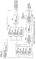
- Fig. 2 is a block diagram showing an example of the image data compensation section 107 illustrated in the control circuit diagram in Fig. 1.
- Fig. 3 is a view showing exemplary images of Y, M and C used for explanations of the present invention.
- Fig. 4 is a view showing image data of Y, M and C corresponding to the exemplary images in Fig. 3.
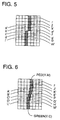
- Fig. 5 is a view showing an example of two-dimensional development of logically processed data which has been provided when the image data of Y, M and C corresponding to the exemplary images in Fig. 3 is subjected to logical processing.
- Fig. 6 is a view showing an example of output provided when the exemplary images in Fig. 3 are subjected to smoothing compensation by the color image processing apparatus of the present invention.
- Fig. 7 is a view showing a reference image pattern, an output pattern corresponding to the reference image pattern, and a pixel position data corresponding to the reference image pattern.
- Fig. 8 is a view showing exemplary images of Y, M and C used for explanations of the present invention.
- Fig. 9 is a view showing image data of Y, M and C corresponding to the exemplary images in Fig. 8.
- Fig. 10 is a view showing an example of two-dimensional development of logically processed data which has been provided when the image data of Y, M and C corresponding to the exemplary images in Fig. 8 is subjected to logical processing.
- Fig. 11 is a view showing an example of output provided when the exemplary images in Fig. 8 are subjected to smoothing compensation by the color image processing apparatus of the present invention.
- Fig. 12 is a view showing another example of output provided when the exemplary images in Fig. 8 are subjected to smoothing compensation by the color image processing apparatus of the present invention.
- Fig. 13 is a view showing another reference image pattern, an output pattern corresponding to the reference image pattern, and a pixel position data corresponding to the reference image pattern.
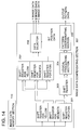
- Fig. 14 is a block diagram showing another example of the image data compensation section 307 used for the color image processing apparatus of the present invention.
- Fig. 1 is a block diagram showing an example of the circuit diagram of a color printer to which an example of the color image processing apparatus of the present invention is applied.
- Print data is sent to the outside interface 104 from the host computer 101, scanner 102 and communication modem 103. After that, the print data is temporarily stored in the data memory section 109, and then sent to the image data memory section 110 by the action of the CPU 105 so that the print data is stored in the image data memory section 110.
- the CPU 105 is operated in accordance with the control program stored in the program ROM 106.
- the image data stored in the image data memory section 110 is sent to the image data compensating section 107.
- the image data is subjected to smoothing processing.
- the image data is outputted to the printing section 112 through the image data output section 111. In this way, printing is conducted in the printing section 112.
- the present invention is applied to a color printer. Accordingly, Y, M and C, which are the three primary colors in a relation of the complementary colors, are used for the image data.
- Fig. 2 is a block diagram showing an example of the image data compensation section 107 illustrated in the control circuit diagram in Fig. 1.
- Fig. 3 is a view showing the examples of original images of the image data sent from the host computer 101, scanner 102 and communication modem 103.
- Fig. 6 is a view showing an example of output provided when the exemplary images in Fig. 3 are subjected to smoothing compensation by the color image processing apparatus of the present invention.
- This image data is successively sent to the shift register 202 in the next stage, and at the same time, the image data is also sent to the shift register 203 through the logical processing section 204.
- the image data of Y, M and C is superimposed in the shift register 203. Then the image data is two-dimensionally developed in the form of logically processed data of pixel unit as illustrated in Fig. 5.
- the aforesaid logically processed data is sent to the pattern discriminating section 205. Then the logically processed data is compared with a plurality of predetermined reference image patterns ((A) to (H) in Fig. 7, and (O) to (V) in Fig. 13) for each pixel.
- the reference image patterns shown by (A) to (H) in Fig. 7 are examples of the patterns used for the smoothing operation with respect to a longitudinally diagonal line.
- the reference image patterns shown by (O) to (V) in Fig. 13 are examples of the patterns used for the smoothing operation with respect to a laterally diagonal line. Both of them are patterns of 7 ⁇ 7 pixel.
- mark ( ⁇ ) represents "there is a pixel”
- mark ( ⁇ ) represents "there is no pixel”
- a vacancy represents "there is no relation to a pixel”.
- a specific pixel (target pixel) in the logically processed data which has been two-dimensionally developed is compared with all the reference image patterns of (A) to (H) in Fig. 7 and (O) to (V) in Fig. 13.
- the output pattern data and the pixel position data are selected according to "there is a pixel" or "there is no pixel" in the target pixel.
- the output pattern data and the pixel position data corresponding to the coincident reference image pattern are selected.
- the target pixel of the logically processed data is latterally shifted by one pixel, and the same comparing operation is performed.
- the target pixel is moved downward by one pixel, and a comparing operation is performed in the lateral direction in the same manner.
- all the logically processed data is processed so that the data can become the target pixel.
- the pattern discriminating section 205 may be composed of a ROM. It may be also composed of a logic circuit.
- an appropriate digital value may be set for the output pattern data with respect to each output pattern of (A') to (H'), (X') and (Y') in Fig. 7, and (O') to (V') in Fig. 13.
- an appropriate digital value may be set for the pixel position data with respect to [CENTER]. [RIGHT], [LEFT], [UPPER] and [LOWER].
- image data for each of Y, M and C is sent to the shift register 202 from the shift register 201.
- the data selector 206 at least image data of Y, M and C corresponding to the target pixel, and image data disposed in the right and left, and upper and lower positions of the image data, can be selected.
- output pattern data corresponding to the output pattern of (A') in Fig. 7, and pixel position data of (A'') in Fig. 7 are selected.
- the image data of Y, M and C according to the right ((e) in Fig. 3) of the image data is selected.
- (g') in Fig. 5 corresponds to (g) in Fig. 3, and (g') is determined to be a target pixel.
- the image data of Y, M and C according to the left ((c) in Fig. 3) of the image data is selected.
- (j') in Fig. 5 corresponds to (j) in Fig. 3, and (j') is determined to be a target pixel.
- the output pattern data and the pixel position data are selected according to "there is a pixel" or “there is no pixel” with respect to (j') in Fig. 5.
- (j') in Fig. 5 represents "there is a pixel”. Therefore, output pattern data corresponding to the output pattern of (Y') in Fig. 7, and pixel position data of (Y'') in Fig. 7, are selected.
- image data of Y, M and C based on the image data ((j) in Fig. 3) is selected.
- (m') in Fig. 5 corresponds to (m) in Fig. 3, so that (m') in Fig. 5 is determined to be a target pixel.
- the output pattern data and the pixel position data are selected according to "there is a pixel" or “there is no pixel” with respect to (m') in Fig. 5.
- (m') in Fig. 5 represents "there is no pixel”. Therefore, output pattern data corresponding to the output pattern of (X') in Fig. 7, and pixel position data of (X'') in Fig. 7, are selected.
- image data of Y, M and C based on the image data ((m) in Fig. 3) is selected.
- a substantial output configuration is determined with respect to the target pixel, and in accordance with the selected pixel position data, the color of the output configuration, that is, the image data of Y, M and C is determined with respect to the target pixel. Then the data is outputted from the data selector 206.
- the output pattern data and the image data of Y, M and C are synchronously outputted from the image data compensation section 107, and printed in the printing section 112 through the image data output section 111.
- the image shown in Fig. 3 is converted into an image subjected to smoothing processing as illustrated in Fig. 6.
- a correlation of the image data of Y, M and C is reflected on the aforesaid processing, so that image tone can be maintained through the smoothing operation.
- the line data of Y, M and C is loaded in the shift register 201.
- the data is two-dimensionally developed in the form of image data of pixel unit for each of Y, M and C.
- the aforesaid image data is subjected to the processing (2) in the logical processing section 204, and only the black region of the image data is two-dimensionally developed as illustrated in Fig. 10.
- the logically processed data developed two-dimensionally as illustrated in Fig. 10 is compared with reference image patterns ((A) to (H) in Fig. 7, and (O) to (V) in Fig. 13) in the pattern discriminating section 205, and the data is subjected to the smoothing processing as described above. In this way, an output image shown in Fig. 11 is provided.
- the line data of Y, M and C is loaded in the shift register 201.
- the data is two-dimensionally developed in the form of image data of pixel unit for each of Y, M and C.
- the aforesaid image data is subjected to the processing (3) in the logical processing section 204, and only the region of the image data which is not black is two-dimensionally developed as illustrated in Fig. 5.
- the logically processed data developed two-dimensionally as illustrated in Fig. 5 is compared with reference image patterns ((A) to (H) in Fig. 7, and (O) to (V) in Fig. 13) in the pattern discriminating section 205, and the data is subjected to the smoothing processing as described above. In this way, an output image shown in Fig. 6 is provided.
- an output image shown in Fig. 12 can be provided in the following manner: The image shown in Fig. 8 is subjected to the logical processing (2) described before, and then the image is further subjected to the logical processing (3) described before.
- the output image shown in Fig. 6 and that shown in Fig. 11 are synthesized in the image data output section 111, the output image shown in Fig. 12 can be provided.
- the image shown in Fig. 8 can be subjected to the smoothing processing so that the image shown in Fig. 6, 11 or 12 can be provided.
- the processing conducted by the logical processing section 204 may be changed over by an original judgment of the CPU. Further, the processing conducted by the logical processing section 204 may be manually changed over by an operator when he operates the operating section 108.
- the output pattern data outputted from the image data compensation section 107 may be outputted as it is, or alternatively the data may be further processed in accordance with the characteristics and function of the image data output section 111.
- smoothing compensation can be performed without affecting the image color.
Landscapes
- Engineering & Computer Science (AREA)
- Physics & Mathematics (AREA)
- General Physics & Mathematics (AREA)
- Theoretical Computer Science (AREA)
- Multimedia (AREA)
- Signal Processing (AREA)
- Computer Hardware Design (AREA)
- General Engineering & Computer Science (AREA)
- Image Processing (AREA)
- Facsimile Image Signal Circuits (AREA)
Abstract
Description
- The present invention relates to a color printer or a color image processing apparatus in which a CRT is used.
- Recently, improved image processing technique of "smoothing compensation" has been adopted to printers. In this case, "smoothing compensation" is defined as a technique in which the configuration of an outputted image is discriminated and a minimum unit forming the outputted image is further fractionalized for providing image compensation.
- This technique has been employed since it is an effective means for monocolor image formation.
- In general, color image data is composed of three pieces of image data resolved into three primary colors. For example, in the case of a CRT, the three colors of red, green and blue are used, and in the case of a color printer, the three primary colors of yellow, magenta and cyan (referred to as Y.M.C hereinafter), which are in a relation of complementary colors, are used.
- When a conventional smoothing compensation is conducted on the color image data resolved into three complimentary colors, the smoothing compensation operation is conducted on each primary color.
- Since smoothing compensation is provided to each primary color in the aforesaid case, a correlation of three primary colors is not reflected on the smoothing operation. Therefore, image tone is deteriorated when smoothing compensation is conducted, which is a problem in the prior art.
- That is, the conventional smoothing compensation is suitable for monochrome image data, however, it is not suitable for color image data resolved into three primary colors.
- The present invention has been achieved to overcome the aforesaid disadvantages of the conventional apparatus. It is an object of the present invention to provide a color image processing apparatus by which smoothing compensation can be conducted on not only monochrome image data but also color image data without deteriorating image tone.
- In order to solve the aforesaid problems, a color image processing apparatus of the present invention includes: a first memory means for storing plural color component data, the unit of which is a pixel; a logical processing means for superimposing each color image data in the plural color component data by a unit of pixel; a second memory means for storing the data processed by the logical processing means; a comparison means for comparing the logically processed data stored in the second memory means with plural predetermined two-dimensional reference image patterns, and also for outputting an output pattern data corresponding to a coincident two-dimensional reference image pattern in the case where the logically processed data stored in the second memory means coincides with one of the plural predetermined two-dimensional reference image patterns, and also for outputting a pixel position data corresponding to the coincident two-dimensional reference image pattern; and a generation means for generating plural color component signals in accordance with the pixel position data.
- An outline of the operation of the present invention will be explained as follows in the case where an image shown in Fig. 3 is stored in the image
data memory section 110 in the form of line data of Y, M and C shown by (A), (B) and (C) in Fig. 4. - Line data of Y, M and C are loaded into the
shift register 201. In theshift register 201, the line data is developed in the form of two-dimensional image data of pixel unit for each of Y, M and C. - The image data is subjected to either of the following (1), (2) and (3) in the
logic processing section 204. - The processing is not necessarily limited to the following three ways, but one way or two ways may be employed.
- In this connection, in the case where a plurality of processing operations are prepared, it is necessary to provide a command setting conducted by a CPU, and also to provide a switching means for switching the processing.

When the logical processing of (1) is performed, the image data of Y, M and C are superimposed.

By the logical processing of (2), the image data of black regions is extracted from the image data of Y, M and C.

By the logical processing of (3), the image data of regions that are not black is extracted from the image data of (Y), (M) and (C). - In this case, (Y) denotes yellow image data, (M) denotes magenta image data, (C) denotes cyan image data, (DATA) denotes image data subjected to logical processing (DATA is referred to as logically processed data, hereinafter.), (+) denotes a logical sum, and (X) denotes a logical product.
- A case in which logical processing of item (1) is performed will be briefly explained as follows.
- Image data of Y, M and C developed two-dimensionally in each
shift register 201 is subjected to logical processing in thelogical processing section 204, and superimposed and developed in theshift register 203 as illustrated in Fig. 5. - The logically processed data which has been developed two-dimensionally is compared with a reference image pattern ((A) to (H) in Fig. 7, and (O) to (V) in Fig. 13) for each pixel of logically processed data.
- The logically processed data and the reference image pattern are compared in the following manner: When a specific pixel of logically processed data developed two-dimensionally (the specific pixel of logically processed data will be referred to as a target pixel, hereinafter) is adjusted at the center of each reference image pattern, it is judged whether or not the logically processed data developed two-dimensionally coincides with the reference image pattern.
- In the case where the logically processed data does not coincide with any reference image pattern as a result of the comparison between the logically processed data developed two-dimensionally and the reference image pattern on the basis of the target pixel, the output pattern is selected in accordance with "there is a pixel" or "there is no pixel" with respect to the target pixel, wherein the case of "there is a pixel" is represented by (X') in Fig. 7, and the case of "there is no pixel" is represented by (Y') in Fig. 7. Therefore, the output pattern data corresponding to the output pattern is outputted from the pattern
discriminating section 205. - In the case where the logically processed data coincides with at least one of the reference image patterns as a result of the comparison between the logically processed data developed two-dimensionally and the reference image pattern on the basis of the target pixel, a predetermined output pattern ((A') to (H') in Fig. 7, and (O') to (V') in Fig. 13) is selected as an output pattern corresponding to the target pixel. Accordingly, output pattern data corresponding to the output pattern is outputted from the pattern
discriminating section 205. - This selecting processing operation is to convert a normal output pattern ((X') or (Y') in Fig. 7) of the logically processed data with respect to the target pixel, into a fractionalized output pattern ((A') to (H') in Fig. 7, and (O') to (V') in Fig. 13). Therefore, this selecting processing operation functions to improve the quality of an outputted image.
- Concurrently when the output pattern is selected in this selecting processing operation, pixel position data illustrated by (A'') to (H'') and (X'') to (Y'') in Fig. 7 and also illustrated by (O'') to (V'') in Fig. 13, is selected in relation to the selection of the output pattern, and the selected pixel position data is outputted from the pattern discriminating section.
- The pixel position data is used for determining the color of the selected output pattern.
- The pixel position data outputted from the pattern
discriminating section 205 is inputted into thedata selector 206. Then thedata selector 206 selects and outputs the image data of Y, M and C in accordance with the inputted pixel position data. - Further, the aforesaid image data of Y, M and C is outputted from the image
data compensating section 107 synchronously with the aforesaid output pattern data. - For example, when the target pixel is (a') shown in Fig. 5, the logically processed data developed in the
shift register 203 coincides with the reference image pattern shown by (A) in Fig. 7. - In other words, when (a') shown in Fig. 5 is adjusted at the center of the reference image pattern of (A) in Fig. 7, a pixel arrangement of the logically processed data in Fig. 5 coincides with the reference image pattern of (A) in Fig. 7.
- In this case, as an output pattern with respect to (a') in Fig. 5 which is a target pixel, (A') in Fig. 7 is selected, and (A'') in Fig. 7 is selected as the pixel position data.
- Since the content of (A'') in Fig. 7 is [RIGHT], when the aforesaid pixel position data is inputted into the
data selector 206, the image data of Y, M and C corresponding to (e') in Fig. 5 which is a pixel on the right of (a') in Fig. 5, is outputted from thedata selector 206. - As described above, the output pattern data corresponding to (A') in Fig. 7, and the image data of Y, M and C corresponding to (e') in Fig. 5, are synchronously outputted from the
image compensating section 107. - In this case, when consideration is given to (e) in Fig. 3, since the image data of Y, M and C corresponding to (e') in Fig. 5 is only (Y) and (M), only (Y) and (M) are outputted from the
data selector 206. - As a result of the foregoing processing, an image, the output pattern of which is (A') in Fig. 7 and the color of which is RED (Y.M), is expressed in the portion (a) in Fig. 3 as illustrated in (A') in Fig. 6.
- When all the image data is subjected to the aforesaid processing, the image shown in Fig. 3 is outputted in the form of an image shown in Fig. 6. That is, smoothing compensation is conducted.
- Fig. 1 is a block diagram showing an example of the circuit diagram of a color printer to which an example of the color image processing apparatus of the present invention is applied.
- Fig. 2 is a block diagram showing an example of the image
data compensation section 107 illustrated in the control circuit diagram in Fig. 1. - Fig. 3 is a view showing exemplary images of Y, M and C used for explanations of the present invention.
- Fig. 4 is a view showing image data of Y, M and C corresponding to the exemplary images in Fig. 3.
- Fig. 5 is a view showing an example of two-dimensional development of logically processed data which has been provided when the image data of Y, M and C corresponding to the exemplary images in Fig. 3 is subjected to logical processing.
- Fig. 6 is a view showing an example of output provided when the exemplary images in Fig. 3 are subjected to smoothing compensation by the color image processing apparatus of the present invention.
- Fig. 7 is a view showing a reference image pattern, an output pattern corresponding to the reference image pattern, and a pixel position data corresponding to the reference image pattern.
- Fig. 8 is a view showing exemplary images of Y, M and C used for explanations of the present invention.
- Fig. 9 is a view showing image data of Y, M and C corresponding to the exemplary images in Fig. 8.
- Fig. 10 is a view showing an example of two-dimensional development of logically processed data which has been provided when the image data of Y, M and C corresponding to the exemplary images in Fig. 8 is subjected to logical processing.
- Fig. 11 is a view showing an example of output provided when the exemplary images in Fig. 8 are subjected to smoothing compensation by the color image processing apparatus of the present invention.
- Fig. 12 is a view showing another example of output provided when the exemplary images in Fig. 8 are subjected to smoothing compensation by the color image processing apparatus of the present invention.
- Fig. 13 is a view showing another reference image pattern, an output pattern corresponding to the reference image pattern, and a pixel position data corresponding to the reference image pattern.
- Fig. 14 is a block diagram showing another example of the image
data compensation section 307 used for the color image processing apparatus of the present invention. - With reference to the accompanying drawings, an example of the color image processing apparatus of the present invention will be explained as follows in the case where the apparatus is applied to a color printer.
- Fig. 1 is a block diagram showing an example of the circuit diagram of a color printer to which an example of the color image processing apparatus of the present invention is applied.
- Print data is sent to the
outside interface 104 from thehost computer 101,scanner 102 andcommunication modem 103. After that, the print data is temporarily stored in thedata memory section 109, and then sent to the imagedata memory section 110 by the action of theCPU 105 so that the print data is stored in the imagedata memory section 110. - In this case, the
CPU 105 is operated in accordance with the control program stored in theprogram ROM 106. - The image data stored in the image
data memory section 110 is sent to the imagedata compensating section 107. In the imagedata compensating section 107, the image data is subjected to smoothing processing. Then, the image data is outputted to theprinting section 112 through the imagedata output section 111. In this way, printing is conducted in theprinting section 112. - In this case, the present invention is applied to a color printer. Accordingly, Y, M and C, which are the three primary colors in a relation of the complementary colors, are used for the image data.
- Fig. 2 is a block diagram showing an example of the image
data compensation section 107 illustrated in the control circuit diagram in Fig. 1. - Fig. 3 is a view showing the examples of original images of the image data sent from the
host computer 101,scanner 102 andcommunication modem 103. Fig. 6 is a view showing an example of output provided when the exemplary images in Fig. 3 are subjected to smoothing compensation by the color image processing apparatus of the present invention. - In the case where an image shown in Fig. 3 is stored in the image
data memory section 110 in the form of line data of Y, M and C as illustrated by (A), (B) and (C) in Fig. 4, the line data of Y, M and C is loaded in theshift register 201. Then, in theshift register 201, the line data is developed in the form of two-dimensional image data of pixel unit for each of Y, M and C. - This image data is successively sent to the
shift register 202 in the next stage, and at the same time, the image data is also sent to theshift register 203 through thelogical processing section 204. - The following are the explanations in the case where the logical processing conducted in the
logical processing section 204 is:

- In other words, the following are the explanations in the case where the image data of Y, M and C is superimposed.
- In this case, the image data of Y, M and C is superimposed in the
shift register 203. Then the image data is two-dimensionally developed in the form of logically processed data of pixel unit as illustrated in Fig. 5. - The aforesaid logically processed data is sent to the
pattern discriminating section 205. Then the logically processed data is compared with a plurality of predetermined reference image patterns ((A) to (H) in Fig. 7, and (O) to (V) in Fig. 13) for each pixel. - The reference image patterns shown by (A) to (H) in Fig. 7 are examples of the patterns used for the smoothing operation with respect to a longitudinally diagonal line. The reference image patterns shown by (O) to (V) in Fig. 13 are examples of the patterns used for the smoothing operation with respect to a laterally diagonal line. Both of them are patterns of 7 × 7 pixel.
- In (A) to (H) shown in Fig. 7 and (O) to (V) shown in Fig. 13, mark (●) represents "there is a pixel", and mark (○) represents "there is no pixel", and a vacancy represents "there is no relation to a pixel".
- A comparison is made between the center of each reference image pattern (shown in Fig. 7) and a specific pixel (referred to as a target pixel hereinafter) in each logically processed data. Then, it is judged whether or not the logically processed data pattern which has been two-dimensionally developed coincides with any of the reference patterns.
- A specific comparison method will be explained as follows.
- A specific pixel (target pixel) in the logically processed data which has been two-dimensionally developed is compared with all the reference image patterns of (A) to (H) in Fig. 7 and (O) to (V) in Fig. 13. In the case where the target pixel does not coincide with any of the reference image patterns, the output pattern data and the pixel position data are selected according to "there is a pixel" or "there is no pixel" in the target pixel.
- When the target pixel coincides with one of the reference image patterns of (A) to (H) in Fig. 7 and (O) to (V) in Fig. 13, the output pattern data and the pixel position data corresponding to the coincident reference image pattern are selected.
- After one target pixel has been compared with the reference image patterns, the target pixel of the logically processed data is latterally shifted by one pixel, and the same comparing operation is performed. When one line of shifting and comparing operation has been completed, the target pixel is moved downward by one pixel, and a comparing operation is performed in the lateral direction in the same manner.
- In the aforesaid manner, all the logically processed data is compared with the reference image patterns, and the output pattern data and the pixel position data are selected.
- In other words, all the logically processed data is processed so that the data can become the target pixel.
- In the case where the logically processed data and the reference image pattern are compared, it is necessary to provide 7 × 7 bits of logically processed data, wherein the target pixel is disposed at the center of the data. Therefore, the aforesaid 7 × 7 bits of logically processed data is sent to the
pattern discriminating section 205 through theshift register 203. - In this connection, the
pattern discriminating section 205 may be composed of a ROM. It may be also composed of a logic circuit. - Although it is not clearly shown in the drawings, an appropriate digital value may be set for the output pattern data with respect to each output pattern of (A') to (H'), (X') and (Y') in Fig. 7, and (O') to (V') in Fig. 13.
- In the same manner, an appropriate digital value may be set for the pixel position data with respect to [CENTER]. [RIGHT], [LEFT], [UPPER] and [LOWER].
- As described above, image data for each of Y, M and C is sent to the
shift register 202 from theshift register 201. In thedata selector 206, at least image data of Y, M and C corresponding to the target pixel, and image data disposed in the right and left, and upper and lower positions of the image data, can be selected. - There is shown how (a) in Fig. 3 is processed. In this case, (a') in Fig. 5 corresponds to (a) in Fig. 3, and (a') is determined to be a target pixel.
- When a comparison is made while the centers of all reference image patterns are adjusted at the target pixel, the provided pattern coincides with the reference image pattern of (A) in Fig. 7.
- Accordingly, output pattern data corresponding to the output pattern of (A') in Fig. 7, and pixel position data of (A'') in Fig. 7 are selected.
- Since the content of the pixel position data is [RIGHT], the image data of Y, M and C according to the right ((e) in Fig. 3) of the image data is selected.
- That is, when the pixel position data is inputted into the
data selector 206, only image data of (Y) and (M) is outputted from thedata selector 206. - Due to the foregoing, (a) in Fig. 3 is processed as shown by (A') in Fig. 6, and then the processed data is outputted.
- Next, there is shown how (g) in Fig. 3 is processed.
- In this case, (g') in Fig. 5 corresponds to (g) in Fig. 3, and (g') is determined to be a target pixel.
- When a comparison is made while the centers of all the reference image patterns are adjusted at the target pixel, the provided pattern coincides with the reference image pattern of (G) in Fig. 7.
- Consequently, output pattern data corresponding to the output pattern of (G') in Fig. 7, and pixel position data of (G'') in Fig. 7, are selected.
- Since the content of the pixel position data is [LEFT], the image data of Y, M and C according to the left ((c) in Fig. 3) of the image data is selected.
- That is, when the pixel position data is inputted into the
data selector 206, only image data of (Y) and (C) is outputted from thedata selector 206. - Due to the foregoing, (g) in Fig. 3 is processed as shown by (G') in Fig. 6, and then the processed data is outputted.
- Next, there is shown how (j) in Fig. 3 is processed.
- In this case, (j') in Fig. 5 corresponds to (j) in Fig. 3, and (j') is determined to be a target pixel.
- Even when a comparison is made while the centers of all the reference image patterns are adjusted at the target pixel, the provided pattern does not coincide with any of the reference patterns. Therefore, the output pattern data and the pixel position data are selected according to "there is a pixel" or "there is no pixel" with respect to (j') in Fig. 5.
- In this case, (j') in Fig. 5 represents "there is a pixel". Therefore, output pattern data corresponding to the output pattern of (Y') in Fig. 7, and pixel position data of (Y'') in Fig. 7, are selected.
- Since the content of the pixel position data is [CENTER], image data of Y, M and C based on the image data ((j) in Fig. 3) is selected.
- That is, when the pixel position data is inputted into the
data selector 206, only the image data of (Y) and (M) is outputted from thedata selector 206. - Due to the foregoing, (j) in Fig. 3 is processed in the manner of (j') in Fig. 6 and outputted.
- Next, there is shown how (m) in Fig. 3 is processed.
- In this case, (m') in Fig. 5 corresponds to (m) in Fig. 3, so that (m') in Fig. 5 is determined to be a target pixel.
- Even when a comparison is made while the centers of all the reference image patterns are adjusted at the target pixel, the provided pattern does not coincide with any of the reference patterns. Therefore, the output pattern data and the pixel position data are selected according to "there is a pixel" or "there is no pixel" with respect to (m') in Fig. 5.
- In this case, (m') in Fig. 5 represents "there is no pixel". Therefore, output pattern data corresponding to the output pattern of (X') in Fig. 7, and pixel position data of (X'') in Fig. 7, are selected.
- Since the content of the pixel position data is [CENTER], image data of Y, M and C based on the image data ((m) in Fig. 3) is selected.
- That is, when the pixel position data is inputted into the
data selector 206, no image data is outputted from thedata selector 206. - Accordingly, as illustrated by (M') in Fig. 6, (m) in Fig. 3 outputs no image.
- In the same manner, (b) in Fig. 3 outputs like (B') in Fig. 6, (c) in Fig. 3 outputs like (C') in Fig. 6, (d) in Fig. 3 outputs like (D') in Fig. 6, (e) in Fig. 3 outputs like (E') in Fig. 6, (f) in Fig. 3 outputs like (F') in fig. 6, (h) in Fig. 3 outputs like (H') in Fig. 6, (i) in Fig. 3 outputs like (I') in Fig. 6, (k) in Fig. 6 outputs like (K') in Fig. 6, and (l) in Fig. 3 outputs like (L') in Fig. 6.
- As described above, in accordance with the selected output pattern data, a substantial output configuration is determined with respect to the target pixel, and in accordance with the selected pixel position data, the color of the output configuration, that is, the image data of Y, M and C is determined with respect to the target pixel. Then the data is outputted from the
data selector 206. - The output pattern data and the image data of Y, M and C are synchronously outputted from the image
data compensation section 107, and printed in theprinting section 112 through the imagedata output section 111. - As a result of the foregoing processing operation, the image shown in Fig. 3 is converted into an image subjected to smoothing processing as illustrated in Fig. 6.
- A correlation of the image data of Y, M and C is reflected on the aforesaid processing, so that image tone can be maintained through the smoothing operation.
- The following are the explanations in the case where the logical processing conducted in the
logical processing section 204 is:

- In other words, the following are the explanations in the case where a black region is extracted from the image data of Y, M and C, and only the black region is subjected to the smoothing compensation processing.
- In the case where the image shown in Fig. 8 is stored by the
image data memory 110 in the form of line data of Y, M and C as illustrated in (A), (B) and (C) of Fig. 9, the line data of Y, M and C is loaded in theshift register 201. In theshift register 201, the data is two-dimensionally developed in the form of image data of pixel unit for each of Y, M and C. - The aforesaid image data is subjected to the processing (2) in the
logical processing section 204, and only the black region of the image data is two-dimensionally developed as illustrated in Fig. 10. - The logically processed data developed two-dimensionally as illustrated in Fig. 10 is compared with reference image patterns ((A) to (H) in Fig. 7, and (O) to (V) in Fig. 13) in the
pattern discriminating section 205, and the data is subjected to the smoothing processing as described above. In this way, an output image shown in Fig. 11 is provided. - The following are the explanations in the case where the logical processing conducted in the
logical processing section 204 is:

In other words, the following are the explanations in the case where a region which is not black is extracted from the image data of Y, M and C, and only the extracted region is subjected to the smoothing compensation processing. - In the case where the image shown in Fig. 8 is stored by the
image data memory 110 in the form of line data of Y, M and C as illustrated in (A), (B) and (C) of Fig. 9, the line data of Y, M and C is loaded in theshift register 201. In theshift register 201, the data is two-dimensionally developed in the form of image data of pixel unit for each of Y, M and C. - The aforesaid image data is subjected to the processing (3) in the
logical processing section 204, and only the region of the image data which is not black is two-dimensionally developed as illustrated in Fig. 5. - The logically processed data developed two-dimensionally as illustrated in Fig. 5 is compared with reference image patterns ((A) to (H) in Fig. 7, and (O) to (V) in Fig. 13) in the
pattern discriminating section 205, and the data is subjected to the smoothing processing as described above. In this way, an output image shown in Fig. 6 is provided. - In this connection, an output image shown in Fig. 12 can be provided in the following manner:
The image shown in Fig. 8 is subjected to the logical processing (2) described before, and then the image is further subjected to the logical processing (3) described before. When the output image shown in Fig. 6 and that shown in Fig. 11 are synthesized in the imagedata output section 111, the output image shown in Fig. 12 can be provided. - As described above, when the processing conducted by the
logical processing section 204 is changed over, the image shown in Fig. 8 can be subjected to the smoothing processing so that the image shown in Fig. 6, 11 or 12 can be provided. - The processing conducted by the
logical processing section 204 may be changed over by an original judgment of the CPU. Further, the processing conducted by thelogical processing section 204 may be manually changed over by an operator when he operates theoperating section 108. - In the above explanations, the case of longitudinally diagonal lines which are positioned from the upper right to the lower left is taken for an example. Since is provided a reference image pattern obtained when (A) to (H) in Fig. 7 are laterally reversed, longitudinally diagonal lines positioned from the upper left to the lower right can be also subjected to the smoothing processing in the same manner.
- Moreover, in the color image processing apparatus of the present invention, since reference image patterns of (O) to (V) in Fig. 13 are provided, the same smoothing processing can be conducted on laterally diagonal lines positioned from the upper left to the lower right.
- In the same manner, since is provided a reference image pattern obtained when (O) to (V) in Fig. 13 are laterally reversed, laterally diagonal lines positioned from the upper right to the lower left can be also subjected to the smoothing processing.
- Due to the foregoing, color images of longitudinally and laterally diagonal lines can be subjected to the smoothing compensation. Therefore, according to the color image processing apparatus of the present invention, characters composed of various diagonal lines can be subjected to the smoothing compensation.
- In this connection, the output pattern data outputted from the image
data compensation section 107 may be outputted as it is, or alternatively the data may be further processed in accordance with the characteristics and function of the imagedata output section 111. - In the above explanations, only a system is described in which: as illustrated in Fig. 2, the logically processed data subjected to the processing in the logically processing
section 204 is two-dimensionally developed in theshift register 203 as illustrated in Fig. 5; and then the data is compared with the reference image patterns in thepattern discriminating section 205. However, as illustrated in Fig. 14, it is possible to conduct the smoothing compensating operation on the data in a differentimage compensating section 307 in the same manner. - Like parts in Fig. 14 are identified by the same reference character.
- In Fig. 14, the logically processed data outputted from the logically processing
section 304 is directly inputted into thepattern discriminating section 205. - An example in which the color image processing apparatus of the present invention is used is explained above. When image data is expressed by R, G and B, the same smoothing processing can be applied to a displaying apparatus such as CRT.
- As explained above, according to the color image processing apparatus of the present invention, smoothing compensation can be performed without affecting the image color.
Claims (5)
- An image processing apparatus for smoothing an image, comprising:
a first memory means for storing an image data which includes color component data of yellow, magenta, and cyan for each pixel thereof;
a logical processing means for superimposing said color component data pixel by pixel, and said logical processing means for generating a processed image data;
a comparison means for comparing said processed image data with a plurality of predetermined two-dimensional reference image patterns, and for selecting one of said plurality of predetermined two-dimensional reference image patterns which coincides with said processed image data so that pixel position data, corresponding to selected one of said plurality of predetermined two-dimensional reference image patterns, is generated; and
a generation means for generating color component signals of yellow, magenta, and cyan according to said pixel position data. - The image processing apparatus of claim 1, further comprising:
a second memory means for storing said processed image data;
wherein said comparison means compares said processed image data, stored in said second memory means, with said plurality of predetermined two-dimensional reference image patterns. - The image processing apparatus of claim 1, wherein said logical processing means extracting black pixel region from said image data stored in said first memory means.
- The image processing apparatus of claim 1, wherein said logical processing means extracting a region other than a black pixel region from said image data stored in said first memory means.
- The image processing apparatus of claim 1, wherein said predetermined two-dimensional reference image patters include a first set for processing said image data in vertical direction and a second set for processing said image data in horizontal direction.
Applications Claiming Priority (3)
| Application Number | Priority Date | Filing Date | Title |
|---|---|---|---|
| JP342640/92 | 1992-12-22 | ||
| JP34264092 | 1992-12-22 | ||
| JP34264092 | 1992-12-22 |
Publications (3)
| Publication Number | Publication Date |
|---|---|
| EP0603833A2 true EP0603833A2 (en) | 1994-06-29 |
| EP0603833A3 EP0603833A3 (en) | 1997-11-12 |
| EP0603833B1 EP0603833B1 (en) | 1999-06-30 |
Family
ID=18355341
Family Applications (1)
| Application Number | Title | Priority Date | Filing Date |
|---|---|---|---|
| EP93120630A Expired - Lifetime EP0603833B1 (en) | 1992-12-22 | 1993-12-21 | Color image processing apparatus for smoothing compensation of an image |
Country Status (3)
| Country | Link |
|---|---|
| US (1) | US5774636A (en) |
| EP (1) | EP0603833B1 (en) |
| DE (1) | DE69325497T2 (en) |
Cited By (1)
| Publication number | Priority date | Publication date | Assignee | Title |
|---|---|---|---|---|
| EP0863458A3 (en) * | 1997-03-05 | 2002-03-13 | Canon Kabushiki Kaisha | Printing system, and printing control method and apparatus |
Families Citing this family (4)
| Publication number | Priority date | Publication date | Assignee | Title |
|---|---|---|---|---|
| JP4134456B2 (en) * | 1999-09-17 | 2008-08-20 | 富士ゼロックス株式会社 | Multicolor image forming apparatus |
| US7116821B2 (en) * | 2002-03-25 | 2006-10-03 | Lexmark International, Inc. | Color trapping for an image forming apparatus |
| JP4194433B2 (en) * | 2003-07-07 | 2008-12-10 | キヤノン株式会社 | Likelihood calculation apparatus and method |
| CN106898291B (en) * | 2017-04-28 | 2019-08-02 | 武汉华星光电技术有限公司 | The driving method and driving device of display panel |
Family Cites Families (16)
| Publication number | Priority date | Publication date | Assignee | Title |
|---|---|---|---|---|
| US4285004A (en) * | 1980-02-25 | 1981-08-18 | Ampex Corporation | Total raster error correction apparatus and method for the automatic set up of television cameras and the like |
| JPS5846341A (en) * | 1981-09-16 | 1983-03-17 | Dainippon Screen Mfg Co Ltd | Converting method for reproduced color in displaying of reproduced color of multicolor printed matter |
| JPS59205876A (en) * | 1983-05-10 | 1984-11-21 | Canon Inc | Method and apparatus for processing color picture |
| US4730185A (en) * | 1984-07-06 | 1988-03-08 | Tektronix, Inc. | Graphics display method and apparatus for color dithering |
| JPH0621769B2 (en) * | 1985-12-13 | 1994-03-23 | 大日本スクリ−ン製造株式会社 | Pattern defect detection method and device |
| DE3629195A1 (en) * | 1986-01-14 | 1987-07-23 | Canon Kk | COLOR IMAGE PROCESSING DEVICE |
| US5005139A (en) * | 1988-08-16 | 1991-04-02 | Hewlett-Packard Company | Piece-wise print image enhancement for dot matrix printers |
| US5208663A (en) * | 1989-03-22 | 1993-05-04 | Konica Corporation | Color image processing apparatus provided with an image discrimination means |
| JPH0372778A (en) * | 1989-08-11 | 1991-03-27 | Fuji Xerox Co Ltd | Area identification system for picture processing unit |
| US5029108A (en) * | 1990-09-24 | 1991-07-02 | Destiny Technology Corporation | Edge enhancement method and apparatus for dot matrix devices |
| JP3110746B2 (en) * | 1990-10-09 | 2000-11-20 | キヤノン株式会社 | Image processing method |
| US5438437A (en) * | 1991-10-17 | 1995-08-01 | Konica Corporation | Image forming apparatus with exposure, size, and position correction for pixels |
| US5168552A (en) * | 1991-10-29 | 1992-12-01 | Hewlett-Packard Company | Color separation in ink jet color graphics printing |
| US5313291A (en) * | 1991-11-25 | 1994-05-17 | Xerox Corporation | Method for matching color prints to color images on a monitor screen |
| US5317425A (en) * | 1992-02-10 | 1994-05-31 | Eastman Kodak Company | Technique for use in conjunction with an imaging system for providing an appearance match between two images and for calibrating the system thereto |
| US5396584A (en) * | 1992-05-29 | 1995-03-07 | Destiny Technology Corporation | Multi-bit image edge enhancement method and apparatus |
-
1993
- 1993-12-21 EP EP93120630A patent/EP0603833B1/en not_active Expired - Lifetime
- 1993-12-21 DE DE69325497T patent/DE69325497T2/en not_active Expired - Fee Related
-
1996
- 1996-08-14 US US08/696,470 patent/US5774636A/en not_active Expired - Fee Related
Cited By (2)
| Publication number | Priority date | Publication date | Assignee | Title |
|---|---|---|---|---|
| EP0863458A3 (en) * | 1997-03-05 | 2002-03-13 | Canon Kabushiki Kaisha | Printing system, and printing control method and apparatus |
| US7099025B2 (en) | 1997-03-05 | 2006-08-29 | Canon Kabushiki Kaisha | Printing system, printing control method and apparatus printing data in accordance with updated condition information |
Also Published As
| Publication number | Publication date |
|---|---|
| EP0603833A3 (en) | 1997-11-12 |
| DE69325497T2 (en) | 2000-01-05 |
| EP0603833B1 (en) | 1999-06-30 |
| DE69325497D1 (en) | 1999-08-05 |
| US5774636A (en) | 1998-06-30 |
Similar Documents
| Publication | Publication Date | Title |
|---|---|---|
| DE3486434T2 (en) | Imaging device | |
| US6927877B2 (en) | Image processing method and apparatus for converting colors in a color image | |
| US5659770A (en) | Text/image processing apparatus determining synthesis format | |
| EP1073260B1 (en) | Image processing device, image forming device incorporating the same, and storage medium for storing program used thereby | |
| US5701401A (en) | Printing black and white reproducible color documents | |
| US5105267A (en) | Color conversion apparatus | |
| JP2978325B2 (en) | Image processing method and printer interface realizing the same | |
| US5565907A (en) | Image forming apparatus capable of producing high quality halftone images | |
| US5596355A (en) | Color ink jet recording apparatus capable of high-quality printing of black portions | |
| US5920645A (en) | Image forming apparatus and method which performs an under color removal process using image signals obtained during a scanning operation | |
| JPH08116464A (en) | Colored picture processing and picture processor | |
| JPH0746415A (en) | Color image processing method | |
| US6842268B1 (en) | Printing of digital color images with locally adjusted half-toning | |
| US6259536B1 (en) | Color printing yielding a background dependent black image (i.e. intelligent black) | |
| EP0603833B1 (en) | Color image processing apparatus for smoothing compensation of an image | |
| US5475496A (en) | Image processing apparatus for binarizing multi-value image data | |
| US6275302B1 (en) | Color printing yielding a background dependent neutral gray image (i.e. intelligent gray) | |
| EP0817122B1 (en) | Filter and raster operations | |
| US5361141A (en) | Image processor | |
| JPH07256972A (en) | Printer device | |
| EP0537887B1 (en) | Method and apparatus for simulating the reproduction of an image represented by screened colour separation data | |
| JP3412847B2 (en) | Image processing apparatus and method | |
| JP3155541B2 (en) | Image forming apparatus and control method thereof | |
| EP0587239B1 (en) | Superimposition of images in a copier or printer | |
| US5388195A (en) | Image processing system with editing area correcting function |
Legal Events
| Date | Code | Title | Description |
|---|---|---|---|
| PUAI | Public reference made under article 153(3) epc to a published international application that has entered the european phase |
Free format text: ORIGINAL CODE: 0009012 |
|
| AK | Designated contracting states |
Kind code of ref document: A2 Designated state(s): DE GB |
|
| PUAL | Search report despatched |
Free format text: ORIGINAL CODE: 0009013 |
|
| AK | Designated contracting states |
Kind code of ref document: A3 Designated state(s): DE FR GB IT NL |
|
| 17P | Request for examination filed |
Effective date: 19980504 |
|
| GRAG | Despatch of communication of intention to grant |
Free format text: ORIGINAL CODE: EPIDOS AGRA |
|
| 17Q | First examination report despatched |
Effective date: 19980916 |
|
| GRAG | Despatch of communication of intention to grant |
Free format text: ORIGINAL CODE: EPIDOS AGRA |
|
| GRAH | Despatch of communication of intention to grant a patent |
Free format text: ORIGINAL CODE: EPIDOS IGRA |
|
| RBV | Designated contracting states (corrected) |
Designated state(s): DE GB |
|
| GRAH | Despatch of communication of intention to grant a patent |
Free format text: ORIGINAL CODE: EPIDOS IGRA |
|
| GRAA | (expected) grant |
Free format text: ORIGINAL CODE: 0009210 |
|
| AK | Designated contracting states |
Kind code of ref document: B1 Designated state(s): DE GB |
|
| REF | Corresponds to: |
Ref document number: 69325497 Country of ref document: DE Date of ref document: 19990805 |
|
| PLBE | No opposition filed within time limit |
Free format text: ORIGINAL CODE: 0009261 |
|
| STAA | Information on the status of an ep patent application or granted ep patent |
Free format text: STATUS: NO OPPOSITION FILED WITHIN TIME LIMIT |
|
| 26N | No opposition filed | ||
| PGFP | Annual fee paid to national office [announced via postgrant information from national office to epo] |
Ref country code: DE Payment date: 20001211 Year of fee payment: 8 |
|
| PGFP | Annual fee paid to national office [announced via postgrant information from national office to epo] |
Ref country code: GB Payment date: 20001220 Year of fee payment: 8 |
|
| PG25 | Lapsed in a contracting state [announced via postgrant information from national office to epo] |
Ref country code: GB Free format text: LAPSE BECAUSE OF NON-PAYMENT OF DUE FEES Effective date: 20011221 |
|
| REG | Reference to a national code |
Ref country code: GB Ref legal event code: IF02 |
|
| PG25 | Lapsed in a contracting state [announced via postgrant information from national office to epo] |
Ref country code: DE Free format text: LAPSE BECAUSE OF NON-PAYMENT OF DUE FEES Effective date: 20020702 |
|
| GBPC | Gb: european patent ceased through non-payment of renewal fee |
Effective date: 20011221 |