EP0607711A1 - Electricity meter with variable gain sigma-delta converter - Google Patents
Electricity meter with variable gain sigma-delta converter Download PDFInfo
- Publication number
- EP0607711A1 EP0607711A1 EP93400129A EP93400129A EP0607711A1 EP 0607711 A1 EP0607711 A1 EP 0607711A1 EP 93400129 A EP93400129 A EP 93400129A EP 93400129 A EP93400129 A EP 93400129A EP 0607711 A1 EP0607711 A1 EP 0607711A1
- Authority
- EP
- European Patent Office
- Prior art keywords
- counter
- sigma
- output
- metering device
- gain
- Prior art date
- Legal status (The legal status is an assumption and is not a legal conclusion. Google has not performed a legal analysis and makes no representation as to the accuracy of the status listed.)
- Granted
Links
Images
Classifications
-
- G—PHYSICS
- G01—MEASURING; TESTING
- G01R—MEASURING ELECTRIC VARIABLES; MEASURING MAGNETIC VARIABLES
- G01R21/00—Arrangements for measuring electric power or power factor
- G01R21/133—Arrangements for measuring electric power or power factor by using digital technique
-
- G—PHYSICS
- G06—COMPUTING OR CALCULATING; COUNTING
- G06F—ELECTRIC DIGITAL DATA PROCESSING
- G06F7/00—Methods or arrangements for processing data by operating upon the order or content of the data handled
- G06F7/60—Methods or arrangements for performing computations using a digital non-denominational number representation, i.e. number representation without radix; Computing devices using combinations of denominational and non-denominational quantity representations, e.g. using difunction pulse trains, STEELE computers, phase computers
- G06F7/602—Methods or arrangements for performing computations using a digital non-denominational number representation, i.e. number representation without radix; Computing devices using combinations of denominational and non-denominational quantity representations, e.g. using difunction pulse trains, STEELE computers, phase computers using delta-sigma sequences
-
- G—PHYSICS
- G06—COMPUTING OR CALCULATING; COUNTING
- G06G—ANALOGUE COMPUTERS
- G06G7/00—Devices in which the computing operation is performed by varying electric or magnetic quantities
- G06G7/12—Arrangements for performing computing operations, e.g. operational amplifiers specially adapted therefor
- G06G7/16—Arrangements for performing computing operations, e.g. operational amplifiers specially adapted therefor for multiplication or division
- G06G7/161—Arrangements for performing computing operations, e.g. operational amplifiers specially adapted therefor for multiplication or division with pulse modulation, e.g. modulation of amplitude, width, frequency, phase or form
-
- G—PHYSICS
- G06—COMPUTING OR CALCULATING; COUNTING
- G06J—HYBRID COMPUTING ARRANGEMENTS
- G06J1/00—Hybrid computing arrangements
Definitions
- the present invention relates to an electricity metering device including at least one sigma-delta converter adapted to output a series of digital pulses, a digital counter means for summing the output of the sigma-delta converter and a signalling means to deliver an output signal when the sum reaches a predetermined value.
- Sigma-delta converters are well-known analogue to digital converters, in which an analogue input voltage is summed with a larger reference voltage, the sum being integrated and the running total of the integrator being fed to a clocked comparator which produces a positive or negative output depending on the results of the comparison.
- the positive or negative output of the comparator is fed back to control the polarity of the reference voltage, the polarity being controlled to tend to bring the charge in the integrator towards zero.
- the clocked output of the comparator over a period of time is thus a series of digital pulses of +1 or -1, in which the magnitude of the input voltage is represented by the difference between the number of positive comparator output pulses and the number of negative comparator output pulses, i.e.
- the series of output of pulses of the sigma-delta may then be summed, by an integrator or by an up/down counter, in order to arrive at the digital value corresponding to the input voltage.
- Combined sigma-delta devices are also known (see FR 2 570 854) in which a first signal is fed to a first sigma-delta converter and a second signal to a second sigma-delta converter, the polarity of the second input signal being controlled according to the pulsed output of the first sigma-delta converter.
- the output of the second sigma-delta converter then represents the product of the first and second signals.
- Such sigma-delta circuits find a particular application in the field of the electricity metering, where the voltage of the power supply and/or the value of current taken, as represented by a voltage across a shunt for example, may be converted into digital signals.
- the combination sigma-delta converter discussed above is particularly useful in metering systems as voltage and current signals may be fed to the first and second converters respectively, the output of the second converter representing the product of the signals, i.e. the energy being taken.
- the metering device further comprises a means for digitally adjusting the gain of the sigma-delta converter comprising a programmable digital memory means adapted to store a parameter representing the gain of the metering device, the value of the parameter being externally programmable, and a digital logic means for logically combining the gain parameter with the digital sum stored in the counter means to determine the number of pulses required before the predetermined value is reached and an output pulse delivered.
- a means for digitally adjusting the gain of the sigma-delta converter comprising a programmable digital memory means adapted to store a parameter representing the gain of the metering device, the value of the parameter being externally programmable, and a digital logic means for logically combining the gain parameter with the digital sum stored in the counter means to determine the number of pulses required before the predetermined value is reached and an output pulse delivered.
- the programmable memory means may be a non-volatile memory and may comprise a simple shift register which stores a digital value representing the gain. Once set, the gain of the meter will be fixed unless reprogramming is required at any time during the life of the meter.
- the present invention also gives rise to the advantage that a basic meter design including fixed values of components may be used in a variety of applications to measure a wide range of current and voltage values through selection of the desired values of gain of the meter.
- the gain of each converter may be adjustable by means of an associated programmable memory means and logic means as described above.
- the invention further extends to a metering device comprising a combination of sigma-delta devices operating to give a value representative of the multiplication of the input signals and in which the gain of the final sigma-delta converter of the combination which produces an output representative of the energy or power of the metered supply is adjustable by means of an associated programmable digital memory means and logic means.
- the output signal from the signalling means may further be supplied to an additional counter means to control a meter output display.
- the counter means and signalling means comprise a counter adapted to give an output signal when the counter reaches a fixed predetermined value (such as its maximum value) and in which the gain parameter is a numerical value added by the logic means to the counter in addition to the pulses from the sigma-delta converter.
- the value of an input signal to the sigma-delta converter is represented by the difference between the number of up and down pulses from the converter, i.e. N+ - N ⁇ .
- the counter counts the number of positive pulses (or negative) or the difference between the two, rather than the ratio between the two. Simple addition of a numerical value will thus have a linear effect on the gain of the converter for all magnitudes of input signals.
- the logic means and signalling means may comprise a comparator adapted to compare the value of the gain parameter with the value of the sum in the counter means and to deliver an output signal when the two values are equal.
- the number of positive or negative pulses represents directly the magnitude of the input signal and changing the value of the gain parameter to change the count at which an output signal is delivered will give rise to a linear change in gain across all magnitudes of the input signal.
- the digital counter means for summing the sigma-delta pulses may comprise any suitable counter, such as a simple up counter, in which the sum in the counter represents the number of up pulses only, an up-down binary counter, a counter operating in a non-binary base etc.
- the overall polarity of pulses output from the sigma-delta converter may reflect the overall polarity of the input signal or signals (either directly or inversely) such that, in some instances, the majority of pulses supplied will be positive whilst, in other instances, the pulses supplied will be largely negative.
- the output of the sigma-delta will then switch from a majority of positive pulses to a majority of negative pulses, according to the mode of operation. This will affect the operation of the counter which, typically, comprises a simple up-down binary counter which can count up from a value 000...000 to 111...111 or down from a value 111...111 to 000...000 depending on the polarity of the pulses.
- the invention may then further comprise means for compensating for the polarity of pulses from the sigma-delta converter.
- the counter may comprise a binary up-down counter and the device may further comprise means for supplying the binary complement of the gain parameter to the comparator.
- the gain parameter is set to 101 for a positive count, it will take 5 positive pulses for the counter to reach 101 from 000 and for the comparator to output a signal.
- the complement of 101 is supplied, that is 010. In such operation, the counter will start from 111 and, again, it will take 5 negative pulses to reach 010 from 111.
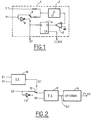
- a sigma-delta converter 1 comprising an integrator 2, a comparator 3, a bistable 4 and a switch 5 and inverter 6.
- An input signal E1 is fed to the integrator 2, summed with a reference signal R1, the polarity of the reference R1 being determined by the switch 5 and inverter 6, as controlled by the output Q from the bistable 4.
- the reference signal R1 is chosen to have a magnitude greater than the maximum value of E1.
- the output Q, and the polarity of the reference signal R1 is determined by the comparator 3.
- the comparator and inverter act to minimise the change in the integrator, that is, to tend to bring the charge in the integrator towards zero.
- the bistable 4 acts to change the polarity of R1 with each interval of a CLOCK signal.
- a combined sigma-delta converter circuit comprising a first sigma-delta converter 10 fed with a first input signal E1 and reference signal R1 and a second sigma-delta converter 11 fed with a second input signal E2 and reference R2.
- the structure of each converter is the same as that shown in Fig. 1.
- the output Q1 additionally controls the polarity of the input signal E2 via a switch 12 and inverter 13, according to whether a positive or negative pulse is output on the line Q1.
- the difference N2+ - N2 ⁇ as represented by the output Q2 will be proportional to the product of the input signals.
- This circuit is particularly useful in the field of electricity metering where the inputs E1 and E2 are the voltage and current, the circuit giving a value representative of the energy of the metered supply.
- the output from the combined sigma-delta arrangement is fed to an integrator or up-down counter 14 the running total of which is increased by each positive pulse or decremented by each negative pulse to give a running total corresponding to the energy consumed.
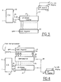
- a metering device including a combined sigma-delta multiplier 20, an up-down counter 21, a shift register 22, and an up counter 24.
- the value of the voltage V and current I to be metered are fed to the combined sigma-delta 20 which produces at line 25 a product signal representative of the energy V.I together with a clock signal on line 26, fed to the up-down counter 21.
- the product signal at line 25 comprises a stream of positive and negative pulses, each positive pulse incrementing the counter by one and each negative pulse decrementing the counter by one, but in which there are more positive pulses than negative i.e. such that N+ - N ⁇ will be a positive value.
- the sum stored in the up-down counter thus gradually accumulates until the maximum value storable in the up-down counter is reached, at which point a single positive pulse is output on line 27 to the up counter 24, and the converter is reset to zero.
- the up counter 24 in turn counts the number of times this occurs, representative of the difference N+ - N ⁇ , and outputs a signal to an LED display and associated circuitry.
- the circuit additionally comprises a shift register 22, for holding a numerical gain value set by a central microprocessor (not shown) delivered to the up-down counter 21.
- the numerical gain value held in the shift register is simply added to the total in the up-down counter, such that the upward count of the counter to its maximum value will start from a non-zero point.
- the numerical value held in the shift register 22 may be varied alter the gain of the device. As the magnitude of the product signal is represented by the difference between the counted number of positive and negative pulses, simple addition of a predetermined gain value to the sum stored in the counter 21 will have a linear effect on the gain of the converter over all magnitudes of input energy.
- FIG. 4 An alternative embodiment is shown in Fig. 4, in which the total in the up-down converter 21 is compared by a comparator 32 with a gain value stored in a shift register 33.
- the binary value of the sum in the up-down counter is output on a series of lines 34, each line carrying the value 0 or 1, each line representing a digit of the binary word from the least significant bit to the most significant bit.
- the gain value is similarly output on a series of lines 37, each line being connected to an input of an exclusive OR gate 36, the other input being fed by a polarity signal from a central microprocessor, the output line 35 of each gate being compared by the comparator 32 with the corresponding line 34 of the up-down counter.
- the exclusive OR gates 36 function to deliver the complement of the value of the corresponding line 37 when the polarity input is set high, i.e. such that an input 11001... becomes 00110...
- the value of the gain parameter stored in the shift register 33 is set by a central microprocessor (not shown). If the sigma-delta converter 20 is operating in a mainly positive mode, the polarity signal is set low and the counter counts up from zero. When the comparator identifies that the sum in the up-down counter 21 has reached the value stored in the shift register 33, a signal is output on line 38 which acts to reset the counter to zero to restart the count, the number of signals at line 38 being counted by an up counter 24 as before to give an indication of power consumed to an LED display or similar.
- the gain of the device may be adjusted by setting the level of the gain value in the shift register 33, such that the count will be completed at higher or lower levels.
- the polarity signal will be set high by the microprocessor.
- the overall polarity of the output pulses may be determined by the microprocessor from the output line 25 or from other parameters in the sigma-delta circuit, for example, the polarity of any modulation signal applied to the sigma-delta converter.
- a stream of negative pulses will cause the counter to switch from a starting value of 000... to 111..., i.e. the maximum value of the counter, each subsequent negative pulse decrementing this value.
- the polarity signal compensates for this change in operation by delivering the complement of the gain value for comparison by the comparator 32.
- a gain value set to 101 will be reached in 5 positive steps from 000 by the counter 21.
- the polarity signal will be high and the complement 010 of the gain value will be delivered to the comparator 32 such that the counter will reach this value in 5 negative steps down from the value 111.
Landscapes
- Engineering & Computer Science (AREA)
- Physics & Mathematics (AREA)
- Theoretical Computer Science (AREA)
- General Physics & Mathematics (AREA)
- Mathematical Physics (AREA)
- Computer Hardware Design (AREA)
- Software Systems (AREA)
- Power Engineering (AREA)
- Mathematical Analysis (AREA)
- General Engineering & Computer Science (AREA)
- Pure & Applied Mathematics (AREA)
- Mathematical Optimization (AREA)
- Computing Systems (AREA)
- Computational Mathematics (AREA)
- Automation & Control Theory (AREA)
- Evolutionary Computation (AREA)
- Fuzzy Systems (AREA)
- Compression, Expansion, Code Conversion, And Decoders (AREA)
- Measurement Of Radiation (AREA)
- Measuring Instrument Details And Bridges, And Automatic Balancing Devices (AREA)
Abstract
Description
- The present invention relates to an electricity metering device including at least one sigma-delta converter adapted to output a series of digital pulses, a digital counter means for summing the output of the sigma-delta converter and a signalling means to deliver an output signal when the sum reaches a predetermined value.
- Sigma-delta converters are well-known analogue to digital converters, in which an analogue input voltage is summed with a larger reference voltage, the sum being integrated and the running total of the integrator being fed to a clocked comparator which produces a positive or negative output depending on the results of the comparison. The positive or negative output of the comparator is fed back to control the polarity of the reference voltage, the polarity being controlled to tend to bring the charge in the integrator towards zero. The clocked output of the comparator over a period of time is thus a series of digital pulses of +1 or -1, in which the magnitude of the input voltage is represented by the difference between the number of positive comparator output pulses and the number of negative comparator output pulses, i.e. N⁺ - N⁻. The series of output of pulses of the sigma-delta may then be summed, by an integrator or by an up/down counter, in order to arrive at the digital value corresponding to the input voltage. Combined sigma-delta devices are also known (see
FR 2 570 854) in which a first signal is fed to a first sigma-delta converter and a second signal to a second sigma-delta converter, the polarity of the second input signal being controlled according to the pulsed output of the first sigma-delta converter. The output of the second sigma-delta converter then represents the product of the first and second signals. - Such sigma-delta circuits find a particular application in the field of the electricity metering, where the voltage of the power supply and/or the value of current taken, as represented by a voltage across a shunt for example, may be converted into digital signals. The combination sigma-delta converter discussed above is particularly useful in metering systems as voltage and current signals may be fed to the first and second converters respectively, the output of the second converter representing the product of the signals, i.e. the energy being taken.
- In the field of electricity metering problems arise particularly related to the accuracy of the components used to sample the voltage and current values. For example, where a simple shunt is used to provide a voltage signal representative of the current, errors may arise associated with the exact value of the resistance used in the shunt, the variation of this resistance with temperature etc. Similar errors can arise in the measurement of the supply voltage due to component inaccuracies in the voltage divider used to sample the voltage. These inaccuracies will be multiplied when the power or energy of the supply is measured and quite significant errors can result from this combination, together with any further deviations introduced by variations in the components used in the multiplier.
- In order to overcome such errors, previous methods of calibrating meters have concentrated on adjusting or trimming the components used, for example, by setting the value of a variable resistance shunt during a precalibration phase. Such precalibration tends to be time-consuming and expensive as each meter has to be tested and components manually re-adjusted or replaced.
- The present invention is characterized in that the metering device further comprises a means for digitally adjusting the gain of the sigma-delta converter comprising a programmable digital memory means adapted to store a parameter representing the gain of the metering device, the value of the parameter being externally programmable, and a digital logic means for logically combining the gain parameter with the digital sum stored in the counter means to determine the number of pulses required before the predetermined value is reached and an output pulse delivered.
- Thus, any variations in meter performance due to component inaccuracies can be quickly and easily compensated for during a calibration stage by merely reprogramming the gain parameter to an appropriate value which gives the desired readings. The programmable memory means may be a non-volatile memory and may comprise a simple shift register which stores a digital value representing the gain. Once set, the gain of the meter will be fixed unless reprogramming is required at any time during the life of the meter. The present invention also gives rise to the advantage that a basic meter design including fixed values of components may be used in a variety of applications to measure a wide range of current and voltage values through selection of the desired values of gain of the meter.
- In a metering device including a plurality of sigma-delta converters, the gain of each converter may be adjustable by means of an associated programmable memory means and logic means as described above. The invention further extends to a metering device comprising a combination of sigma-delta devices operating to give a value representative of the multiplication of the input signals and in which the gain of the final sigma-delta converter of the combination which produces an output representative of the energy or power of the metered supply is adjustable by means of an associated programmable digital memory means and logic means.
- The output signal from the signalling means may further be supplied to an additional counter means to control a meter output display.
- In one embodiment, the counter means and signalling means comprise a counter adapted to give an output signal when the counter reaches a fixed predetermined value (such as its maximum value) and in which the gain parameter is a numerical value added by the logic means to the counter in addition to the pulses from the sigma-delta converter.
- As discussed above, the value of an input signal to the sigma-delta converter is represented by the difference between the number of up and down pulses from the converter, i.e. N⁺ - N⁻. The counter counts the number of positive pulses (or negative) or the difference between the two, rather than the ratio between the two. Simple addition of a numerical value will thus have a linear effect on the gain of the converter for all magnitudes of input signals.
- Alternatively, the logic means and signalling means may comprise a comparator adapted to compare the value of the gain parameter with the value of the sum in the counter means and to deliver an output signal when the two values are equal. Again, the number of positive or negative pulses represents directly the magnitude of the input signal and changing the value of the gain parameter to change the count at which an output signal is delivered will give rise to a linear change in gain across all magnitudes of the input signal.
- The digital counter means for summing the sigma-delta pulses may comprise any suitable counter, such as a simple up counter, in which the sum in the counter represents the number of up pulses only, an up-down binary counter, a counter operating in a non-binary base etc.
- Depending on the details of the sigma-delta converter used, the overall polarity of pulses output from the sigma-delta converter may reflect the overall polarity of the input signal or signals (either directly or inversely) such that, in some instances, the majority of pulses supplied will be positive whilst, in other instances, the pulses supplied will be largely negative. The output of the sigma-delta will then switch from a majority of positive pulses to a majority of negative pulses, according to the mode of operation. This will affect the operation of the counter which, typically, comprises a simple up-down binary counter which can count up from a value 000...000 to 111...111 or down from a value 111...111 to 000...000 depending on the polarity of the pulses.
- The invention may then further comprise means for compensating for the polarity of pulses from the sigma-delta converter. For example, in the embodiment in which the numerical sum of the counter is compared directly with the gain parameter, the counter may comprise a binary up-down counter and the device may further comprise means for supplying the binary complement of the gain parameter to the comparator. For example, consider the case of a 3 bit binary counter capable of counting up from 000 to 111 or down from 111 to 000. If the gain parameter is set to 101 for a positive count, it will take 5 positive pulses for the counter to reach 101 from 000 and for the comparator to output a signal. In the alternative direction of the count, where mainly negative pulses are output, the complement of 101 is supplied, that is 010. In such operation, the counter will start from 111 and, again, it will take 5 negative pulses to reach 010 from 111.
- There will now be described, by way of example only, preferred embodiments of the present invention, with reference to the accompanying drawings, in which :
- Fig. 1 shows a conventional sigma-delta device for converting an analogue signal into a digital form;
- Fig. 2 shows a combined sigma-delta device for turning the analogue signals in a digital value representative of the product of those signals;
- Fig. 3 shows a metering device including a combined sigma-delta circuit and a variable digital gain according to one embodiment of the invention;
- Fig. 4 shows a metering device including a combined sigma-delta circuit and variable digital gain according to a second embodiment of the invention.
- Referring to Fig. 1, a sigma-
delta converter 1 is shown, comprising anintegrator 2, a comparator 3, a bistable 4 and aswitch 5 and inverter 6. An input signal E1 is fed to theintegrator 2, summed with a reference signal R1, the polarity of the reference R1 being determined by theswitch 5 and inverter 6, as controlled by the output Q from the bistable 4. The reference signal R1 is chosen to have a magnitude greater than the maximum value of E1. The output Q, and the polarity of the reference signal R1 is determined by the comparator 3. The comparator and inverter act to minimise the change in the integrator, that is, to tend to bring the charge in the integrator towards zero. The bistable 4 acts to change the polarity of R1 with each interval of a CLOCK signal. After N clock signals, the reference voltage will have been applied N⁺ times with a positive polarity and N⁻ times with a negative polarity. If N is large enough the change stored in the integrator will tend to zero, such that :

where t is the duration of each clock time interval and the integrated values of E1 and R1 represent the corresponding charge stored at each clock interval. - Thus: :
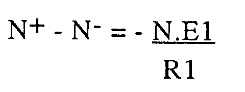
such that the difference between the number of positive pulses applied and the number of negative pulses is proportional to the magnitude of the input signal. This information is available in the output Q1 from the sigma-delta converter. - Referring to Fig. 2, a combined sigma-delta converter circuit is shown comprising a first sigma-
delta converter 10 fed with a first input signal E1 and reference signal R1 and a second sigma-delta converter 11 fed with a second input signal E2 and reference R2. The structure of each converter is the same as that shown in Fig. 1. The output Q1 additionally controls the polarity of the input signal E2 via aswitch 12 and inverter 13, according to whether a positive or negative pulse is output on the line Q1. At the end of a time interval N, the sigma-delta 10 will have output N1⁺ positive signals and N1⁻ negative signals, such that a signal E2 will have been applied N2+ times and a signal -E2 will have been applied N1⁻ times to theconverter 11. Accordingly, in the same manner as for a single converter, for the converter 11 :

where N2⁺ and N2⁻ are the number of times the reference R2 has been applied, as controlled by the output Q2 ofconverter 11. - However, for the first converter 10 :

such that :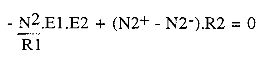
and :

where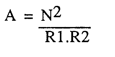
Accordingly, the difference N2⁺ - N2⁻ as represented by the output Q2 will be proportional to the product of the input signals. This circuit is particularly useful in the field of electricity metering where the inputs E1 and E2 are the voltage and current, the circuit giving a value representative of the energy of the metered supply. Conventionally, the output from the combined sigma-delta arrangement is fed to an integrator or up-down counter 14 the running total of which is increased by each positive pulse or decremented by each negative pulse to give a running total corresponding to the energy consumed. - As discussed in the introduction to the present application, the conventional utilisation of sigma-delta circuits in electricity metering applications gives rise to a number of problems of accurate calibration of the meter associated with variations in component values etc. Previous attempts to improve the calibration of such meters have focussed on improving the component tolerances.
- Referring to Fig. 3, a metering device according to one embodiment of the invention is shown including a combined sigma-
delta multiplier 20, an up-down counter 21, ashift register 22, and an upcounter 24. The value of the voltage V and current I to be metered are fed to the combined sigma-delta 20 which produces at line 25 a product signal representative of the energy V.I together with a clock signal online 26, fed to the up-down counter 21. In the simplest embodiment shown here, the product signal atline 25 comprises a stream of positive and negative pulses, each positive pulse incrementing the counter by one and each negative pulse decrementing the counter by one, but in which there are more positive pulses than negative i.e. such that N⁺ - N⁻ will be a positive value. The sum stored in the up-down counter thus gradually accumulates until the maximum value storable in the up-down counter is reached, at which point a single positive pulse is output online 27 to the up counter 24, and the converter is reset to zero. The up counter 24 in turn counts the number of times this occurs, representative of the difference N⁺ - N⁻, and outputs a signal to an LED display and associated circuitry. - The circuit additionally comprises a
shift register 22, for holding a numerical gain value set by a central microprocessor (not shown) delivered to the up-down counter 21. In this embodiment, the numerical gain value held in the shift register is simply added to the total in the up-down counter, such that the upward count of the counter to its maximum value will start from a non-zero point. The numerical value held in theshift register 22 may be varied alter the gain of the device. As the magnitude of the product signal is represented by the difference between the counted number of positive and negative pulses, simple addition of a predetermined gain value to the sum stored in thecounter 21 will have a linear effect on the gain of the converter over all magnitudes of input energy. - An alternative embodiment is shown in Fig. 4, in which the total in the up-
down converter 21 is compared by acomparator 32 with a gain value stored in ashift register 33. The binary value of the sum in the up-down counter is output on a series oflines 34, each line carrying thevalue 0 or 1, each line representing a digit of the binary word from the least significant bit to the most significant bit. The gain value is similarly output on a series oflines 37, each line being connected to an input of an exclusive ORgate 36, the other input being fed by a polarity signal from a central microprocessor, theoutput line 35 of each gate being compared by thecomparator 32 with thecorresponding line 34 of the up-down counter. The exclusive ORgates 36 function to deliver the complement of the value of thecorresponding line 37 when the polarity input is set high, i.e. such that an input 11001... becomes 00110... - In operation, the value of the gain parameter stored in the
shift register 33 is set by a central microprocessor (not shown). If the sigma-delta converter 20 is operating in a mainly positive mode, the polarity signal is set low and the counter counts up from zero. When the comparator identifies that the sum in the up-down counter 21 has reached the value stored in theshift register 33, a signal is output online 38 which acts to reset the counter to zero to restart the count, the number of signals atline 38 being counted by an up counter 24 as before to give an indication of power consumed to an LED display or similar. The gain of the device may be adjusted by setting the level of the gain value in theshift register 33, such that the count will be completed at higher or lower levels. - In the event that the sigma-delta converter outputs mainly negative signals the polarity signal will be set high by the microprocessor. The overall polarity of the output pulses may be determined by the microprocessor from the
output line 25 or from other parameters in the sigma-delta circuit, for example, the polarity of any modulation signal applied to the sigma-delta converter. For a simple up-down counter not having a polarity bit indicative of the polarity in the counter, a stream of negative pulses will cause the counter to switch from a starting value of 000... to 111..., i.e. the maximum value of the counter, each subsequent negative pulse decrementing this value. The polarity signal compensates for this change in operation by delivering the complement of the gain value for comparison by thecomparator 32. For example, for a simple 3 bit counter/comparator/register arrangement, a gain value set to 101 will be reached in 5 positive steps from 000 by thecounter 21. For a negative count, the polarity signal will be high and the complement 010 of the gain value will be delivered to thecomparator 32 such that the counter will reach this value in 5 negative steps down from the value 111.
Claims (8)
- An electricity metering device including at least one sigma-delta converter adapted to output a series of digital pulses, a digital counter means for summing the output of the sigma-delta converter and a signalling means to deliver an output signal when the sum reaches a predetermined value, characterised in that the metering device further comprises a means for digitally adjusting the gain of the sigma-delta converter comprising a programmable digital memory means adapted to store a parameter representing the gain of the metering device, the value of the parameter being externally programmable, and a digital logic means for logically combining the gain parameter with the digital sum stored in the counter means to determine the number of pulses required before the predetermined value is reached and an output pulse delivered.
- An electricity metering device as claimed in claim 1 in which the counter means and signalling means comprise a counter adapted to give an output signal when the counter reaches a fixed predetermined value and in which the gain parameter is a numerical value added by the logic means to the counter in addition to the pulses from the sigma-delta converter.
- An electricity metering device as claimed in claim 2 in which the output signal from the counter is fed to an additional counter means to control a meter output display dependent on the number of output signals counted.
- An electricity metering device as claimed in claim 1 in which the logic means and signalling means comprise a comparator adapted to compare the value of the gain parameter with the value of the sum in the counter means and to deliver an output signal when the two values are equal.
- An electricity metering device as claimed in claim 4, in which the counter means is a binary up-down counter and further comprising means connected between the comparator and the memory means for supplying the binary complement of the gain parameter to the comparator for compensating for the polarity of the pulses output from the sigma-delta converter .
- An electricity metering device as claimed in claim 4 or 5 in which the output signal from the comparator is fed to an additional counter means to control a meter output display dependent on the number of output signals counted.
- An electricity metering device as claimed in any preceding claim comprising a plurality of sigma-delta converters, the gain of each converter being adjustable by means of an associated programmable memory means and logic means.
- An electricity metering device as claimed in any preceding claim comprising a combination of sigma-delta devices operating to give a value representative of the multiplication of input signals representing the current and voltage of a metered supply, the gain of the final sigma-delta of the combination which produces an output representative of the energy or power of the metered supply being adjustable by means of an associated programmable memory means and logic means.
Priority Applications (8)
| Application Number | Priority Date | Filing Date | Title |
|---|---|---|---|
| AT93400129T ATE178412T1 (en) | 1993-01-20 | 1993-01-20 | ELECTRICITY METER WITH VARIABLE GAIN AND WITH SIGMA-DELTA CONVERTER |
| DK93400129T DK0607711T3 (en) | 1993-01-20 | 1993-01-20 | Variable gain electricity meter with sigma-delta converter |
| ES93400129T ES2131561T3 (en) | 1993-01-20 | 1993-01-20 | ELECTRICAL METER WITH VARIABLE GAIN AND WITH SIGMA-DELTA CONVERTER. |
| DE69324229T DE69324229T2 (en) | 1993-01-20 | 1993-01-20 | Electricity meter with variable gain and with sigma-delta converter |
| EP93400129A EP0607711B1 (en) | 1993-01-20 | 1993-01-20 | Electricity meter with variable gain and with sigma-delta converter |
| RU94001563/09A RU2117303C1 (en) | 1993-01-20 | 1994-01-19 | Device which measures electric power consumption and contains alternating-gain sigma-delta transducer |
| US08/446,965 US5493212A (en) | 1993-01-20 | 1995-05-22 | Electricity meter with variable gain sigma-delta converter |
| GR990401315T GR3030228T3 (en) | 1993-01-20 | 1999-05-14 | Electricity meter with variable gain sigma-delta converter. |
Applications Claiming Priority (1)
| Application Number | Priority Date | Filing Date | Title |
|---|---|---|---|
| EP93400129A EP0607711B1 (en) | 1993-01-20 | 1993-01-20 | Electricity meter with variable gain and with sigma-delta converter |
Publications (2)
| Publication Number | Publication Date |
|---|---|
| EP0607711A1 true EP0607711A1 (en) | 1994-07-27 |
| EP0607711B1 EP0607711B1 (en) | 1999-03-31 |
Family
ID=8214665
Family Applications (1)
| Application Number | Title | Priority Date | Filing Date |
|---|---|---|---|
| EP93400129A Expired - Lifetime EP0607711B1 (en) | 1993-01-20 | 1993-01-20 | Electricity meter with variable gain and with sigma-delta converter |
Country Status (8)
| Country | Link |
|---|---|
| US (1) | US5493212A (en) |
| EP (1) | EP0607711B1 (en) |
| AT (1) | ATE178412T1 (en) |
| DE (1) | DE69324229T2 (en) |
| DK (1) | DK0607711T3 (en) |
| ES (1) | ES2131561T3 (en) |
| GR (1) | GR3030228T3 (en) |
| RU (1) | RU2117303C1 (en) |
Cited By (5)
| Publication number | Priority date | Publication date | Assignee | Title |
|---|---|---|---|---|
| EP0699914A1 (en) * | 1994-09-05 | 1996-03-06 | Landis & Gyr Technology Innovation AG | Electricity meter |
| DE19630605A1 (en) * | 1996-07-29 | 1998-02-05 | Tech Gmbh Antriebstechnik Und | Multiplication circuit for power measuring device |
| EP1077530A1 (en) * | 1999-08-16 | 2001-02-21 | STMicroelectronics SA | Method and arrangement for the conversion of an analogue signal into a digital signal with automatic gain control |
| US6496783B1 (en) | 1999-03-05 | 2002-12-17 | Kabushiki Kaisha Toshiba | Electric power calculation system |
| US11557430B2 (en) | 2020-02-19 | 2023-01-17 | Eaton Intelligent Power Limited | Current transformer powered controller |
Families Citing this family (3)
| Publication number | Priority date | Publication date | Assignee | Title |
|---|---|---|---|---|
| JP2003016767A (en) * | 2001-06-27 | 2003-01-17 | Sony Corp | Signal level detecting device and method, and signal level display device |
| DE10311777B4 (en) * | 2003-03-18 | 2005-10-20 | Thomas Schoch | Method, measuring system and device for electrical power measurement |
| EP2927805A1 (en) * | 2014-03-31 | 2015-10-07 | Nxp B.V. | Control system |
Citations (5)
| Publication number | Priority date | Publication date | Assignee | Title |
|---|---|---|---|---|
| US4409660A (en) * | 1981-03-03 | 1983-10-11 | Fischer & Porter Company | Electronic totalizer |
| GB2118726A (en) * | 1982-04-13 | 1983-11-02 | Plessey Co Plc | Mains power measurement |
| US4692933A (en) * | 1986-03-24 | 1987-09-08 | The Babcock & Wilcox Company | Electro-mechanical integrator |
| US4722094A (en) * | 1985-12-16 | 1988-01-26 | Allied Corporation | Digital rate detection circuit |
| US4761606A (en) * | 1986-12-22 | 1988-08-02 | General Electric Company | Auto-ranging in electric watthour meter |
Family Cites Families (3)
| Publication number | Priority date | Publication date | Assignee | Title |
|---|---|---|---|---|
| US4081800A (en) * | 1974-10-24 | 1978-03-28 | Tokyo Shibaura Electric Co., Ltd. | Analog-to-digital converter |
| FR2570854B1 (en) * | 1984-09-25 | 1991-01-04 | Enertec | SIGNAL PROCESSING METHOD AND DEVICE |
| US5245343A (en) * | 1990-08-03 | 1993-09-14 | Honeywell Inc. | Enhanced accuracy delta-sigma A/D converter |
-
1993
- 1993-01-20 AT AT93400129T patent/ATE178412T1/en not_active IP Right Cessation
- 1993-01-20 ES ES93400129T patent/ES2131561T3/en not_active Expired - Lifetime
- 1993-01-20 EP EP93400129A patent/EP0607711B1/en not_active Expired - Lifetime
- 1993-01-20 DE DE69324229T patent/DE69324229T2/en not_active Expired - Fee Related
- 1993-01-20 DK DK93400129T patent/DK0607711T3/en active
-
1994
- 1994-01-19 RU RU94001563/09A patent/RU2117303C1/en not_active IP Right Cessation
-
1995
- 1995-05-22 US US08/446,965 patent/US5493212A/en not_active Expired - Lifetime
-
1999
- 1999-05-14 GR GR990401315T patent/GR3030228T3/en unknown
Patent Citations (5)
| Publication number | Priority date | Publication date | Assignee | Title |
|---|---|---|---|---|
| US4409660A (en) * | 1981-03-03 | 1983-10-11 | Fischer & Porter Company | Electronic totalizer |
| GB2118726A (en) * | 1982-04-13 | 1983-11-02 | Plessey Co Plc | Mains power measurement |
| US4722094A (en) * | 1985-12-16 | 1988-01-26 | Allied Corporation | Digital rate detection circuit |
| US4692933A (en) * | 1986-03-24 | 1987-09-08 | The Babcock & Wilcox Company | Electro-mechanical integrator |
| US4761606A (en) * | 1986-12-22 | 1988-08-02 | General Electric Company | Auto-ranging in electric watthour meter |
Non-Patent Citations (1)
| Title |
|---|
| ELECTRONIC ENGINEERING vol. 46, no. 558, August 1974, pages 38 - 40 'versatile integrator-multiplier' * |
Cited By (10)
| Publication number | Priority date | Publication date | Assignee | Title |
|---|---|---|---|---|
| EP0699914A1 (en) * | 1994-09-05 | 1996-03-06 | Landis & Gyr Technology Innovation AG | Electricity meter |
| US5736848A (en) * | 1994-09-05 | 1998-04-07 | Landis & Gyr Technology Innovation Ag | Analog-to-digital measurement and calibration system for electrical energy |
| DE19630605A1 (en) * | 1996-07-29 | 1998-02-05 | Tech Gmbh Antriebstechnik Und | Multiplication circuit for power measuring device |
| WO1998004926A1 (en) * | 1996-07-29 | 1998-02-05 | D-Tech Gmbh Antriebstechnik Und Mikroelektronik | Sigma-delta multiplier circuit for power measurement equipment |
| US6496783B1 (en) | 1999-03-05 | 2002-12-17 | Kabushiki Kaisha Toshiba | Electric power calculation system |
| DE10010545B4 (en) * | 1999-03-05 | 2004-03-25 | Kabushiki Kaisha Toshiba, Kawasaki | Electrical power calculation system |
| EP1077530A1 (en) * | 1999-08-16 | 2001-02-21 | STMicroelectronics SA | Method and arrangement for the conversion of an analogue signal into a digital signal with automatic gain control |
| FR2797725A1 (en) * | 1999-08-16 | 2001-02-23 | St Microelectronics Sa | METHOD AND DEVICE FOR CONVERTING AN ANALOG SIGNAL INTO A DIGITAL SIGNAL WITH AUTOMATIC GAIN CONTROL |
| US6680680B1 (en) | 1999-08-16 | 2004-01-20 | Stmicroelectronics S.A. | Process and device for converting an analog signal into a digital signal with automatic gain control |
| US11557430B2 (en) | 2020-02-19 | 2023-01-17 | Eaton Intelligent Power Limited | Current transformer powered controller |
Also Published As
| Publication number | Publication date |
|---|---|
| ES2131561T3 (en) | 1999-08-01 |
| GR3030228T3 (en) | 1999-08-31 |
| EP0607711B1 (en) | 1999-03-31 |
| DE69324229T2 (en) | 1999-09-30 |
| RU2117303C1 (en) | 1998-08-10 |
| DK0607711T3 (en) | 1999-10-18 |
| ATE178412T1 (en) | 1999-04-15 |
| US5493212A (en) | 1996-02-20 |
| DE69324229D1 (en) | 1999-05-06 |
| RU94001563A (en) | 1996-04-27 |
Similar Documents
| Publication | Publication Date | Title |
|---|---|---|
| US7078961B2 (en) | Device and method for calibrating R/C filter circuits | |
| US4250449A (en) | Digital electric energy measuring circuit | |
| US4943955A (en) | Atomic clock | |
| US5099209A (en) | Battery voltage detecting device | |
| EP0607711B1 (en) | Electricity meter with variable gain and with sigma-delta converter | |
| US4118698A (en) | Analog-to-digital converter recalibration method and apparatus | |
| US4238784A (en) | Electronic measuring system with pulsed power supply and stability sensing | |
| US4568913A (en) | High speed integrating analog-to-digital converter | |
| US4164733A (en) | Quantized feedback analog to digital converter with offset voltage compensation | |
| US4761606A (en) | Auto-ranging in electric watthour meter | |
| US6680615B2 (en) | Method and device for checking the charge state of a battery, in particular a rechargeable battery for a cellular mobile telephone | |
| US4143318A (en) | Wide range digital meter | |
| US5146157A (en) | Calculation apparatus for an electronic meter | |
| US4270119A (en) | Dual slope system A-D converter | |
| US4081800A (en) | Analog-to-digital converter | |
| CA1241061A (en) | Solid state electronic pulse scaler using ratio of two integers | |
| EP0871040A2 (en) | Calibration method for an electronic electricity meter | |
| US4847620A (en) | Clock-controlled voltage-to-frequency converter | |
| KR950000418B1 (en) | Pulse width measurement with quantisation error compensation | |
| US6369634B1 (en) | Delay systems and methods using a variable delay sinc filter | |
| EP0772052A1 (en) | Improvements in or relating to electricity meters | |
| SU1256202A2 (en) | Device for measuring distribution function of random error of analog-to-digital converter | |
| US4277747A (en) | Wide range digital meter | |
| JP2548418B2 (en) | Delay device | |
| RU2210783C2 (en) | Converter of time scale |
Legal Events
| Date | Code | Title | Description |
|---|---|---|---|
| PUAI | Public reference made under article 153(3) epc to a published international application that has entered the european phase |
Free format text: ORIGINAL CODE: 0009012 |
|
| AK | Designated contracting states |
Kind code of ref document: A1 Designated state(s): AT BE CH DE DK ES FR GB GR IT LI NL SE |
|
| 17P | Request for examination filed |
Effective date: 19941230 |
|
| 17Q | First examination report despatched |
Effective date: 19970725 |
|
| GRAG | Despatch of communication of intention to grant |
Free format text: ORIGINAL CODE: EPIDOS AGRA |
|
| GRAG | Despatch of communication of intention to grant |
Free format text: ORIGINAL CODE: EPIDOS AGRA |
|
| GRAH | Despatch of communication of intention to grant a patent |
Free format text: ORIGINAL CODE: EPIDOS IGRA |
|
| GRAH | Despatch of communication of intention to grant a patent |
Free format text: ORIGINAL CODE: EPIDOS IGRA |
|
| GRAA | (expected) grant |
Free format text: ORIGINAL CODE: 0009210 |
|
| AK | Designated contracting states |
Kind code of ref document: B1 Designated state(s): AT BE CH DE DK ES FR GB GR IT LI NL SE |
|
| REF | Corresponds to: |
Ref document number: 178412 Country of ref document: AT Date of ref document: 19990415 Kind code of ref document: T |
|
| REG | Reference to a national code |
Ref country code: CH Ref legal event code: EP |
|
| REF | Corresponds to: |
Ref document number: 69324229 Country of ref document: DE Date of ref document: 19990506 |
|
| ITF | It: translation for a ep patent filed | ||
| REG | Reference to a national code |
Ref country code: CH Ref legal event code: NV Representative=s name: A. BRAUN, BRAUN, HERITIER, ESCHMANN AG PATENTANWAE |
|
| ET | Fr: translation filed | ||
| REG | Reference to a national code |
Ref country code: ES Ref legal event code: FG2A Ref document number: 2131561 Country of ref document: ES Kind code of ref document: T3 |
|
| REG | Reference to a national code |
Ref country code: DK Ref legal event code: T3 |
|
| PGFP | Annual fee paid to national office [announced via postgrant information from national office to epo] |
Ref country code: GR Payment date: 19991230 Year of fee payment: 8 |
|
| PLBE | No opposition filed within time limit |
Free format text: ORIGINAL CODE: 0009261 |
|
| STAA | Information on the status of an ep patent application or granted ep patent |
Free format text: STATUS: NO OPPOSITION FILED WITHIN TIME LIMIT |
|
| 26N | No opposition filed | ||
| PG25 | Lapsed in a contracting state [announced via postgrant information from national office to epo] |
Ref country code: GR Free format text: LAPSE BECAUSE OF NON-PAYMENT OF DUE FEES Effective date: 20010131 |
|
| REG | Reference to a national code |
Ref country code: GB Ref legal event code: IF02 |
|
| REG | Reference to a national code |
Ref country code: FR Ref legal event code: GC |
|
| BECH | Be: change of holder |
Owner name: *SCHLUMBERGER ELECTRICITY INC. Effective date: 20040202 |
|
| REG | Reference to a national code |
Ref country code: CH Ref legal event code: PUE Owner name: SCHLUMBERGER INDUSTRIES S.A. Free format text: SCHLUMBERGER INDUSTRIES S.A.#50, AVENUE JEAN-JAURES#92120 MONTROUGE (FR) -TRANSFER TO- SCHLUMBERGER INDUSTRIES S.A.#313-B NORTH HIGHWAY 11#WEST UNION, SC 29696 (US) Ref country code: CH Ref legal event code: NV Representative=s name: DR. LUSUARDI AG |
|
| REG | Reference to a national code |
Ref country code: CH Ref legal event code: PUE Owner name: SCHLUMBERGER INDUSTRIES S.A. Free format text: SCHLUMBERGER INDUSTRIES S.A.#50, AVENUE JEAN-JAURES#92120 MONTROUGE (FR) -TRANSFER TO- SCHLUMBERGER INDUSTRIES S.A.#313-B NORTH HIGHWAY 11#WEST UNION, SC 29696 (US) Ref country code: CH Ref legal event code: PK Free format text: RECTIFICATION. Ref country code: CH Ref legal event code: NV Representative=s name: DR. LUSUARDI AG |
|
| NLS | Nl: assignments of ep-patents |
Owner name: SCHLUMBERGER ELECTRICITY, INC. |
|
| NLT1 | Nl: modifications of names registered in virtue of documents presented to the patent office pursuant to art. 16 a, paragraph 1 |
Owner name: SCHLUMBERGER S.A. |
|
| REG | Reference to a national code |
Ref country code: FR Ref legal event code: DG |
|
| REG | Reference to a national code |
Ref country code: FR Ref legal event code: TP |
|
| REG | Reference to a national code |
Ref country code: GB Ref legal event code: 732E |
|
| PGFP | Annual fee paid to national office [announced via postgrant information from national office to epo] |
Ref country code: ES Payment date: 20090126 Year of fee payment: 17 Ref country code: DK Payment date: 20090130 Year of fee payment: 17 Ref country code: AT Payment date: 20090102 Year of fee payment: 17 |
|
| PGFP | Annual fee paid to national office [announced via postgrant information from national office to epo] |
Ref country code: NL Payment date: 20090124 Year of fee payment: 17 Ref country code: DE Payment date: 20090302 Year of fee payment: 17 |
|
| PGFP | Annual fee paid to national office [announced via postgrant information from national office to epo] |
Ref country code: GB Payment date: 20090129 Year of fee payment: 17 Ref country code: CH Payment date: 20090126 Year of fee payment: 17 |
|
| PGFP | Annual fee paid to national office [announced via postgrant information from national office to epo] |
Ref country code: BE Payment date: 20090219 Year of fee payment: 17 |
|
| PGFP | Annual fee paid to national office [announced via postgrant information from national office to epo] |
Ref country code: SE Payment date: 20090128 Year of fee payment: 17 Ref country code: IT Payment date: 20090129 Year of fee payment: 17 |
|
| PGFP | Annual fee paid to national office [announced via postgrant information from national office to epo] |
Ref country code: FR Payment date: 20090119 Year of fee payment: 17 |
|
| BERE | Be: lapsed |
Owner name: *SCHLUMBERGER ELECTRICITY INC. Effective date: 20100131 |
|
| REG | Reference to a national code |
Ref country code: NL Ref legal event code: V1 Effective date: 20100801 |
|
| REG | Reference to a national code |
Ref country code: CH Ref legal event code: PL |
|
| REG | Reference to a national code |
Ref country code: DK Ref legal event code: EBP |
|
| GBPC | Gb: european patent ceased through non-payment of renewal fee |
Effective date: 20100120 |
|
| EUG | Se: european patent has lapsed | ||
| REG | Reference to a national code |
Ref country code: FR Ref legal event code: ST Effective date: 20100930 |
|
| PG25 | Lapsed in a contracting state [announced via postgrant information from national office to epo] |
Ref country code: NL Free format text: LAPSE BECAUSE OF NON-PAYMENT OF DUE FEES Effective date: 20100801 Ref country code: LI Free format text: LAPSE BECAUSE OF NON-PAYMENT OF DUE FEES Effective date: 20100131 Ref country code: FR Free format text: LAPSE BECAUSE OF NON-PAYMENT OF DUE FEES Effective date: 20100201 Ref country code: CH Free format text: LAPSE BECAUSE OF NON-PAYMENT OF DUE FEES Effective date: 20100131 |
|
| PG25 | Lapsed in a contracting state [announced via postgrant information from national office to epo] |
Ref country code: DE Free format text: LAPSE BECAUSE OF NON-PAYMENT OF DUE FEES Effective date: 20100803 Ref country code: AT Free format text: LAPSE BECAUSE OF NON-PAYMENT OF DUE FEES Effective date: 20100120 |
|
| PG25 | Lapsed in a contracting state [announced via postgrant information from national office to epo] |
Ref country code: GB Free format text: LAPSE BECAUSE OF NON-PAYMENT OF DUE FEES Effective date: 20100120 |
|
| PG25 | Lapsed in a contracting state [announced via postgrant information from national office to epo] |
Ref country code: DK Free format text: LAPSE BECAUSE OF NON-PAYMENT OF DUE FEES Effective date: 20100131 |
|
| PG25 | Lapsed in a contracting state [announced via postgrant information from national office to epo] |
Ref country code: BE Free format text: LAPSE BECAUSE OF NON-PAYMENT OF DUE FEES Effective date: 20100131 |
|
| PG25 | Lapsed in a contracting state [announced via postgrant information from national office to epo] |
Ref country code: IT Free format text: LAPSE BECAUSE OF NON-PAYMENT OF DUE FEES Effective date: 20100120 |
|
| REG | Reference to a national code |
Ref country code: ES Ref legal event code: FD2A Effective date: 20111118 |
|
| PG25 | Lapsed in a contracting state [announced via postgrant information from national office to epo] |
Ref country code: ES Free format text: LAPSE BECAUSE OF NON-PAYMENT OF DUE FEES Effective date: 20100121 |
|
| PG25 | Lapsed in a contracting state [announced via postgrant information from national office to epo] |
Ref country code: SE Free format text: LAPSE BECAUSE OF NON-PAYMENT OF DUE FEES Effective date: 20100121 |