EP0607726A1 - Fermoir dépliant pour bracelet à brin réglable - Google Patents
Fermoir dépliant pour bracelet à brin réglable Download PDFInfo
- Publication number
- EP0607726A1 EP0607726A1 EP93420502A EP93420502A EP0607726A1 EP 0607726 A1 EP0607726 A1 EP 0607726A1 EP 93420502 A EP93420502 A EP 93420502A EP 93420502 A EP93420502 A EP 93420502A EP 0607726 A1 EP0607726 A1 EP 0607726A1
- Authority
- EP
- European Patent Office
- Prior art keywords
- cover
- base plate
- leaflet
- lateral
- clasp according
- Prior art date
- Legal status (The legal status is an assumption and is not a legal conclusion. Google has not performed a legal analysis and makes no representation as to the accuracy of the status listed.)
- Granted
Links
Images
Classifications
-
- A—HUMAN NECESSITIES
- A44—HABERDASHERY; JEWELLERY
- A44C—PERSONAL ADORNMENTS, e.g. JEWELLERY; COINS
- A44C5/00—Bracelets; Wrist-watch straps; Fastenings for bracelets or wrist-watch straps
- A44C5/18—Fasteners for straps, chains or the like
- A44C5/22—Fasteners for straps, chains or the like for closed straps
- A44C5/24—Fasteners for straps, chains or the like for closed straps with folding devices
Definitions
- the present invention relates to a folding clasp for an adjustable strand bracelet, in particular leather bracelets.
- the adjustable strand is connected to a first leaflet by a mechanism using one of the adjustment orifices, the other fixed strand being connected by a fastener to the end of the clasp spar either directly or through a second leaflet.
- the mechanism is formed of a loop comprising a base carrying a stud located slightly behind the loop and intended to engage in one adjustable strand openings.
- the bracelet is locked by folding down a cover installed in front of the loop which closes over the strand.
- the mechanism comprises a U-shaped cover with a cross member, two lateral branches and an axis connecting the lateral branches to one another.
- the adjustable strand of the leather strap is inserted between the crosspiece and the axis; and it is held in place by a barb pivoting freely around the axis and passing entirely through one of the adjustment holes of the strand before being inserted into a housing of the crosspiece.
- the object of the present invention is therefore a folding clasp for an adjustable strand bracelet which cannot be opened inadvertently, in particular at the level of the mechanism for holding this adjustable strand, while being of an easier adjustment for the user due to its simplified structure.
- a folding clasp for bracelet the adjustable strand of which is connected by a mechanism to a first leaflet and the fixed strand of which is connected by a fastener to the end of the side member of the clasp directly or through a second leaflet
- the mechanism comprises a base plate hingedly mounted at the end of its leaflet, as well as an inverted U-shaped cover extending beyond the base plate and the two free edges of which are respectively extended by the same side by a lateral arm, the end of which is mounted in rotation, close to the leaflet, to the corresponding lateral face of the base plate; the free edges of the cover being able to be locked by lateral means which can be detached from the lateral faces of the base plate; the adjustable strand passing between the base plate and the cover, and being held by a stud protruding from the internal face of this base or of the cover.
- the arms can be substantially as long as the U-shaped portion of the cover.
- the cover being, according to the invention, held by two arms, it therefore provides better clearance when it is opened, which provides better visibility of the stud when it is inserted into one of the openings of the adjustable strand.
- This movement of the hood being large, it is therefore possible to insert the strand without having to twist it, then lock the hood over the base with a reasonable effort.
- the arms of the cover are held on the same transverse axis connecting the base plate to the end of its leaflet, which greatly simplifies the structure of the mechanism.
- the length of the hood arms can be less than a fifth of the length of the U-shaped part of the hood, or even zero, to allow the length of the U-shaped part to be increased, which offers a larger area available for decorations. .
- the lateral locking means comprise a lug formed on each internal face of the free ends of the U-shaped part of the cover which engages in grooves formed in correspondence in the lateral faces of the base plate, or vice versa , grooves being formed in the ends of the cover.
- the lateral locking means comprise a rod with a rounded end or a ball emerging from each lateral face under the action of an internal spring housed in the thickness of the base plate, each internal face of the free ends of the U-shaped portion of the cover having a corresponding recess.
- the base plate has a concave or convex tab along the edge opposite the edge connected to the leaflet.
- the upper face of the U-shaped part of the cover has engraved decorative patterns and / or added relief decorations, possibly acting as a tab. These lower and upper tabs greatly facilitate the opening of the cover, when desired.
- the folding clasp comprises two parallel beams 10 connected at their ends to a straight leaflet 12 and to a thimble folding left 12 '.
- the free ends of these leaflets carry a hook 13 which comes to lock against transverse pins 11 installed transversely between the two longitudinal members 10.
- a fixed strand 6 is fixed to the left leaflet 12 'by means of a fastener 20.
- the base plate is substantially flattened parallelepiped and carries on the upper surface, as illustrated, a stud 36 located between two-thirds and three-quarters of the center line.
- the edge opposite the rotation edge (in the figure: the straight edge) is completed with a tab 32 in this case protruding, but can also be produced in the form of a concave groove.
- Two grooves 34 are cut in the lateral sides close to the edge carrying the tab.
- the cover 40 has a first inverted U-shaped part with an internal width slightly greater than the width of the base 30. This U-shaped part is held on either side by arms 43 extending the free edges on the same side. The ends of these arms 43 are pivotally mounted about the axis 31. The height of the free arms of the U-shaped part of the cover is equal to or slightly greater than the sum of the thickness of the base plate 30 and the 'thickness of the adjustable strand 2. As illustrated, the arms 43 are substantially as long as the U-shaped portion of the cover 40. Furthermore, two pins 42 are formed in the internal face of the free arms of the U-shaped portion of the cover 40.
- the stud 36 can also be fixed on the internal face of the upper part of the cover 40.
- the stud 42 can belong to the base 30, two grooves 34 then being formed under the cover 40.
- one can provide, in the thickness of the base 30, two balls or rods with rounded ends emerging from the lateral faces under the action of an internal spring.
- the arms 43 of the cover 40 are directly connected to the axis 31 of the leaflet 12, it is possible to substantially reduce, or even cancel, the length of these arms 43 to further increase that of the U-shaped portion of the cover 40.
- the height of the free arms of the U-shaped part of the cover always makes it possible to easily insert the free strand 2 between the cover and the rear edge, then rounded, of the base plate.
- This adjustable fixing mechanism can be adapted without difficulty to a folding clasp comprising only a single leaflet 12, the fixed strand being directly attached to the end of the side members 10, the leaflet then being substantially as long as the side members.
- this adjustable fixing mechanism can also be mounted on a folding clasp comprising only a single central spar 10, the leaflets then being produced by two parallel bars.
Landscapes
- Adornments (AREA)
- Buckles (AREA)
- Orthopedics, Nursing, And Contraception (AREA)
- Aerials With Secondary Devices (AREA)
Abstract
Description
- La présente invention est relative à un fermoir dépliant pour bracelet à brin réglable, notamment des bracelets en cuir. Dans de tels fermoirs, le brin réglable est relié a un premier dépliant par un mécanisme utilisant l'un des orifices de réglage, l'autre brin fixe étant relié par une attache à l'extrémité du longeron du fermoir soit directement, soit au travers d'un second dépliant.
- Dans un premier exemple de ce type de fermoir divulgué dans le document CH 674 447, le mécanisme est formé d'une boucle comportant une base porteuse d'un téton situé légèrement en arrière de la boucle et prévu pour s'engager dans l'une des ouvertures du brin réglable. Lorsque ce brin est mis en place, le bracelet est verrouillé en rabattant un couvercle installé devant la boucle se refermant par-dessus le brin.
- Dans un second exemple de fermoir de ce type décrit dans le document CH 665 536, le mécanisme comprend un couvercle en forme de U avec une traverse, deux branches latérales et un axe reliant entre elles les branches latérales. Le brin réglable du bracelet cuir est inséré entre la traverse et l'axe ; et il est tenu en place par un ardillon pivotant librement autour de l'axe et traversant entièrement un des trous de réglage du brin avant de venir s'insérer dans un logement de la traverse.
- Toutefois, la manipulation de ces mécanismes n'est guère aisée pour un utilisateur car il est plus ou moins nécessaire de tordre le brin lors de son insertion dans la boucle (ou entre la traverse et l'axe) avant de pouvoir mettre en place l'ardillon. De plus, dans le premier exemple, il existe toujours un risque que le brin sorte du mécanisme avant verrouillage du fermoir ; et, dans le second cas, il n'est guère aisé de sortir l'ardillon de son logement lorsque l'on veut changer de réglage.
- Le but de la présente invention est donc un fermoir dépliant pour bracelet à brin réglable qui ne puisse pas s'ouvrir de manière intempestive, notamment au niveau du mécanisme de maintien de ce brin réglable, tout en étant d'un réglage plus aisé pour l'utilisateur de par sa structure simplifiée.
- Ce but est atteint grâce à un fermoir dépliant pour bracelet dont le brin réglable est relié par un mécanisme à un premier dépliant et dont le brin fixe est relié par une attache à l'extrémité du longeron du fermoir directement ou au travers d'un second dépliant, du fait que le mécanisme comprend une plaque de base montée de manière articulée à l'extrémité de son dépliant, ainsi qu'un capot en forme de U inversé débordant la plaque de base et dont les deux bords libres sont respectivement prolongés d'un même côté par un bras latéral dont l'extrémité est montée en rotation, proche du dépliant, à la face latérale correspondante de la plaque de base ; les bords libres du capot pouvant être verrouillés par des moyens latéraux décrochables aux faces latérales de la plaque de base ; le brin réglable passant entre la plaque de base et le capot, et étant tenu par un téton protubérant de la face interne de cette base ou du capot. Les bras peuvent être sensiblement aussi longs que la partie en U du capot.
- Le capot étant, selon l'invention, tenu par deux bras, il offre donc un meilleur débattement lors de son ouverture, ce qui offre une meilleure visibilité du téton lors de son insertion dans l'une des ouvertures du brin réglable. Ce mouvement de capot étant ample, on peut donc insérer le brin sans devoir le tordre, puis verrouiller le capot par-dessus la base avec un effort raisonnable.
- Avantageusement, les bras du capot sont tenus sur un même axe transversal reliant la plaque de base à l'extrémité de son dépliant, ce qui simplifie grandement la structure du mécanisme. Alors, la longueur des bras du capot peut être inférieure a un cinquième de la longueur de la partie en U du capot, voire nulle, pour permettre d'augmenter la longueur de la partie en U qui offre une plus grande surface disponible pour des décorations.
- Selon une première variante, les moyens latéraux de verrouillage comprennent un tenon ménagé sur chaque face interne des extrémités libres de la partie en U du capot venant s'enclencher dans des rainures ménagées en correspondance dans les faces latérales de la plaque de base, ou inversement, des rainures étant ménagées dans les extrémités du capot. On joue alors sur l'élasticité du capot réalisée soit par usinage à partir d'une pièce brute, soit par emboutissage d'une tôle pour obtenir un encliquetement.
- Selon une autre variante de réalisation, les moyens latéraux de verrouillage comprennent une tige à bout arrondi ou une bille émergeant de chaque face latérale sous l'action d'un ressort interne logé dans l'épaisseur de la plaque de base, chaque face interne des extrémités libres de la partie en U du capot présentant un évidement en correspondance. Bien qu'un peu plus onéreuse à réaliser, cette variante permet de mieux contrôler les forces d'enclenchement en jouant sur la raideur du ressort.
- Avantageusement, la plaque de base présente un onglet concave ou convexe le long du bord opposé au bord relié au dépliant.
- Avantageusement encore, la face supérieure de la partie en U du capot présente des motifs décoratifs gravés et/ou des décorations en relief rapportées faisant, éventuellement office d'onglet. Ces onglets inférieurs et supérieurs facilitent grandement l'ouverture du capot, lorsque désiré.
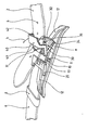
- L'invention sera mieux comprise à l'étude d'un mode de réalisation pris à titre d'exemple nullement limitatif et illustré en perspective sur la figure annexée.
- Tel que représenté sur cette figure, le fermoir dépliant comprend deux longerons 10 parallèles reliés en leurs extrémités à un dépliant droit 12 et à un dépliant gauche 12'. Les extrémités libres de ces dépliants portent un crochet 13 venant se verrouiller contre des goupilles transversales 11 installées transversalement entre les deux longerons 10. Un brin fixe 6 est fixé au dépliant gauche 12' au moyen d'une attache 20.
- A l'extrémité libre du dépliant 12 est fixée, au moyen d'un axe transversal 31, une plaque de base 30 en rotation (a) et un capot 40 tenu de part et d'autre par deux bras 43 en rotation (b). La plaque de base est sensiblement parallélépipédique aplatie et porte sur la surface supérieure, tel qu'illustré, un téton 36 situé entre les deux tiers et les trois-quarts de la ligne médiane. Le bord opposé au bord de rotation (sur la figure : le bord droit) est complété d'un onglet 32 en l'occurrence protubérant, mais pouvant également être réalisé sous la forme d'une rainure concave. Deux rainures 34 sont taillées dans les côtés latéraux proches du bord portant l'onglet.
- Le capot 40 présente une première partie en U inversé de largeur intérieure légèrement supérieure à la largeur de la base 30. Cette partie en U est tenue de part et d'autre par des bras 43 prolongeant d'un même côté les bords libres. Les extrémités de ces bras 43 sont montées en pivotement autour de l'axe 31. La hauteur des branches libres de la partie en U du capot est égale ou légèrement supérieure a la somme de l'épaisseur de la plaque de base 30 et de l'épaisseur du brin réglable 2. Tel qu'illustré, les bras 43 sont sensiblement aussi longs que la partie en U du capot 40. Par ailleurs, deux tenons 42 sont ménagés dans la face interne des branches libres de la partie en U du capot 40.
- Lorsque le fermoir dépliant est ouvert, comme illustré sur la figure, on peut alors facilement insérer le brin réglable 2 entre le capot 40 et la base 30 pour introduire l'un des orifices de réglage 4 dans le téton 36. Il est à noter que la présence des bras 43 assure une grande ouverture pour une insertion aisée du brin réglable 2. Une fois ce brin en place, il suffit de rabattre, dans un mouvement de rotation (b), le capot 40 par-dessus la base 30 jusqu'à encliqueter les tenons 42 dans leurs rainures respectives 34. L'ensemble de cette attache réglable reste toujours mobile en rotation (a). En combinaison avec un anneau 8 appartenant au brin fixe 6 dans lequel est insérée l'extrémité libre du brin réglable, cette possibilité de rotation (a) empêche toute ouverture intempestive du capot 40 par effort orthogonal sur le bracelet.
- Pour ouvrir, il suffit à IutiIisateur de placer l'ongle de son premier pouce sur l'onglet 32 et de soulever volontairement le capot 40 avec l'ongle de son second pouce.
- En alternative, le téton 36 peut aussi être fixé sur la face interne de la partie supérieure du capot 40. Egalement, le tenon 42 peut appartenir à la base 30, deux rainures 34 étant alors ménagées sous le capot 40. De manière plus sophistiquée, on peut prévoir, dans l'épaisseur de la base 30, deux billes ou tiges à extrémité arrondie émergeant hors des faces latérales sous l'action d'un ressort interne.
- En alternative, et lorsque les bras 43 du capot 40 sont directement reliés à l'axe 31 du dépliant 12, on peut sensiblement réduire, voire annuler, la longueur de ces bras 43 pour augmenter d'autant celle de la partie en U du capot 40. En effet, la hauteur des branches libres de la partie en U du capot permet toujours d'insérer sans difficulté le brin libre 2 entre le capot et le bord arrière, alors arrondi, de la plaque de base.
- Ce mécanisme de fixation réglable peut être adapté sans difficulté à un fermoir dépliable ne comportant qu'un seul dépliant 12, le brin fixe étant directement attaché à l'extrémité des longerons 10, le dépliant étant alors sensiblement aussi long que les longerons. En alternative, on peut également monter ce mécanisme de fixation réglable sur un fermoir dépliant ne comprenant qu'un seul longeron central 10, les dépliants étant alors réalisés par deux barres parallèles.
- De nombreuses améliorations peuvent être apportées à ce fermoir dépliant dans le cadre de l'invention.
Claims (8)
Applications Claiming Priority (2)
| Application Number | Priority Date | Filing Date | Title |
|---|---|---|---|
| FR9216037A FR2699796B1 (fr) | 1992-12-28 | 1992-12-28 | Fermoir dépliant pour bracelet à brin réglable. |
| FR9216037 | 1992-12-28 |
Publications (2)
| Publication Number | Publication Date |
|---|---|
| EP0607726A1 true EP0607726A1 (fr) | 1994-07-27 |
| EP0607726B1 EP0607726B1 (fr) | 1997-08-27 |
Family
ID=9437382
Family Applications (1)
| Application Number | Title | Priority Date | Filing Date |
|---|---|---|---|
| EP19930420502 Expired - Lifetime EP0607726B1 (fr) | 1992-12-28 | 1993-12-17 | Fermoir dépliant pour bracelet à brin réglable |
Country Status (5)
| Country | Link |
|---|---|
| EP (1) | EP0607726B1 (fr) |
| DE (1) | DE69313431T2 (fr) |
| ES (1) | ES2108248T3 (fr) |
| FR (1) | FR2699796B1 (fr) |
| HK (1) | HK1003026A1 (fr) |
Cited By (4)
| Publication number | Priority date | Publication date | Assignee | Title |
|---|---|---|---|---|
| WO1997029660A1 (fr) * | 1996-02-12 | 1997-08-21 | Gay Freres Vente Et Exportation S.A. | Fermoir pour bracelet |
| EP2997847A1 (fr) | 2014-09-19 | 2016-03-23 | Omega SA | Fermoir pour bracelet ou ceinture |
| EP3085265A1 (fr) | 2015-04-23 | 2016-10-26 | Omega SA | Fermoir pour bracelet |
| EP4005427A1 (fr) | 2020-11-27 | 2022-06-01 | Dress Your Body S.A. | Fermoir pour bracelet ou ceinture |
Families Citing this family (3)
| Publication number | Priority date | Publication date | Assignee | Title |
|---|---|---|---|---|
| EP0912124A1 (fr) * | 1996-06-26 | 1999-05-06 | Meliga Habillement Horloger S.A. | Systeme de fixation a rabattement pour bracelets et bracelet pourvu de ce systeme de fixation |
| JP3175603U (ja) | 2008-04-02 | 2012-05-24 | ザ・スウォッチ・グループ・マネージメント・サービシイズ・エイ ジー | 腕時計用バンド |
| CH715059A1 (de) * | 2018-05-31 | 2019-12-13 | Richemont Int Sa | Faltschliesse für Armbanduhr und Verfahren zum Nachrüsten einer solchen. |
Citations (7)
| Publication number | Priority date | Publication date | Assignee | Title |
|---|---|---|---|---|
| US1619138A (en) * | 1926-05-22 | 1927-03-01 | Kollstede George | Strap for personal wear |
| CH332930A (fr) * | 1958-04-17 | 1958-09-30 | Rolex Montres | Bracelet avec dispositif de fermeture |
| CH462516A (fr) * | 1966-10-13 | 1968-09-15 | Ikeda Hideo | Lien souple muni d'une boucle pour fixation lâche et serrée |
| CH631332A5 (en) * | 1979-10-19 | 1982-08-13 | Spillmann Sa C R | Clasp for flexible bracelet |
| GB2158145A (en) * | 1984-04-26 | 1985-11-06 | Citizen Watch Co Ltd | Watch band fastener |
| CH665536A5 (en) * | 1985-06-07 | 1988-05-31 | Cornu & Cie S A | Folding fastener for bracelet with U=shaped cover - bracelet adjustable part fits under this, tongue pivots on axle in cover and engages in hole |
| CH674447A5 (fr) * | 1987-11-19 | 1990-06-15 | G Et F Chatelain S A |
-
1992
- 1992-12-28 FR FR9216037A patent/FR2699796B1/fr not_active Expired - Fee Related
-
1993
- 1993-12-17 EP EP19930420502 patent/EP0607726B1/fr not_active Expired - Lifetime
- 1993-12-17 ES ES93420502T patent/ES2108248T3/es not_active Expired - Lifetime
- 1993-12-17 DE DE1993613431 patent/DE69313431T2/de not_active Expired - Fee Related
-
1998
- 1998-02-20 HK HK98101332A patent/HK1003026A1/xx not_active IP Right Cessation
Patent Citations (7)
| Publication number | Priority date | Publication date | Assignee | Title |
|---|---|---|---|---|
| US1619138A (en) * | 1926-05-22 | 1927-03-01 | Kollstede George | Strap for personal wear |
| CH332930A (fr) * | 1958-04-17 | 1958-09-30 | Rolex Montres | Bracelet avec dispositif de fermeture |
| CH462516A (fr) * | 1966-10-13 | 1968-09-15 | Ikeda Hideo | Lien souple muni d'une boucle pour fixation lâche et serrée |
| CH631332A5 (en) * | 1979-10-19 | 1982-08-13 | Spillmann Sa C R | Clasp for flexible bracelet |
| GB2158145A (en) * | 1984-04-26 | 1985-11-06 | Citizen Watch Co Ltd | Watch band fastener |
| CH665536A5 (en) * | 1985-06-07 | 1988-05-31 | Cornu & Cie S A | Folding fastener for bracelet with U=shaped cover - bracelet adjustable part fits under this, tongue pivots on axle in cover and engages in hole |
| CH674447A5 (fr) * | 1987-11-19 | 1990-06-15 | G Et F Chatelain S A |
Cited By (8)
| Publication number | Priority date | Publication date | Assignee | Title |
|---|---|---|---|---|
| WO1997029660A1 (fr) * | 1996-02-12 | 1997-08-21 | Gay Freres Vente Et Exportation S.A. | Fermoir pour bracelet |
| US5829104A (en) * | 1996-02-12 | 1998-11-03 | Gay Freres Vente Et Exportation S.A. | Strap clasp |
| EP2997847A1 (fr) | 2014-09-19 | 2016-03-23 | Omega SA | Fermoir pour bracelet ou ceinture |
| CN105433531A (zh) * | 2014-09-19 | 2016-03-30 | 奥米加股份有限公司 | 用于表链或带的扣钩 |
| CN105433531B (zh) * | 2014-09-19 | 2017-08-22 | 奥米加股份有限公司 | 用于表链或带的扣钩 |
| EP3085265A1 (fr) | 2015-04-23 | 2016-10-26 | Omega SA | Fermoir pour bracelet |
| US10278460B2 (en) | 2015-04-23 | 2019-05-07 | Omega Sa | Bracelet clasp |
| EP4005427A1 (fr) | 2020-11-27 | 2022-06-01 | Dress Your Body S.A. | Fermoir pour bracelet ou ceinture |
Also Published As
| Publication number | Publication date |
|---|---|
| EP0607726B1 (fr) | 1997-08-27 |
| ES2108248T3 (es) | 1997-12-16 |
| DE69313431T2 (de) | 1998-04-02 |
| FR2699796A1 (fr) | 1994-07-01 |
| FR2699796B1 (fr) | 1995-02-24 |
| HK1003026A1 (en) | 1998-09-30 |
| DE69313431D1 (de) | 1997-10-02 |
Similar Documents
| Publication | Publication Date | Title |
|---|---|---|
| CA2433290C (fr) | Bicyclette pliable | |
| EP0913106B1 (fr) | Fermoir dépliant pour bracelet | |
| EP0939019B1 (fr) | Véhicule de déplacement pour enfant en bas âge | |
| EP1908366B1 (fr) | Fermoir de bracelet | |
| EP0134595B1 (fr) | Chaussure de ski | |
| FR2510060A1 (fr) | Poussette de bebe | |
| FR2660708A1 (fr) | Piece d'assemblage pour elements longiformes. | |
| FR2635670A1 (fr) | Dispositif pour fixer provisoirement une canne a un support | |
| FR2780932A1 (fr) | Poussette pliante pour enfant, a memorisation de l'inclinaison du hamac | |
| EP0607726B1 (fr) | Fermoir dépliant pour bracelet à brin réglable | |
| FR2652753A1 (fr) | Dispositif de fixation des chaussures d'un skieur sur une planche de glisse sur neige telle qu'un monoski ou une planche de surf. | |
| FR2803318A1 (fr) | Tente modulaire | |
| EP0786274A1 (fr) | Dispositif de retenue d'une chaussure sur raquette à neige | |
| FR2882015A1 (fr) | Poussette pour enfant, a pliage parapluie | |
| FR2615377A1 (fr) | Ferrure de relevage pour un cadre horizontal | |
| EP0914781A1 (fr) | Fermoir dépliant pour bracelet | |
| FR2691342A1 (fr) | Table pliante. | |
| EP0620986B1 (fr) | Fermoir dépliant pour bracelet | |
| FR2557423A1 (fr) | Support de canne a peche | |
| FR2704591A1 (fr) | Serrure à crochet. | |
| EP1190639A1 (fr) | Pince à cheveux à mors alleges. | |
| EP1136011B1 (fr) | Bracelet articulé à flexion limitée | |
| FR2599984A1 (fr) | Dispositif de monoski | |
| WO1999017638A1 (fr) | Meuble compose d'elements assemblables | |
| CH685095A5 (fr) | Fermoir universel à boucle déployante. |
Legal Events
| Date | Code | Title | Description |
|---|---|---|---|
| PUAI | Public reference made under article 153(3) epc to a published international application that has entered the european phase |
Free format text: ORIGINAL CODE: 0009012 |
|
| AK | Designated contracting states |
Kind code of ref document: A1 Designated state(s): CH DE ES GB IT LI |
|
| 17P | Request for examination filed |
Effective date: 19940926 |
|
| 17Q | First examination report despatched |
Effective date: 19960716 |
|
| GRAG | Despatch of communication of intention to grant |
Free format text: ORIGINAL CODE: EPIDOS AGRA |
|
| GRAH | Despatch of communication of intention to grant a patent |
Free format text: ORIGINAL CODE: EPIDOS IGRA |
|
| GRAH | Despatch of communication of intention to grant a patent |
Free format text: ORIGINAL CODE: EPIDOS IGRA |
|
| GRAA | (expected) grant |
Free format text: ORIGINAL CODE: 0009210 |
|
| AK | Designated contracting states |
Kind code of ref document: B1 Designated state(s): CH DE ES GB IT LI |
|
| REG | Reference to a national code |
Ref country code: CH Ref legal event code: EP |
|
| REF | Corresponds to: |
Ref document number: 69313431 Country of ref document: DE Date of ref document: 19971002 |
|
| ITF | It: translation for a ep patent filed | ||
| REG | Reference to a national code |
Ref country code: CH Ref legal event code: NV Representative=s name: MOINAS KIEHL SAVOYE & CRONIN |
|
| REG | Reference to a national code |
Ref country code: ES Ref legal event code: FG2A Ref document number: 2108248 Country of ref document: ES Kind code of ref document: T3 |
|
| GBT | Gb: translation of ep patent filed (gb section 77(6)(a)/1977) |
Effective date: 19971126 |
|
| PLBE | No opposition filed within time limit |
Free format text: ORIGINAL CODE: 0009261 |
|
| STAA | Information on the status of an ep patent application or granted ep patent |
Free format text: STATUS: NO OPPOSITION FILED WITHIN TIME LIMIT |
|
| 26N | No opposition filed | ||
| PGFP | Annual fee paid to national office [announced via postgrant information from national office to epo] |
Ref country code: ES Payment date: 20001215 Year of fee payment: 8 |
|
| PGFP | Annual fee paid to national office [announced via postgrant information from national office to epo] |
Ref country code: DE Payment date: 20001220 Year of fee payment: 8 |
|
| REG | Reference to a national code |
Ref country code: GB Ref legal event code: IF02 |
|
| PG25 | Lapsed in a contracting state [announced via postgrant information from national office to epo] |
Ref country code: DE Free format text: LAPSE BECAUSE OF NON-PAYMENT OF DUE FEES Effective date: 20020702 |
|
| PGFP | Annual fee paid to national office [announced via postgrant information from national office to epo] |
Ref country code: GB Payment date: 20021212 Year of fee payment: 10 |
|
| PG25 | Lapsed in a contracting state [announced via postgrant information from national office to epo] |
Ref country code: ES Free format text: LAPSE BECAUSE OF NON-PAYMENT OF DUE FEES Effective date: 20021218 |
|
| PGFP | Annual fee paid to national office [announced via postgrant information from national office to epo] |
Ref country code: CH Payment date: 20021227 Year of fee payment: 10 |
|
| PG25 | Lapsed in a contracting state [announced via postgrant information from national office to epo] |
Ref country code: GB Free format text: LAPSE BECAUSE OF NON-PAYMENT OF DUE FEES Effective date: 20031217 |
|
| PG25 | Lapsed in a contracting state [announced via postgrant information from national office to epo] |
Ref country code: LI Free format text: LAPSE BECAUSE OF NON-PAYMENT OF DUE FEES Effective date: 20031231 Ref country code: CH Free format text: LAPSE BECAUSE OF NON-PAYMENT OF DUE FEES Effective date: 20031231 |
|
| REG | Reference to a national code |
Ref country code: ES Ref legal event code: FD2A Effective date: 20030113 |
|
| GBPC | Gb: european patent ceased through non-payment of renewal fee |
Effective date: 20031217 |
|
| REG | Reference to a national code |
Ref country code: CH Ref legal event code: PL |
|
| PG25 | Lapsed in a contracting state [announced via postgrant information from national office to epo] |
Ref country code: IT Free format text: LAPSE BECAUSE OF NON-PAYMENT OF DUE FEES;WARNING: LAPSES OF ITALIAN PATENTS WITH EFFECTIVE DATE BEFORE 2007 MAY HAVE OCCURRED AT ANY TIME BEFORE 2007. THE CORRECT EFFECTIVE DATE MAY BE DIFFERENT FROM THE ONE RECORDED. Effective date: 20051217 |