EP0608598B1 - Verstellbare Flüssigkeitsabgabebürstenspitze mit sekundärem Strömungsweg - Google Patents
Verstellbare Flüssigkeitsabgabebürstenspitze mit sekundärem Strömungsweg Download PDFInfo
- Publication number
- EP0608598B1 EP0608598B1 EP93306381A EP93306381A EP0608598B1 EP 0608598 B1 EP0608598 B1 EP 0608598B1 EP 93306381 A EP93306381 A EP 93306381A EP 93306381 A EP93306381 A EP 93306381A EP 0608598 B1 EP0608598 B1 EP 0608598B1
- Authority
- EP
- European Patent Office
- Prior art keywords
- tip
- tooth surface
- brush
- dental agent
- agent
- Prior art date
- Legal status (The legal status is an assumption and is not a legal conclusion. Google has not performed a legal analysis and makes no representation as to the accuracy of the status listed.)
- Expired - Lifetime
Links
- 239000000463 material Substances 0.000 claims abstract description 15
- 229940124378 dental agent Drugs 0.000 claims description 73
- 239000007767 bonding agent Substances 0.000 claims description 33
- 238000004891 communication Methods 0.000 claims description 4
- 239000004677 Nylon Substances 0.000 claims 1
- 230000004913 activation Effects 0.000 claims 1
- 229920001778 nylon Polymers 0.000 claims 1
- 238000000576 coating method Methods 0.000 abstract description 40
- 239000011248 coating agent Substances 0.000 abstract description 37
- 238000000034 method Methods 0.000 abstract description 8
- 230000008878 coupling Effects 0.000 description 9
- 238000010168 coupling process Methods 0.000 description 9
- 238000005859 coupling reaction Methods 0.000 description 9
- 239000002253 acid Substances 0.000 description 5
- 238000005530 etching Methods 0.000 description 5
- 239000000945 filler Substances 0.000 description 5
- 210000003813 thumb Anatomy 0.000 description 5
- 210000003298 dental enamel Anatomy 0.000 description 4
- 210000003811 finger Anatomy 0.000 description 4
- 239000002245 particle Substances 0.000 description 4
- 239000004033 plastic Substances 0.000 description 4
- 241000870659 Crassula perfoliata var. minor Species 0.000 description 3
- 239000000835 fiber Substances 0.000 description 3
- 238000001914 filtration Methods 0.000 description 3
- 239000011347 resin Substances 0.000 description 3
- 229920005989 resin Polymers 0.000 description 3
- 208000030507 AIDS Diseases 0.000 description 2
- 230000009471 action Effects 0.000 description 2
- 239000003795 chemical substances by application Substances 0.000 description 2
- 239000000805 composite resin Substances 0.000 description 2
- 239000004035 construction material Substances 0.000 description 2
- 239000000356 contaminant Substances 0.000 description 2
- 230000000881 depressing effect Effects 0.000 description 2
- 238000004519 manufacturing process Methods 0.000 description 2
- 230000006978 adaptation Effects 0.000 description 1
- 239000002775 capsule Substances 0.000 description 1
- 230000008859 change Effects 0.000 description 1
- 239000002131 composite material Substances 0.000 description 1
- 238000011109 contamination Methods 0.000 description 1
- 238000012864 cross contamination Methods 0.000 description 1
- 230000001627 detrimental effect Effects 0.000 description 1
- 239000011521 glass Substances 0.000 description 1
- 230000014759 maintenance of location Effects 0.000 description 1
- 239000011159 matrix material Substances 0.000 description 1
- 230000007246 mechanism Effects 0.000 description 1
- 239000002184 metal Substances 0.000 description 1
- 239000000203 mixture Substances 0.000 description 1
- 239000000178 monomer Substances 0.000 description 1
- 230000037361 pathway Effects 0.000 description 1
- 230000000704 physical effect Effects 0.000 description 1
- 238000002360 preparation method Methods 0.000 description 1
- 238000003825 pressing Methods 0.000 description 1
- 238000007639 printing Methods 0.000 description 1
- 239000012858 resilient material Substances 0.000 description 1
- 238000007789 sealing Methods 0.000 description 1
- 238000001356 surgical procedure Methods 0.000 description 1
- 208000011580 syndromic disease Diseases 0.000 description 1
- 239000011345 viscous material Substances 0.000 description 1
Images

Classifications
-
- B—PERFORMING OPERATIONS; TRANSPORTING
- B05—SPRAYING OR ATOMISING IN GENERAL; APPLYING FLUENT MATERIALS TO SURFACES, IN GENERAL
- B05C—APPARATUS FOR APPLYING FLUENT MATERIALS TO SURFACES, IN GENERAL
- B05C17/00—Hand tools or apparatus using hand held tools, for applying liquids or other fluent materials to, for spreading applied liquids or other fluent materials on, or for partially removing applied liquids or other fluent materials from, surfaces
- B05C17/005—Hand tools or apparatus using hand held tools, for applying liquids or other fluent materials to, for spreading applied liquids or other fluent materials on, or for partially removing applied liquids or other fluent materials from, surfaces for discharging material from a reservoir or container located in or on the hand tool through an outlet orifice by pressure without using surface contacting members like pads or brushes
- B05C17/00593—Hand tools of the syringe type
-
- A—HUMAN NECESSITIES
- A61—MEDICAL OR VETERINARY SCIENCE; HYGIENE
- A61C—DENTISTRY; APPARATUS OR METHODS FOR ORAL OR DENTAL HYGIENE
- A61C3/00—Dental tools or instruments
- A61C3/005—Brushes for applying dental compositions
-
- A—HUMAN NECESSITIES
- A61—MEDICAL OR VETERINARY SCIENCE; HYGIENE
- A61C—DENTISTRY; APPARATUS OR METHODS FOR ORAL OR DENTAL HYGIENE
- A61C5/00—Filling or capping teeth
- A61C5/60—Devices specially adapted for pressing or mixing capping or filling materials, e.g. amalgam presses
- A61C5/62—Applicators, e.g. syringes or guns
-
- B—PERFORMING OPERATIONS; TRANSPORTING
- B05—SPRAYING OR ATOMISING IN GENERAL; APPLYING FLUENT MATERIALS TO SURFACES, IN GENERAL
- B05C—APPARATUS FOR APPLYING FLUENT MATERIALS TO SURFACES, IN GENERAL
- B05C17/00—Hand tools or apparatus using hand held tools, for applying liquids or other fluent materials to, for spreading applied liquids or other fluent materials on, or for partially removing applied liquids or other fluent materials from, surfaces
- B05C17/005—Hand tools or apparatus using hand held tools, for applying liquids or other fluent materials to, for spreading applied liquids or other fluent materials on, or for partially removing applied liquids or other fluent materials from, surfaces for discharging material from a reservoir or container located in or on the hand tool through an outlet orifice by pressure without using surface contacting members like pads or brushes
- B05C17/00503—Details of the outlet element
- B05C17/00506—Means for connecting the outlet element to, or for disconnecting it from, the hand tool or its container
- B05C17/00513—Means for connecting the outlet element to, or for disconnecting it from, the hand tool or its container of the thread type
-
- B—PERFORMING OPERATIONS; TRANSPORTING
- B05—SPRAYING OR ATOMISING IN GENERAL; APPLYING FLUENT MATERIALS TO SURFACES, IN GENERAL
- B05C—APPARATUS FOR APPLYING FLUENT MATERIALS TO SURFACES, IN GENERAL
- B05C17/00—Hand tools or apparatus using hand held tools, for applying liquids or other fluent materials to, for spreading applied liquids or other fluent materials on, or for partially removing applied liquids or other fluent materials from, surfaces
- B05C17/005—Hand tools or apparatus using hand held tools, for applying liquids or other fluent materials to, for spreading applied liquids or other fluent materials on, or for partially removing applied liquids or other fluent materials from, surfaces for discharging material from a reservoir or container located in or on the hand tool through an outlet orifice by pressure without using surface contacting members like pads or brushes
- B05C17/00503—Details of the outlet element
- B05C17/00516—Shape or geometry of the outlet orifice or the outlet element
Definitions
- the present invention relates to apparatus for delivering a dental agent to a tooth surface. More particularly, the present invention is ideally suited for applying dental agents, such as impression material, sealing, etching, bonding, restoring and/or other treatment agents, all hereinafter collectively referred to as dental agents, to teeth surfaces.
- dental agents such as impression material, sealing, etching, bonding, restoring and/or other treatment agents, all hereinafter collectively referred to as dental agents, to teeth surfaces.
- Bonding agents play an important role in dental restorative techniques. Generally, bonding agents are applied to tooth surfaces in order to firmly attach a restoration to the tooth. When the restoration is a composite resin restoration, the composition of the bonding agent is usually that of the matrix of the composite resin.
- the enamel around a cavity preparation is etched with acid. Acid etching of enamel creates micro-irregularities on the enamel surface.
- the resin in the bonding agent is usually diluted with monomers so that it has a low viscosity which can readily penetrate into the microscopic irregularities and undercuts produced by the acid etching.
- the bonding agent is then polymerized. It is believed that when the composite restorative resin is inserted into the cavity, it will polymerize to the bonding agent present on the cavity surface. In this way, better adaptation to the enamel walls of the cavity is achieved with improved mechanical retention of the restoration.
- One device used to apply dental bonding agents is a small porous sponge or swabbing material.
- a quantity of bonding agent is applied to a transfer pad.
- a sponge is then grasped with forceps and dipped into the bonding agent.
- the wetted sponge is then rubbed across the tooth surface in order to apply the bonding agent.
- the small sponges are disposable to prevent cross-contamination.
- the sponges do not permit accurate application of the bonding agent.
- the bonding agent is applied to surrounding surfaces which do not need treatment.
- the rubbing action required to apply the bonding agent necessarily damages the fragile crystalline surface structure of the tooth formed during acid etching. Once the crystalline surface structure of the tooth is damaged, the ability to form a bond is reduced.
- Another existing device for applying bonding agent to tooth surfaces is a small disposable brush tip. Like the sponge, the brush tip must be held with forceps or some other holding device. The brush tip is then dipped into a quantity of bonding agent placed on a transfer pad.
- the brush tip is disposable.
- the brush tip does not damage the fragile crystalline structure of the tooth surface produced by acid etching.
- the brush tip must constantly be rewetted by the bonding agent during the dental procedure. This action tends to incorporate tiny microbubbles.
- the disposable brush tips used in the art usually have long bristles which do not form a fine tip. As a result, the bonding agent is often inadvertently applied to surrounding tooth surfaces.
- Yet another device for applying bonding agents to tooth surfaces is a very fine paint brush. Such a brush can apply the bonding agent to tooth surfaces with precision and detail.
- a paint brush must also be repeatedly dipped into a quantity of bonding agent during the procedure.
- a paint brush is difficult to properly sterilize and is usually nondisposable, thereby making it difficult for the dentist to maintain an aseptic environment.
- AIDS Acquired Immune Deficiency Syndrome
- a quantity of bonding agent is placed on a transfer pad so that the device can be rewetted during the surgical procedure.
- Such a technique is not only wasteful, but it exposes the bonding agent to light, air, and airborne contaminants, light being significantly detrimental as most resin-based systems used by dentists are light activated.
- an apparatus in an attempt to solve many of these problems, includes a syringe-type dispenser for holding the quantity of dental agent and a removable applicator tip having bristles at one end.
- the bristles are in communication with the syringe-type dispenser, thereby allowing the dental agent to be continuously applied to the tooth surfaces without the need to stop the dental procedure and re-wet the applicator.
- US-4997371 which forms the basis for the preamble of claim 1, discloses an apparatus for controlled delivery of a dental agent to a tooth surface comprising:
- the bristles which are held by the applicator tip are primarily held by the frictional grip which occurs at the distal end of the tip.
- This causes the bristles to act as a filter, particularly with respect to any filler particles that are contained in the dental agent.
- Such filtering may change the physical properties of the particular agent, such as a bonding agent and may make the actual bond weaker.
- Sometimes such filtering can even tend to choke off the delivery tip, preventing flow of material. In such cases, if a dentist does not use appropriate restraint, attempting to force the flow of material through a clogged tip may actually cause the tip to be blown off, expelling undesired quantities of the material into the patient's mouth.
- the fibre count is critical because if there are not enough fibres, even to the extent that there are only two or three fibres too few, the bristles will tend to push back into the tip and will not be held by the frictional grip at the distal end.
- the plastic material at the end of the tip will tend to split. This, of course, substantially complicates the manufacturing process, making it much more time consuming and tedious in order to assure very close tolerance on the fibre count in order to avoid the mentioned problems.
- the problem of filtering filler particles tends to remain.
- the present invention provides apparatus which includes a dispenser such as a syringe, squeeze bulb or the like for holding a quantity of dental agent or other coatings and a delivery tip having bristles at one end.
- the delivery tip may be curved or straight to accommodate access to the desired surface undergoing treatment.
- the bristles are slidably secured by one or more ridges that are preferably but not necessarily helical ridges.
- the spaces between the ridge or ridges form one or more channels around the bristles, and in the case of a helical ridge, the spaces between the ridge form a tapered, spiral passageway or channel (hereinafter collectively referred to as passageway) around the bristles.
- the spiral or other passageway enhances delivery of the dental agent or coating by permitting flow around the bristles and out the distal end of the tip, so that the bristles do not filter any filler particles that may be present.
- the dental agent or coating remains in the dispenser until applied directly to the surface. In this way, the dental agent or coating is not exposed to light, air, and airborne contaminants. In addition, there is no need for a transfer pad and rewetting.
- the applicator of this invention permits accurate control over the amount of dental agent or coating applied to the surface.
- the surface receives neither an excessive nor an insufficient amount of the dental agent or coating.
- the bristles permit the dental agent or coating to be applied to the surface without damaging fragile structure.
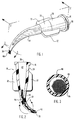
- Applicator 10 includes a syringe barrel 12 and delivery tip 14.
- Syringe barrel 12 is generally cylindrical in shape and is adapted for holding a quantity of dental agent or other coating.
- delivery tip 14 is removable. Affixed to the lower end of syringe barrel 12 is a female luer-lock coupling 18. Removable delivery tip 14 is secured to syringe barrel 12 through coupling 18. Other means may be used to couple the delivery tip 14 to the syringe barrel 12. For example, a screw fit or press-fit coupling mechanism is suitable.
- delivery tip 14 is permanently secured to the syringe barrel 12.
- the delivery tip 14 may be integrally moulded as part of the syringe barrel 12 or it may snap on irreversibly to the syringe barrel 12.
- the syringe barrel 12 could be configured to hold only a sufficient quantity of dental agent or other coating for a single application. Thereafter, the device could be discarded.
- plunger 20 Longitudinally slidable within syringe barrel 12 is plunger 20.
- Plunger 20 has at its proximal end a thumb disk 22 and at its distal end a plunger head 24.
- Plunger head 24 is constructed out of a resilient material such that its outer edge is contiguous with the inner wall of the syringe barrel 12.
- plunger head 24 is preferably constructed of a material which is non-reactive with the dental agent or coating.
- syringe barrel 12 At the proximal end of syringe barrel 12 is a pair of finger wings 26.
- conventional syringes function by placing two fingers on the finger wings 26 and depressing thumb disk 22 with the thumb
- the present invention is preferably used by placing the fingers and thumb around syringe barrel 12 and depressing thumb disk 22 by the palm of the hand. This unique method of use gives the dentist or other user greater control in applying the dental agent or coating.
- Plunger 20 longitudinally enters syringe barrel 12. As a result, plunger head 24 presses against the dental agent or coating causing it to flow out of syringe barrel 12 and through the delivery tip 14.
- the delivery tip 14 is more particularly illustrated with references to Figures 1-4, taken together.
- a male luer-lock threaded coupling 16 which is designed to mate with the corresponding female luer-lock coupling 18 of the syringe barrel 12.
- the delivery tip 28 has a cylindrical hub 28 which is tapered through conical section 30 and which joins to a nozzle 34, which may be curved as shown, or straight.
- a plurality of bristles 40 held within the curved nozzle 34 is a plurality of bristles 40, which as more particularly described hereinafter, can be used for application of the dental agent or coating using either a pin-point type application or a fanned out broad-brush type application.
- a pair of fins 32 which are provided for convenience in threading the delivery tip 14 onto the syringe barrel 12.
- the interior of the delivery tip 14 forms a passageway 42 which at its proximal end 38 is in communication with an outlet nozzle 43 (See Figure 5) from which the dental agent or coating is discharged from the interior of the syringe barrel 12 into the passageway 42 of the delivery tip 14.
- Passageway 42 could take any desired cross-sectional shape, such as circular, elliptical, or even square, rectangular or polygonal.
- the passageway 42 is tapered from the proximal end 38 of the passageway 42 to the distal end 36.
- a helical ridge 44 is formed through a portion of the passageway 42.
- the spaces 46 between the ridge 44 form a spiral passageway in which the bristles 40 are slidably secured. Because the ridge 44 is formed as a helix through the interior of the passageway 42, as shown best in Figure 4, on one side of the passageway 42 the helical ridges 44a project into the middle of the channels or spaces 46b formed between the ridges 44b on the other side of the passageway 42. Similarly, the helical ridges 44b on the other side of passageway 42 project into the middle of the spaces 44a in an alternating fashion.
- the bristles 40 to be secured by the helical ridge 44 in a helical, undulating fashion as shown in Figures 2 and 4. It has been found that by correctly dimensioning the ridge 44 in relation to the size and number of bristles 40 used in the brush, the brush slides when pushed or pulled, due to the friction by which the undulating bristles 40 are held by ridge 44.
- the ridge 44 is, for example, of from 0.10 to 0.13 mm (0.004 to 0.005 inches) high for the size bristles described below.
- the space 46 which is left around the outside of the bristles 40 forms a tapered, spiral or helical passageway which enhances the delivery of the dental agent or coating when it is dispensed by means of pressing the plunger 20 into the syringe barrel 12.
- the spiral passageway 46 actually enhances the flow of the dental agent or coating around rather than through the bristles 40 and makes the delivery of the dental agent or coating much easier than if it were forced to flow through the bristles 40.
- the spiral passageway could also be formed by forming two or more helical ridges opposing one another, such as two ridges 180° out of phase with one another.
- the passageway 46 though shown as a helical, spiralling passageway, could also take other forms.
- a plurality of straight ridges might be used or the delivery tip could even have grooves formed in the interior wall of passageway 42 so as to form straight or spiral pathways through which the dental agent or coating could flow around, but not through, the bristles so as to enhance the ease of delivery.
- the ridge 44 preferably terminates prior to the distal end 36 of the delivery tip 14.
- the bristles 40 also do not need to be frictionally held by the distal end 36 of the delivery tip 14 as in the case of the prior art type device described above since they are held by ridge 44.
- the bristle count does not need to be nearly so critical as in the case of the prior art type applicator device referenced above, thereby substantially simplifying the manufacturing procedure and substantially eliminating the problem of splitting the end of the delivery tip if two or three bristles too many are included in the brush, as well as substantially solving the problem of not holding the brush securely enough if two or three bristles too few are included in the brush.
- the dental agent or coating flows through the spiral, tapered passageway 46 around the bristles 40 rather than through the bristles 40, filler particles are not filtered out by the bristles 40 as in the case of the prior art type device and tip 14 is thus not clogged.
- substantially enhanced delivery of the dental agent or coating is accomplished by the delivery tip 14 of the present invention.
- delivery of semiviscous or viscous material which may or may not be viscous due to filler, may be virtually impossible to express using the prior art type delivery tip, but yet is easily expressed through the spiral passageway of the delivery tip of this invention.
- the bristle diameter is in the range from about 0.05 mm to about 0.15 mm (0.002 inches to about 0.005 inches), and preferably in the range from about 0.06 mm to about 0.09 mm (about 0.0025 inches to about 0.0035 inches).
- the bristles 40 typically extend beyond the distal end 36 of the delivery tip 14 a distance in the range from about 1.5 mm to about 8 mm (1/16 inch to about 5/16th inch).
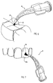
- the bristles 40 extend into the passageway 42 of the delivery tip 14 a distance sufficient to fully engage the helical ridge 44 so that the helical ridge 44 will frictionally hold the bristles 40 but yet will permit the bristles 40 to be pulled out and lengthened if the user of the device so desires in order to permit either a pin-point type application or a fanned out, broad-brush type application, as described further below in reference to Figures 6 and 7.
- the bristles extend into the passageway 42 of the delivery tip 14 in a range from about 6.3 mm to about 12.8 mm (about 1/4 inch to about 1/2 inch).
- the distance bristles 40 extend beyond the distal end 36 of delivery tip 14 may be manually adjusted by either pushing the bristles 40 further in or pulling them further out. Adjusting the length of the bristles 40 gives even greater control in applying the dental agent or coating. By pushing the bristles 40 further into delivery tip 14, the bristles are stiffer, which allows the dental agent to be worked more easily into surface irregularities such as pits and fissures, using more of a pin-point type control in applying the dental agent or coating. This is shown in conjunction with a tooth surface 50, using a pin-point type length 52 in Figure 6. By pulling the bristles 40 further out from the delivery tip 14, the user can cause the bristles 40 to fan out and more easily coat a broader surface. This is shown in conjunction with a tooth surface 50a, using a longer length 54 in Figure 7.
- the syringe barrel 12, plunger 22, coupling 18, and delivery tip 14 are preferably constructed of rigid plastic, though other suitable construction materials such as glass or metal may be used. It is also important that the syringe barrel, plunger, coupling, and delivery tip be constructed of a material which will not react with the dental agent or coating used in the syringe. In addition, the dental agent or coating should not adhere to the construction material.
- the applicator 10 may be constructed of a light-resistive material.
- the syringe barrel 12, delivery tip 14, plunger 20, and coupling 18 are preferably constructed of coloured plastic that tends to filter out light. Different coloured plastic may be used to identify the type of dental agent or coating within the syringe barrel. Alternatively, printing or other identifying markings on the syringe barrel may be used to identify the type of dental agent or coating. In addition, markings on the outer surface of the syringe barrel or plunger may be used to identify the volume of dental agent or coating used or remaining.
- the plunger within the syringe barrel permits controlled dispensing of the dental agent or coating to the surface. It will be appreciated that other means may be used to control dispensing.
- the applicator may be adapted for capsule use or for squeeze-bulb use.
Landscapes
- Health & Medical Sciences (AREA)
- Veterinary Medicine (AREA)
- Oral & Maxillofacial Surgery (AREA)
- Epidemiology (AREA)
- Life Sciences & Earth Sciences (AREA)
- Animal Behavior & Ethology (AREA)
- General Health & Medical Sciences (AREA)
- Dentistry (AREA)
- Public Health (AREA)
- Mechanical Engineering (AREA)
- Engineering & Computer Science (AREA)
- Dental Tools And Instruments Or Auxiliary Dental Instruments (AREA)
- Pens And Brushes (AREA)
- Nozzles For Electric Vacuum Cleaners (AREA)
- Coating Apparatus (AREA)
- Brushes (AREA)
Claims (16)
- Vorrichtung (10), mit der ein dentaler Wirkstoff an eine Zahnoberfläche kontrolliert abgegeben werden kann und umfaßt:Speichermittel (12), welche eine betimmte Menge des dentalen Wirkstoffes fassen;ein spitz zulaufendes Endstück (14), mit dem der dentale Wirkstoff an eine gewünschte Stelle auf der Zahnoberfläche abgegeben werden kann, wobei das proximale Ende (38) des spitz zulaufenden Endstückes mit den Speichermitteln in Verbindung steht und das spitz zulaufende Endstück Mittel umfaßt, durch welche ein erster Durchlaß (42) vom proximalen Ende des spitz zulaufende Endstückes (38) zum distalen Ende des Endtstückes (36) gebildet wird;eine Pinseleinrichtung, welche innerhalb des spitz zulaufenden Endstückes (14) befestigt ist und einen ersten Abschnitt aufweist, welcher sich genügend über das distale Ende (36) des spitz zulaufende Endstückes (14) hinaus erstreckt, sodaß der dentale Wirkstoff an die Zahnoberfläche abgegeben werden kann, und welche einen zweiten Abschnitt aufweist, der innerhalb des ersten Durchlasses (42) angeordnet ist, wobei die Pinseleinrichtung so bemessen ist, daß sie das distale Ende (36) des spitz zulaufenden Endstückes (12) im wesentlichen ausfüllt, dieses jedoch nicht verschließt;Mittel, mit denen die Abgabe des dentalen Wirkstoffes aus den Speichermitteln (12) an das distale Ende (36) des spitz zulaufenden Endstückes (14) und so der Fluß des dentalen Wirkstoffes auf die Zahnoberfläche kontrolliert werden kann;
dadurch gekennzeichnet, daßdie Vorrichtung (10) ferner Mittel umfaßt, welche innerhalb zumindest eines Abschnittes des ersten Durchlasses (42) angeordnet sind und welche einen sekundären Durchlaß (46) schaffen, durch den der dentale Wirkstoff um den zweiten Abschnitt der Pinseleinrichtung herum, jedoch nicht durch diesen hindurch, abgegeben wird, wenn der dentale Wirkstoff durch das spitz zulaufende Endstück (14) an den ersten Abschnitt der Pinseleinrichtung abgegeben wird. - Vorrichtung nach Anspruch 1, bei welcher das spitz zulaufende Endstück (14) lösbar an den Speichermitteln (12) angebracht ist.
- Vorrichtung nach Anspruch 1 oder 2, bei welcher der erste Durchlaß (42) sich vom proximalen Ende des spitz zulaufenden Endstückes (38) zum distalen Ende des spitz zulaufenden Endstückes (36) konisch verjüngt.
- Vorrichtung (10) nach Anspruch 1, mit der ein dentaler Wirkstoff an eine Zahnoberfläche kontrolliert abgegeben werden kann, bei welcherder Speicher (12) aus einem gegenüber dem dentalen Wirkstoff chemisch inerten Material hergestellt ist;das spitz zulaufende Endstück (14) gekrümmt ist, wodurch die Aufbringung des dentalen Wirkstoffes auf die Zahnoberfläche erleichtert wird, und das spitz zulaufende Endstück (14) insgesamt rohrförmig ausgebildet ist;der sekundäre Durchlaß (46) eine sich verjüngende Spirale ist;der Pinsel eine Mehrzahl von Borsten (40) umfaßt, welche verschiebbar innerhalb des spitz zulaufenden Endstückes (14) befestigt sind;die Länge des Pinsels sich ausreichend über das distale Ende des spitz zulaufende Endstückes (14) hinaus erstreckt, welches verschiebbar so eingestellt werden kann, daß der dentale Wirkstoff auf die Zahnoberfläche aufgebracht werden kann, indem je nach Wunsch entweder eine punktartige Aufbringung auf die Zahnoberfläche oder eine ausgefächerte Aufbringung auf die Zahnoberfläche in der Art eines breiten Pinsels zur Anwendung kommt; unddurch die Mittel, mit denen die Abgabe des dentalen Wirkstoffes kontrolliert wird, die Strömungsgeschwindigkeit des dentalen Wirkstoffes gesteuert werden kann.
- Vorrichtung nach einem der Ansprüche 1 bis 4, bei welcher die Mittel, durch welche der sekundäre Durchlaß (46) geschaffen wird, eine helixförmige Rippe oder Rille (44) umfassen.
- Vorrichtung nach Anspruch 5, bei welcher die Pinseleinrichtung durch die schraubenförmige Rippe oder Rille (44) verschiebbar derart befestigt ist, daß das Stück der Pinseleinrichtung, welches sich über das distale Ende des spitz zulaufende Endstückes (36) hinaus erstreckt, einstellbar ist, wodurch entweder eine punktartige Aufbringung auf die Zahnoberfläche oder eine ausgefächerte Aufbringung auf die Zahnoberfläche in der Art eines breiten Pinsels möglich ist.
- Vorrichtung nach Anspruch 6, bei welcher die helixförmige Rippe oder Rille (44) so bemessen ist, daß eine Reibung zwischen ihr und der Pinseleinrichtung geschaffen wird, und bei welcher die Pinseleinrichtung durch die schraubenförmige Rippe oder Rille (44) festgehalten wird.
- Vorrichtung nach einem der Ansprüche 1 bis 7, bei welcher der erste Durchlaß (42) sich vom proximalen Ende des spitz zulaufenden Endstückes (38) zum distalen Ende des spitz zulaufenden Endstückes (36) verjüngt.
- Vorrichtung nach Anspruch 1, mit der ein dentaler Wirkstoff an eine Zahnoberfläche kontrolliert abgegeben werden kann, bei welcherdas spitz zulaufende Endstück (14) insgesamt rohrförmig ausgebildet ist;das proximale Ende des spitz zulaufenden Endstückes (38) an dem Speicher (12) lösbar befestigt ist;das spitz zulaufende Endstück (14) gekrümmt ist, wodurch die Aufbringung des dentalen Wirkstoffes auf die Zahnoberfläche erleichtert wird;der sekundäre Durchlaß (46) eine sich verjüngende Spirale ist;die Pinseleinrichtung innerhalb des spitz zulaufenden Endstückes (14) verschiebbar befestigt ist, so daß das Stück des Pinsels, welches sich über das distale Ende des spitz zulaufenden Endstückes (36) hinaus erstreckt, verschiebbar eingestellt werden kann, wodurch der dentale Wirkstoff je nach Bedarf so auf die Zahnoberfläche aufgebracht wird, daß entweder eine punktartige Aufbringung auf die Zahnoberfläche oder eine ausgefächerte Aufbringung auf die Zahnoberfläche in der Art eines breiten Pinsels zur Anwendung kommt; unddurch die Mittel, mit denen der Fluß des dentalen Wirkstoffes kontrolliert wird, die Strömungsgeschwindigkeit des dentalen Wirkstoffes gesteuert werden kann.
- Vorrichtung nach Anspruch 9, bei welcher das spitz zulaufende Endstück (14) an dem Speicher (12) mit einem Gewinde oder durch eine Arretierung (18) vom Typ "Luer" befestigt ist.
- Vorrichtung nach Anspruch 4 oder nach Anspruch 9, bei welcher das spitz zulaufende Endstück (14) an dem Speicher (12) permanent befestigt ist.
- Vorrichtung nach einem der Ansprüche 1 bis 11, bei welcher die Speichermittel (12) ein Spritzengehäuse (12) umfassen und die Mittel, welche eine kontrollierte Abgabe ermöglichen, einen Kolben (20) umfassen, welcher innerhalb des Spritzengehäuses (12) angeordnet ist und mit dem der Fluß des dentalen Wirkstoffes gesteuert werden kann.
- Vorrichtung nach einem der Ansprüche 1 bis 12, bei welcher die Pinseleinrichtung eine Mehrzahl von Borsten (40) umfaßt, welche sich vom distalen Ende (36) des spitz zulaufenden Endstückes (14) aus über eine Strecke im Bereich von ungefähr 1,5 mm bis ungefähr 8 mm erstrecken.
- Vorrichtung nach einem der Ansprüche 1 bis 13, bei welcher die Pinseleinrichtung eine Mehrzahl von Borsten (40) umfaßt, wobei die Länge, über die sich die Borsten (40) von dem distalen Ende des spitz zulaufenden Endstückes (14) aus erstrecken, einstellbar ist.
- Vorrichtung nach einem der Ansprüche 1 bis 14, bei welcher die Pinseleinrichtung Borsten (40) umfaßt, welche aus einem weichen Nylon hergestellt sind, das einen Durchmesser im Bereich von ungefähr 0,05 mm bis ungefähr 0,15 mm hat.
- Vorrichtung nach Anspruch 1, mit welcher ein dentaler Wirkstoff an eine Zahnoberfläche kontrolliert abgegeben werden kann, bei welcherdie Vorrichtung ferner ein hohles Gehäuse (12) aufweist, welches wiederum den Speicher (12) umfaßt, wobei das Gehäuse (12) aus einem gegenüber dem Haftmittel chemisch inerten Material hergestellt ist;der Speicher (12) ausreichend opak ist, so daß eine durch Licht angeregte Aktivierung des Haftmittels verhindert wird;das spitz zulaufende Endstück (14) insgesamt rohrförmig ausgebildet ist;das proximale Ende des spitz zulaufenden Endstückes (38) an dem Speicher (12) lösbar befestigt ist;das spitz zulaufende Endstück (14) gekrümmt ist, wodurch die Aufbringung des dentalen Wirkstoffes auf die Zahnoberfläche erleichtert wird;der sekundäre Durchlaß (46) eine sich verjüngende Spirale ist;die Pinseleinrichtung eine Mehrzahl von Borsten (40) umfaßt, welche innerhalb des spitz zulaufenden Endstückes verschiebbar befestigt sind;das Stück des Pinsels, welches sich über das distale Ende des spitz zulaufenden Endstückes (36) hinaus erstreckt, verschiebbar eingestellt werden kann, so daß das dentale Haftmittel je nach Wunsch auf die Zahnoberfläche aufgebracht wird, indem entweder eine punktartige Aufbringung auf die Zahnoberfläche oder eine ausgefächerte Aufbringung auf die Zahnoberfläche in der Art eines breiten Pinsels zur Anwendung kommt, und die Mittel, mit denen die Abgabe des dentalen Wirkstoffes kontrolliert wird, einen Kolbenkopf (24) umfassen, welcher in Längsrichtung bewegt werden kann, wobei mit dem Gehäuse (12) und dem Kolben (20) die Strömungsgeschwindigkeit des Haftmittels aus dem Gehäuse (12) und auf die Zahnoberfläche gesteuert werden kann.
Applications Claiming Priority (2)
| Application Number | Priority Date | Filing Date | Title |
|---|---|---|---|
| US07/940,204 US5269684A (en) | 1992-08-31 | 1992-08-31 | Adjustable brush delivery tip with secondary flow path |
| US940204 | 1992-08-31 |
Publications (3)
| Publication Number | Publication Date |
|---|---|
| EP0608598A2 EP0608598A2 (de) | 1994-08-03 |
| EP0608598A3 EP0608598A3 (de) | 1995-01-11 |
| EP0608598B1 true EP0608598B1 (de) | 1998-12-16 |
Family
ID=25474416
Family Applications (1)
| Application Number | Title | Priority Date | Filing Date |
|---|---|---|---|
| EP93306381A Expired - Lifetime EP0608598B1 (de) | 1992-08-31 | 1993-08-12 | Verstellbare Flüssigkeitsabgabebürstenspitze mit sekundärem Strömungsweg |
Country Status (10)
| Country | Link |
|---|---|
| US (1) | US5269684A (de) |
| EP (1) | EP0608598B1 (de) |
| JP (1) | JP2721786B2 (de) |
| AT (1) | ATE174493T1 (de) |
| AU (1) | AU667375B2 (de) |
| CA (1) | CA2101137C (de) |
| DE (1) | DE69322612T2 (de) |
| DK (1) | DK0608598T3 (de) |
| ES (1) | ES2127791T3 (de) |
| GR (1) | GR3029698T3 (de) |
Cited By (2)
| Publication number | Priority date | Publication date | Assignee | Title |
|---|---|---|---|---|
| USD456078S1 (en) | 1999-04-27 | 2002-04-23 | Dentsply Research & Development Corp. | Applicator tip for dental materials |
| US7959370B2 (en) | 2002-09-27 | 2011-06-14 | Dentsply International, Inc. | Packaged dental composition |
Families Citing this family (118)
| Publication number | Priority date | Publication date | Assignee | Title |
|---|---|---|---|---|
| US5816804A (en) | 1996-01-19 | 1998-10-06 | Ultradent Products, Inc. | Fiber-ended open orifice delivery tip |
| US6282013B1 (en) | 1997-04-30 | 2001-08-28 | Lasermed, Inc. | System for curing polymeric materials, such as those used in dentistry, and for tailoring the post-cure properties of polymeric materials through the use of light source power modulation |
| US6008264A (en) | 1997-04-30 | 1999-12-28 | Laser Med, Inc. | Method for curing polymeric materials, such as those used in dentistry, and for tailoring the post-cure properties of polymeric materials through the use of light source power modulation |
| WO1999021505A1 (en) | 1997-10-29 | 1999-05-06 | Bisco, Inc. | Dental composite light curing system |
| US6116900A (en) * | 1997-11-17 | 2000-09-12 | Lumachem, Inc. | Binary energizer and peroxide delivery system for dental bleaching |
| US6200134B1 (en) | 1998-01-20 | 2001-03-13 | Kerr Corporation | Apparatus and method for curing materials with radiation |
| US20040241614A1 (en) * | 1998-04-13 | 2004-12-02 | Goldberg A. Jon | Prefabricated components for dental appliances |
| US6202897B1 (en) | 1998-08-25 | 2001-03-20 | 3M Innovative Properties Company | Unit dose liquid dispensing and packaging for dental application |
| DE69932080T2 (de) * | 1998-12-07 | 2007-01-18 | Stick Tech Oy | Eine vorrichtung zur verwendung insbesondere der verstärkung von zähnen oder dentalen prothesevorrichtungen |
| US6083002A (en) * | 1999-02-04 | 2000-07-04 | 3M Innovative Properties Co. | Cartridge for dispensing liquid compositions |
| US6157661A (en) * | 1999-05-12 | 2000-12-05 | Laserphysics, Inc. | System for producing a pulsed, varied and modulated laser output |
| US6095813A (en) * | 1999-06-14 | 2000-08-01 | 3M Innovative Properties Company | Method for applying a dental composition to tooth structure |
| DE19934235A1 (de) * | 1999-07-21 | 2000-10-19 | Transcoject Gmbh | Instrument zum Austragen |
| US6238120B1 (en) | 2000-04-07 | 2001-05-29 | Phillip E. Mark | Fluid applicator |
| CA2422337C (en) * | 2000-09-21 | 2009-12-08 | Dentsply International Inc. | Mixing tip for dispensing materials |
| DE60129346T2 (de) | 2000-10-13 | 2007-10-31 | Dentsply International Inc. | Misch-, Aufbewahrungs- und Abgabevorrichtung für mehrere Komponenten |
| US7040893B2 (en) | 2000-10-30 | 2006-05-09 | Ultradent Products, Inc. | Fiber-covered dental delivery instruments |
| US6537239B2 (en) * | 2001-05-14 | 2003-03-25 | Phillip Mark | Insert for a nozzle of a flow through liquid applicator and combination thereof |
| US6390817B1 (en) * | 2001-05-15 | 2002-05-21 | Steven Jensen | Fiber tipped dental substance applicator |
| EP1392194A1 (de) * | 2001-06-04 | 2004-03-03 | Dentsply International, Inc. | Pipette für dentalmaterial |
| CA2484748A1 (en) * | 2002-05-08 | 2003-11-20 | Dentsply International Inc. | Capped syringe tip |
| EP1505950B1 (de) * | 2002-05-23 | 2007-12-05 | Dentsply International, Inc. | Zahnlack gegen karies |
| US20040038174A1 (en) * | 2002-08-25 | 2004-02-26 | Dentsply Research & Development Corp. | Applicator for liquid dental materials |
| DE10254409A1 (de) * | 2002-11-21 | 2004-06-03 | Ernst Mühlbauer Gmbh & Co. Kg | Vorrichtung zum Mischen und Ausbringen von Mehrkomponentenmassen |
| US20040122377A1 (en) * | 2002-12-19 | 2004-06-24 | Fischer Dan E. | Syringe delivery tip adapted to provide controlled flow rate |
| US7147468B2 (en) | 2002-12-31 | 2006-12-12 | Water Pik, Inc. | Hand held oral irrigator |
| US7198623B2 (en) * | 2003-01-10 | 2007-04-03 | Ultradent Products, Inc. | Fiber-coated dental infusor systems and methods of use |
| US6913464B2 (en) * | 2003-01-20 | 2005-07-05 | Denbur, Inc. | Composition applicator tip |
| JP3493359B1 (ja) * | 2003-03-20 | 2004-02-03 | 宣美 辛島 | イオン泳動式治療装置 |
| US6749356B1 (en) | 2003-06-03 | 2004-06-15 | Northrop Grumman Corporation | Touch-up coating applicator assembly for remote locations |
| US20050082317A1 (en) * | 2003-10-21 | 2005-04-21 | Coll John V. | Angled caulk nozzle |
| US20050100390A1 (en) * | 2003-11-07 | 2005-05-12 | Juanita Jantz | Paint dispensing system and apparatus |
| US20050154343A1 (en) * | 2004-01-14 | 2005-07-14 | Mohinder Singh | Soft tip applicator for relieving mouth pain |
| USD530010S1 (en) | 2004-03-17 | 2006-10-10 | Water Pik, Inc. | Base for an oral implement |
| US7179085B2 (en) * | 2004-11-16 | 2007-02-20 | Denteque | Apparatus for dispensing dental solutions |
| USD574952S1 (en) | 2006-02-24 | 2008-08-12 | Water Pik, Inc. | Water jet handle |
| USD565175S1 (en) | 2006-02-24 | 2008-03-25 | Water Pik, Inc. | Water jet base |
| US20070203439A1 (en) | 2006-02-24 | 2007-08-30 | Water Pik, Inc. | Water jet unit and handle |
| US20070284400A1 (en) * | 2006-06-09 | 2007-12-13 | Paul Richard Pierson | Package for a dental material |
| US7670141B2 (en) | 2006-07-07 | 2010-03-02 | Water Pik, Inc. | Oral irrigator |
| US9872557B2 (en) * | 2006-12-06 | 2018-01-23 | Cao Group, Inc. | Delivery tip for flowable materials |
| USD802120S1 (en) | 2007-02-27 | 2017-11-07 | Water Pik, Inc. | Tip for oral irrigator |
| KR100892766B1 (ko) * | 2008-09-11 | 2009-04-15 | 이달호 | 골조직 이식을 위한 주사기용 본 인퓨저 |
| US8808317B2 (en) * | 2008-11-06 | 2014-08-19 | Carl Braunagel | Apparatus for cleaning a nasal cavity |
| US20100190132A1 (en) | 2009-01-28 | 2010-07-29 | Water Pik, Inc. | Oral irrigator tip |
| US10258442B2 (en) | 2009-03-20 | 2019-04-16 | Water Pik, Inc. | Oral irrigator appliance with radiant energy delivery for bactericidal effect |
| IL197761A0 (en) * | 2009-03-23 | 2009-12-24 | Moshe Zalsman | Capsule for mixing together two flowable materials, and kits including such capsules, particularly useful in dentistry |
| US9066777B2 (en) | 2009-04-02 | 2015-06-30 | Kerr Corporation | Curing light device |
| US9072572B2 (en) | 2009-04-02 | 2015-07-07 | Kerr Corporation | Dental light device |
| US8066510B2 (en) * | 2009-04-14 | 2011-11-29 | Phillip Phung-I Ho | Dental agent applicator |
| US9061096B2 (en) | 2009-12-16 | 2015-06-23 | Water Pik, Inc. | Powered irrigator for sinus cavity rinse |
| USD629884S1 (en) | 2009-12-16 | 2010-12-28 | Water Pik, Inc. | Powered irrigator for sinus cavity rinse |
| US8337473B2 (en) * | 2010-07-16 | 2012-12-25 | Christian Javier Zino Gutierrez | Substance dispenser, especially for medical or cosmetic treatment |
| WO2012044298A1 (en) * | 2010-09-30 | 2012-04-05 | Dentsply International Inc. | Mixing tip for dental materials |
| USD670373S1 (en) | 2010-12-16 | 2012-11-06 | Water Pik, Inc. | Powered irrigator for sinus cavity rinse |
| US8790035B2 (en) | 2011-03-18 | 2014-07-29 | The Wooster Brush Company | Flow-thru liquid coating applicator |
| USD707350S1 (en) | 2012-10-11 | 2014-06-17 | Water Pik, Inc. | Handheld water flosser |
| WO2014059362A2 (en) | 2012-10-11 | 2014-04-17 | Water Pik, Inc. | Interdental cleaner using water supply |
| DE102013201460A1 (de) * | 2013-01-30 | 2014-07-31 | Transcodent GmbH & Co. KG | Composite-Kapsel und Verfahren zum Ausbringen einer Dentalmasse |
| USD717427S1 (en) | 2013-03-14 | 2014-11-11 | Water Pik, Inc. | Handle for water flosser |
| US9642677B2 (en) | 2013-03-14 | 2017-05-09 | Water Pik, Inc. | Oral irrigator with massage mode |
| USD788907S1 (en) | 2013-03-14 | 2017-06-06 | Water Pik, Inc. | Water flosser base unit with reservoir lid |
| USD714929S1 (en) | 2013-03-14 | 2014-10-07 | Water Pik, Inc. | Base for water flosser |
| USD725770S1 (en) | 2013-03-14 | 2015-03-31 | Water Pik, Inc. | Reservoir for water flosser |
| US9980793B2 (en) | 2013-11-27 | 2018-05-29 | Water Pik, Inc. | Oral hygiene system |
| ES2718685T3 (es) | 2013-11-27 | 2019-07-03 | Water Pik Inc | Irrigador bucal con interruptor de pausa deslizante |
| CN203693808U (zh) | 2013-12-12 | 2014-07-09 | 洁碧有限公司 | 牙科用喷水器 |
| US9427079B2 (en) | 2014-02-28 | 2016-08-30 | Young Microbrush, Llc | Dental dispensing tip and method of manufacturing |
| USD772397S1 (en) | 2014-12-01 | 2016-11-22 | Water Pik, Inc. | Oral irrigator with a charging device |
| CN205586102U (zh) | 2014-12-01 | 2016-09-21 | 洁碧有限公司 | 防水无线口腔冲洗器 |
| USD772396S1 (en) | 2014-12-01 | 2016-11-22 | Water Pik, Inc. | Handheld oral irrigator |
| USD780908S1 (en) | 2015-11-03 | 2017-03-07 | Water Pik, Inc. | Handheld oral irrigator |
| USD822196S1 (en) | 2016-01-14 | 2018-07-03 | Water Pik, Inc. | Oral irrigator |
| USD782656S1 (en) | 2016-01-25 | 2017-03-28 | Water Pik, Inc. | Oral irrigator |
| USD794773S1 (en) | 2016-07-19 | 2017-08-15 | Water Pik, Inc. | Oral irrigator |
| USD796028S1 (en) | 2016-07-19 | 2017-08-29 | Water Pik, Inc. | Oral irrigator |
| US10835356B2 (en) | 2016-01-25 | 2020-11-17 | Water Pik, Inc. | Swivel assembly for oral irrigator handle |
| USD783809S1 (en) | 2016-01-25 | 2017-04-11 | Water Pik, Inc. | Oral irrigator handle |
| USD786422S1 (en) | 2016-01-25 | 2017-05-09 | Water Pik, Inc. | Oral irrigator |
| USD804018S1 (en) | 2016-07-19 | 2017-11-28 | Water Pik, Inc. | Base for an oral irrigator |
| USD802747S1 (en) | 2016-07-19 | 2017-11-14 | Water Pik, Inc. | Reservoir for oral irrigator |
| USD819956S1 (en) | 2016-01-25 | 2018-06-12 | Water Pik, Inc. | Kit bag |
| KR102072661B1 (ko) | 2016-01-25 | 2020-02-03 | 워터 피크 인코포레이티드 | 형상 인자가 감소된 구강 세정기 |
| USD804016S1 (en) | 2016-02-05 | 2017-11-28 | Water Pik, Inc. | Handheld oral irrigator |
| USD783810S1 (en) | 2016-02-22 | 2017-04-11 | Water Pik, Inc. | Handle for an oral irrigator |
| USD809650S1 (en) | 2016-02-22 | 2018-02-06 | Water Pik, Inc. | Oral irrigator |
| CA3016031C (en) | 2016-03-02 | 2020-07-07 | Water Pik, Inc. | Actuation assembly for an oral irrigator |
| USD802119S1 (en) | 2016-03-02 | 2017-11-07 | Water Pik, Inc. | Oral irrigator |
| USD782657S1 (en) | 2016-03-02 | 2017-03-28 | Water Pik, Inc. | Oral irrigator handle |
| USD807822S1 (en) | 2016-07-19 | 2018-01-16 | Water Pik, Inc. | Power supply cartridge |
| USD809651S1 (en) | 2016-07-19 | 2018-02-06 | Water Pik, Inc. | Combination base and reservoir for an oral irrigator |
| USD840022S1 (en) | 2016-12-15 | 2019-02-05 | Water Pik, Inc. | Oral irrigator handle |
| USD832418S1 (en) | 2016-12-15 | 2018-10-30 | Water Pik, Inc. | Oral irrigator base |
| USD829886S1 (en) | 2016-12-15 | 2018-10-02 | Water Pik, Inc. | Oral irrigator base |
| USD839409S1 (en) | 2016-12-15 | 2019-01-29 | Water Pik, Inc. | Oral irrigator unit |
| USD822826S1 (en) | 2016-12-15 | 2018-07-10 | Water Pik, Inc. | Oral irrigator base |
| USD833600S1 (en) | 2016-12-15 | 2018-11-13 | Water Pik, Inc. | Oral irrigator reservoir |
| USD834180S1 (en) | 2016-12-15 | 2018-11-20 | Water Pik, Inc. | Oral irrigator base |
| KR102576326B1 (ko) | 2016-12-15 | 2023-09-08 | 워어터 피이크, 인코포레이티드 | 자기 부착부를 갖는 구강 세척기 |
| USD833000S1 (en) | 2016-12-15 | 2018-11-06 | Water Pik, Inc. | Oral irrigator unit |
| USD832419S1 (en) | 2016-12-15 | 2018-10-30 | Water Pik, Inc. | Oral irrigator unit |
| USD822825S1 (en) | 2016-12-15 | 2018-07-10 | Water Pik, Inc. | Oral irrigator unit |
| USD840023S1 (en) | 2016-12-15 | 2019-02-05 | Water Pik, Inc. | Oral irrigator reservoir |
| USD867579S1 (en) | 2016-12-15 | 2019-11-19 | Water Pik, Inc. | Oral irrigator unit |
| USD832420S1 (en) | 2016-12-15 | 2018-10-30 | Water Pik, Inc. | Oral irrigator base |
| USD825741S1 (en) | 2016-12-15 | 2018-08-14 | Water Pik, Inc. | Oral irrigator handle |
| EP3554420B1 (de) | 2016-12-15 | 2021-05-19 | Water Pik, Inc. | Pausenventil und schwenkanordnungen für den griff einer mundspülvorrichtung |
| USD833602S1 (en) | 2017-02-06 | 2018-11-13 | Water Pik, Inc. | Oral irrigator base |
| USD833601S1 (en) | 2017-02-06 | 2018-11-13 | Water Pik, Inc. | Oral irrigator |
| USD829887S1 (en) | 2017-02-06 | 2018-10-02 | Water Pik, Inc. | Oral irrigator reservoir |
| USD868243S1 (en) | 2018-03-16 | 2019-11-26 | Water Pik, Inc. | Oral irrigator tip |
| USD877324S1 (en) | 2018-05-17 | 2020-03-03 | Water Pik, Inc. | Oral irrigator handle |
| CN109393716A (zh) * | 2018-11-08 | 2019-03-01 | 上海耀佳医疗器械有限公司 | 一次性注塑成型毛刷针头 |
| USD888936S1 (en) | 2019-02-22 | 2020-06-30 | Water Pik, Inc. | Cordless water flosser |
| USD889636S1 (en) | 2019-02-22 | 2020-07-07 | Water Pik, Inc. | Water flosser |
| KR102163013B1 (ko) * | 2020-02-12 | 2020-10-07 | 대구보건대학교산학협력단 | 보철물 제작용 바셀린 압출 도포장치 |
| USD966498S1 (en) | 2020-09-15 | 2022-10-11 | Water Pik, Inc. | Oral irrigator |
| USD1016274S1 (en) | 2021-02-16 | 2024-02-27 | Water Pik, Inc. | Oral irrigator |
Family Cites Families (60)
| Publication number | Priority date | Publication date | Assignee | Title |
|---|---|---|---|---|
| US1711516A (en) * | 1929-05-07 | Plunger bhavino brush | ||
| US374026A (en) * | 1887-11-29 | Syringe | ||
| US392006A (en) * | 1888-10-30 | Dental tool | ||
| US762603A (en) * | 1903-12-26 | 1904-06-14 | Randall Faichney Co | Hypodermic syringe. |
| US870573A (en) * | 1904-04-12 | 1907-11-12 | Charles G Myers | Instrument for introducing liquid medicament into teeth. |
| US833044A (en) * | 1906-03-13 | 1906-10-09 | Claudius Ash Sons & Company 1905 Ltd | Dental instrument. |
| US860555A (en) * | 1906-11-21 | 1907-07-16 | William Clay Middaugh | Dental-syringe attachment. |
| US977825A (en) * | 1910-01-08 | 1910-12-06 | George N Murphy | Surgical instrument. |
| US1115561A (en) * | 1911-09-18 | 1914-11-03 | Parke Davis & Co | Syringe. |
| US1164430A (en) * | 1915-04-26 | 1915-12-14 | Robert B Thurman | Syringe. |
| US1245153A (en) * | 1916-03-24 | 1917-11-06 | Lee Surgico Dental M F G Co Inc | Dental instrument. |
| US1438064A (en) * | 1921-11-16 | 1922-12-05 | Johnson & Johnson | Dental pellet |
| US1573224A (en) * | 1924-03-31 | 1926-02-16 | Park N Condit | Liquid applicator |
| US1711352A (en) * | 1928-01-12 | 1929-04-30 | George A Jeffreys | Tracheal-swab syringe |
| US1908403A (en) * | 1932-04-04 | 1933-05-09 | Carrie L Budde | Surgical instrument |
| US2170222A (en) * | 1935-10-28 | 1939-08-22 | Oscar A Strauss | Instrument for vaginal treatment |
| US2090354A (en) * | 1936-05-14 | 1937-08-17 | Abraham E Massman | Combined medicine dropper and swab |
| US2104651A (en) * | 1936-06-30 | 1938-01-04 | Carl C Hoffman Inc | Nail polish applicator |
| US2100157A (en) * | 1937-07-09 | 1937-11-23 | Harry H Chandler | Swab |
| US2643655A (en) * | 1949-09-19 | 1953-06-30 | Mckay Augus Conrad | Hypodermic and other syringes or drenchers |
| US2754590A (en) * | 1954-09-20 | 1956-07-17 | Cohen Milton Joseph | Container for toothache remedy |
| US2902035A (en) * | 1958-10-10 | 1959-09-01 | Newell D Hartley | Syringe |
| US3270743A (en) * | 1963-05-29 | 1966-09-06 | Leeming Miles Pharmaccuticals | Hypodermic injection syringe |
| US3175242A (en) * | 1963-07-15 | 1965-03-30 | Kamondy Charles | Means for applying paint in long narrow strips |
| US3234918A (en) * | 1964-01-06 | 1966-02-15 | L & C Hardtmuth Inc | Writing implement with cartridge |
| US3369543A (en) * | 1965-03-30 | 1968-02-20 | Deron Inc | Medicinal applicators |
| US3434209A (en) * | 1965-05-12 | 1969-03-25 | Bernard Weissman | Method for building superstructures on dentition |
| US3462840A (en) * | 1965-06-03 | 1969-08-26 | Irving A Ellman | Dental dispenser with calcium hydroxide paste |
| US3346147A (en) * | 1966-08-18 | 1967-10-10 | Brunswick Corp | Dental compound syringe |
| US3337095A (en) * | 1966-08-29 | 1967-08-22 | Jacob P Marbach | Syringe for automatic proportioning |
| US3512526A (en) * | 1967-11-24 | 1970-05-19 | Sol B Fielding | Sponge sheath for douche tip |
| US3519364A (en) * | 1968-02-02 | 1970-07-07 | Andrew Truhan | Applicator |
| US3572337A (en) * | 1968-12-26 | 1971-03-23 | George J Schunk | Syringe for oral administration of medicine |
| US3581399A (en) * | 1969-08-08 | 1971-06-01 | Centrix Inc | Composite resin filling syringe and technique |
| US3587575A (en) * | 1969-09-15 | 1971-06-28 | Lichtenstein Eric Stefan | Self-contained, moving needle syringe with hydraulic safety lock |
| US3759259A (en) * | 1971-03-08 | 1973-09-18 | A Truhan | Medicator with frangible seal |
| US3760503A (en) * | 1972-05-18 | 1973-09-25 | Dentipressions Inc | Disposable mixing syringe |
| US3792699A (en) * | 1972-05-30 | 1974-02-19 | Medex Inc | Disposable swab unit |
| CH557178A (de) * | 1972-08-10 | 1974-12-31 | Siemens Ag | Geraet fuer die zufuehrung von medikamenten. |
| US3910706A (en) * | 1974-01-07 | 1975-10-07 | Trisa Buerstenfabrik Ag | Cartridge for liquid or pasty dentifrice |
| US3918435A (en) * | 1974-01-24 | 1975-11-11 | Miles Lab | Transport swab tube |
| US3896552A (en) * | 1974-03-18 | 1975-07-29 | Ez Floss | Dental instrument |
| US3938898A (en) * | 1974-04-05 | 1976-02-17 | Jack Reitknecht | Swab applicator with adapter chuck and closure |
| FR2288495A1 (fr) * | 1974-07-11 | 1976-05-21 | Pitois Jacqueline | Pinceau applicateur coude pouvant etre imbibe a volonte par pression |
| US3924623A (en) * | 1974-11-04 | 1975-12-09 | Marion Health And Safety Inc | Tip for applicator swab |
| CH580427A5 (de) * | 1975-07-28 | 1976-10-15 | Contraves Ag | |
| US4143428A (en) * | 1976-12-16 | 1979-03-13 | Cohen I Kelman | Saline fill of silicone prosthesis during mammaplasty augmentation |
| US4225254A (en) * | 1977-03-17 | 1980-09-30 | Holberg Steven E | Surgical scrub system |
| US4157709A (en) * | 1977-05-09 | 1979-06-12 | Ovutime, Inc. | Probe for obtaining cervical mucus and process thereof |
| US4243035A (en) * | 1979-06-18 | 1981-01-06 | Barrett Howard G | Syringe with integral swab |
| US4578055A (en) * | 1979-07-25 | 1986-03-25 | Fischer Dan E | Controlled diffusion medicament applicator |
| US4941873A (en) * | 1979-07-25 | 1990-07-17 | Ultradent Products, Inc. | Controlled diffusion medicament applicator |
| US4318403A (en) * | 1980-07-24 | 1982-03-09 | Sneider Vincent R | Foldable nozzle syringe |
| US4329990A (en) * | 1980-08-07 | 1982-05-18 | Sneider Vincent R | Expanding swab applicator |
| US4551100A (en) * | 1982-06-07 | 1985-11-05 | Ultradent, Inc. | Method of preparing gingival area for dental crowns |
| US4522593A (en) * | 1983-07-07 | 1985-06-11 | Fischer Dan E | Knitted gingival retraction cord |
| US4813871A (en) * | 1987-09-25 | 1989-03-21 | Friedman Stephen J | Dental viscous material dispenser |
| US4997371A (en) * | 1988-06-22 | 1991-03-05 | Honda Giken Kogyo Kabushiki Kaisha | Dental agent applicator |
| US5052927A (en) * | 1988-10-24 | 1991-10-01 | Discko John Jr | Syringe and disposable capsule with cannula for use therewith |
| JPH07100071B2 (ja) * | 1990-01-16 | 1995-11-01 | 東洋製罐株式会社 | 乾式殺菌装置及びその方法 |
-
1992
- 1992-08-31 US US07/940,204 patent/US5269684A/en not_active Expired - Lifetime
-
1993
- 1993-07-20 AU AU42051/93A patent/AU667375B2/en not_active Expired
- 1993-07-22 CA CA002101137A patent/CA2101137C/en not_active Expired - Fee Related
- 1993-08-12 DK DK93306381T patent/DK0608598T3/da active
- 1993-08-12 EP EP93306381A patent/EP0608598B1/de not_active Expired - Lifetime
- 1993-08-12 AT AT93306381T patent/ATE174493T1/de not_active IP Right Cessation
- 1993-08-12 ES ES93306381T patent/ES2127791T3/es not_active Expired - Lifetime
- 1993-08-12 DE DE69322612T patent/DE69322612T2/de not_active Expired - Fee Related
- 1993-08-31 JP JP5215895A patent/JP2721786B2/ja not_active Expired - Fee Related
-
1999
- 1999-03-16 GR GR990400782T patent/GR3029698T3/el unknown
Cited By (2)
| Publication number | Priority date | Publication date | Assignee | Title |
|---|---|---|---|---|
| USD456078S1 (en) | 1999-04-27 | 2002-04-23 | Dentsply Research & Development Corp. | Applicator tip for dental materials |
| US7959370B2 (en) | 2002-09-27 | 2011-06-14 | Dentsply International, Inc. | Packaged dental composition |
Also Published As
| Publication number | Publication date |
|---|---|
| DK0608598T3 (da) | 1999-08-23 |
| EP0608598A3 (de) | 1995-01-11 |
| DE69322612D1 (de) | 1999-01-28 |
| DE69322612T2 (de) | 1999-07-29 |
| JP2721786B2 (ja) | 1998-03-04 |
| ES2127791T3 (es) | 1999-05-01 |
| US5269684A (en) | 1993-12-14 |
| AU4205193A (en) | 1994-03-10 |
| JPH06169941A (ja) | 1994-06-21 |
| CA2101137C (en) | 1996-04-02 |
| GR3029698T3 (en) | 1999-06-30 |
| ATE174493T1 (de) | 1999-01-15 |
| AU667375B2 (en) | 1996-03-21 |
| EP0608598A2 (de) | 1994-08-03 |
| CA2101137A1 (en) | 1994-03-01 |
Similar Documents
| Publication | Publication Date | Title |
|---|---|---|
| EP0608598B1 (de) | Verstellbare Flüssigkeitsabgabebürstenspitze mit sekundärem Strömungsweg | |
| US4997371A (en) | Dental agent applicator | |
| US5816804A (en) | Fiber-ended open orifice delivery tip | |
| US6328715B1 (en) | Unit dose low viscosity material dispensing system | |
| US4578055A (en) | Controlled diffusion medicament applicator | |
| US4941873A (en) | Controlled diffusion medicament applicator | |
| US5692642A (en) | Fluid dispenser adapter and method of use | |
| US7198623B2 (en) | Fiber-coated dental infusor systems and methods of use | |
| US6382972B1 (en) | Cushioned, fiber-covered dental delivery tips | |
| CA2004728A1 (en) | Method and apparatus for dispensing a fluid substance | |
| CA2427577A1 (en) | Cushioned, fiber-covered dental applicators | |
| JPS60194962A (ja) | 歯科用注射器 | |
| WO2007134237A2 (en) | Syringe delivery tip including an enlarged flocked wing element adjacent a distal delivery end | |
| EP0141083A1 (de) | Vorrichtung zum Abgeben von fliessfähigem Material | |
| EP1256389A2 (de) | Leicht ladbares System zur Ausgabe von Doseneinheiten eines niedrigviskosen Stoffes | |
| JP2904521B2 (ja) | 往復歯科工具 | |
| WO1989012428A1 (en) | Dental agent applicator | |
| US6390817B1 (en) | Fiber tipped dental substance applicator | |
| US20210153637A1 (en) | Clinical dispenser and applicator | |
| US4343418A (en) | Dispenser for dental sealant | |
| CA2242817C (en) | Fiber-ended open orifice delivery tip | |
| US20140106298A1 (en) | Clinical Dispenser and Applicator | |
| US6159009A (en) | Dental amalgam carrier with replaceable sleeves and cartridges | |
| US20040038174A1 (en) | Applicator for liquid dental materials | |
| EP1427347A2 (de) | Applikator für flüssige dentalmaterialien |
Legal Events
| Date | Code | Title | Description |
|---|---|---|---|
| PUAI | Public reference made under article 153(3) epc to a published international application that has entered the european phase |
Free format text: ORIGINAL CODE: 0009012 |
|
| AK | Designated contracting states |
Kind code of ref document: A2 Designated state(s): AT BE CH DE DK ES FR GB GR IE IT LI LU MC NL PT SE |
|
| PUAL | Search report despatched |
Free format text: ORIGINAL CODE: 0009013 |
|
| AK | Designated contracting states |
Kind code of ref document: A3 Designated state(s): AT BE CH DE DK ES FR GB GR IE IT LI LU MC NL PT SE |
|
| RHK1 | Main classification (correction) |
Ipc: A61C 5/00 |
|
| 17P | Request for examination filed |
Effective date: 19950301 |
|
| 17Q | First examination report despatched |
Effective date: 19970801 |
|
| GRAG | Despatch of communication of intention to grant |
Free format text: ORIGINAL CODE: EPIDOS AGRA |
|
| GRAG | Despatch of communication of intention to grant |
Free format text: ORIGINAL CODE: EPIDOS AGRA |
|
| GRAH | Despatch of communication of intention to grant a patent |
Free format text: ORIGINAL CODE: EPIDOS IGRA |
|
| GRAH | Despatch of communication of intention to grant a patent |
Free format text: ORIGINAL CODE: EPIDOS IGRA |
|
| GRAA | (expected) grant |
Free format text: ORIGINAL CODE: 0009210 |
|
| AK | Designated contracting states |
Kind code of ref document: B1 Designated state(s): AT BE CH DE DK ES FR GB GR IE IT LI LU MC NL PT SE |
|
| REF | Corresponds to: |
Ref document number: 174493 Country of ref document: AT Date of ref document: 19990115 Kind code of ref document: T |
|
| REG | Reference to a national code |
Ref country code: CH Ref legal event code: EP |
|
| REF | Corresponds to: |
Ref document number: 69322612 Country of ref document: DE Date of ref document: 19990128 |
|
| REG | Reference to a national code |
Ref country code: IE Ref legal event code: FG4D |
|
| ITF | It: translation for a ep patent filed | ||
| PG25 | Lapsed in a contracting state [announced via postgrant information from national office to epo] |
Ref country code: PT Free format text: LAPSE BECAUSE OF FAILURE TO SUBMIT A TRANSLATION OF THE DESCRIPTION OR TO PAY THE FEE WITHIN THE PRESCRIBED TIME-LIMIT Effective date: 19990316 |
|
| REG | Reference to a national code |
Ref country code: CH Ref legal event code: NV Representative=s name: E. BLUM & CO. PATENTANWAELTE |
|
| ET | Fr: translation filed | ||
| REG | Reference to a national code |
Ref country code: ES Ref legal event code: FG2A Ref document number: 2127791 Country of ref document: ES Kind code of ref document: T3 |
|
| PG25 | Lapsed in a contracting state [announced via postgrant information from national office to epo] |
Ref country code: LU Free format text: LAPSE BECAUSE OF NON-PAYMENT OF DUE FEES Effective date: 19990812 Ref country code: IE Free format text: LAPSE BECAUSE OF NON-PAYMENT OF DUE FEES Effective date: 19990812 |
|
| REG | Reference to a national code |
Ref country code: DK Ref legal event code: T3 |
|
| PLBI | Opposition filed |
Free format text: ORIGINAL CODE: 0009260 |
|
| PLBF | Reply of patent proprietor to notice(s) of opposition |
Free format text: ORIGINAL CODE: EPIDOS OBSO |
|
| 26 | Opposition filed |
Opponent name: VOCO GMBH Effective date: 19990916 |
|
| NLR1 | Nl: opposition has been filed with the epo |
Opponent name: VOCO GMBH |
|
| PG25 | Lapsed in a contracting state [announced via postgrant information from national office to epo] |
Ref country code: MC Free format text: LAPSE BECAUSE OF NON-PAYMENT OF DUE FEES Effective date: 20000229 |
|
| PLBF | Reply of patent proprietor to notice(s) of opposition |
Free format text: ORIGINAL CODE: EPIDOS OBSO |
|
| PLBF | Reply of patent proprietor to notice(s) of opposition |
Free format text: ORIGINAL CODE: EPIDOS OBSO |
|
| REG | Reference to a national code |
Ref country code: IE Ref legal event code: MM4A |
|
| PGFP | Annual fee paid to national office [announced via postgrant information from national office to epo] |
Ref country code: AT Payment date: 20010720 Year of fee payment: 9 |
|
| PGFP | Annual fee paid to national office [announced via postgrant information from national office to epo] |
Ref country code: GR Payment date: 20010731 Year of fee payment: 9 |
|
| PLBL | Opposition procedure terminated |
Free format text: ORIGINAL CODE: EPIDOS OPPC |
|
| REG | Reference to a national code |
Ref country code: GB Ref legal event code: IF02 |
|
| PLBM | Termination of opposition procedure: date of legal effect published |
Free format text: ORIGINAL CODE: 0009276 |
|
| STAA | Information on the status of an ep patent application or granted ep patent |
Free format text: STATUS: OPPOSITION PROCEDURE CLOSED |
|
| 27C | Opposition proceedings terminated |
Effective date: 20011008 |
|
| NLR2 | Nl: decision of opposition | ||
| PGFP | Annual fee paid to national office [announced via postgrant information from national office to epo] |
Ref country code: SE Payment date: 20020718 Year of fee payment: 10 |
|
| PGFP | Annual fee paid to national office [announced via postgrant information from national office to epo] |
Ref country code: DK Payment date: 20020719 Year of fee payment: 10 |
|
| PGFP | Annual fee paid to national office [announced via postgrant information from national office to epo] |
Ref country code: NL Payment date: 20020722 Year of fee payment: 10 |
|
| PGFP | Annual fee paid to national office [announced via postgrant information from national office to epo] |
Ref country code: BE Payment date: 20020808 Year of fee payment: 10 |
|
| PG25 | Lapsed in a contracting state [announced via postgrant information from national office to epo] |
Ref country code: AT Free format text: LAPSE BECAUSE OF NON-PAYMENT OF DUE FEES Effective date: 20020812 |
|
| PGFP | Annual fee paid to national office [announced via postgrant information from national office to epo] |
Ref country code: ES Payment date: 20020909 Year of fee payment: 10 |
|
| PG25 | Lapsed in a contracting state [announced via postgrant information from national office to epo] |
Ref country code: GR Free format text: LAPSE BECAUSE OF NON-PAYMENT OF DUE FEES Effective date: 20030305 |
|
| PG25 | Lapsed in a contracting state [announced via postgrant information from national office to epo] |
Ref country code: SE Free format text: LAPSE BECAUSE OF NON-PAYMENT OF DUE FEES Effective date: 20030813 Ref country code: ES Free format text: LAPSE BECAUSE OF NON-PAYMENT OF DUE FEES Effective date: 20030813 |
|
| PGFP | Annual fee paid to national office [announced via postgrant information from national office to epo] |
Ref country code: CH Payment date: 20030825 Year of fee payment: 11 |
|
| PG25 | Lapsed in a contracting state [announced via postgrant information from national office to epo] |
Ref country code: BE Free format text: LAPSE BECAUSE OF NON-PAYMENT OF DUE FEES Effective date: 20030831 |
|
| PG25 | Lapsed in a contracting state [announced via postgrant information from national office to epo] |
Ref country code: DK Free format text: LAPSE BECAUSE OF NON-PAYMENT OF DUE FEES Effective date: 20030901 |
|
| BERE | Be: lapsed |
Owner name: *ULTRADENT PRODUCTS INC. Effective date: 20030831 |
|
| PG25 | Lapsed in a contracting state [announced via postgrant information from national office to epo] |
Ref country code: NL Free format text: LAPSE BECAUSE OF NON-PAYMENT OF DUE FEES Effective date: 20040301 |
|
| REG | Reference to a national code |
Ref country code: DK Ref legal event code: EBP |
|
| EUG | Se: european patent has lapsed | ||
| NLV4 | Nl: lapsed or anulled due to non-payment of the annual fee |
Effective date: 20040301 |
|
| PGFP | Annual fee paid to national office [announced via postgrant information from national office to epo] |
Ref country code: GB Payment date: 20040804 Year of fee payment: 12 |
|
| PGFP | Annual fee paid to national office [announced via postgrant information from national office to epo] |
Ref country code: FR Payment date: 20040819 Year of fee payment: 12 |
|
| PG25 | Lapsed in a contracting state [announced via postgrant information from national office to epo] |
Ref country code: LI Free format text: LAPSE BECAUSE OF NON-PAYMENT OF DUE FEES Effective date: 20040831 Ref country code: CH Free format text: LAPSE BECAUSE OF NON-PAYMENT OF DUE FEES Effective date: 20040831 |
|
| REG | Reference to a national code |
Ref country code: ES Ref legal event code: FD2A Effective date: 20030813 |
|
| REG | Reference to a national code |
Ref country code: CH Ref legal event code: PL |
|
| PG25 | Lapsed in a contracting state [announced via postgrant information from national office to epo] |
Ref country code: GB Free format text: LAPSE BECAUSE OF NON-PAYMENT OF DUE FEES Effective date: 20050812 |
|
| GBPC | Gb: european patent ceased through non-payment of renewal fee |
Effective date: 20050812 |
|
| PG25 | Lapsed in a contracting state [announced via postgrant information from national office to epo] |
Ref country code: FR Free format text: LAPSE BECAUSE OF NON-PAYMENT OF DUE FEES Effective date: 20060428 |
|
| REG | Reference to a national code |
Ref country code: FR Ref legal event code: ST Effective date: 20060428 |
|
| PGFP | Annual fee paid to national office [announced via postgrant information from national office to epo] |
Ref country code: IT Payment date: 20060831 Year of fee payment: 14 |
|
| PGFP | Annual fee paid to national office [announced via postgrant information from national office to epo] |
Ref country code: DE Payment date: 20061002 Year of fee payment: 14 |
|
| PG25 | Lapsed in a contracting state [announced via postgrant information from national office to epo] |
Ref country code: DE Free format text: LAPSE BECAUSE OF NON-PAYMENT OF DUE FEES Effective date: 20080301 |
|
| PG25 | Lapsed in a contracting state [announced via postgrant information from national office to epo] |
Ref country code: IT Free format text: LAPSE BECAUSE OF NON-PAYMENT OF DUE FEES Effective date: 20070812 |