EP0609224B1 - Drehventil - Google Patents
Drehventil Download PDFInfo
- Publication number
- EP0609224B1 EP0609224B1 EP19920914504 EP92914504A EP0609224B1 EP 0609224 B1 EP0609224 B1 EP 0609224B1 EP 19920914504 EP19920914504 EP 19920914504 EP 92914504 A EP92914504 A EP 92914504A EP 0609224 B1 EP0609224 B1 EP 0609224B1
- Authority
- EP
- European Patent Office
- Prior art keywords
- disk
- liquid
- cavity
- control valve
- port
- Prior art date
- Legal status (The legal status is an assumption and is not a legal conclusion. Google has not performed a legal analysis and makes no representation as to the accuracy of the status listed.)
- Expired - Lifetime
Links
Images


Classifications
-
- C—CHEMISTRY; METALLURGY
- C02—TREATMENT OF WATER, WASTE WATER, SEWAGE, OR SLUDGE
- C02F—TREATMENT OF WATER, WASTE WATER, SEWAGE, OR SLUDGE
- C02F1/00—Treatment of water, waste water, or sewage
- C02F1/42—Treatment of water, waste water, or sewage by ion-exchange
-
- Y—GENERAL TAGGING OF NEW TECHNOLOGICAL DEVELOPMENTS; GENERAL TAGGING OF CROSS-SECTIONAL TECHNOLOGIES SPANNING OVER SEVERAL SECTIONS OF THE IPC; TECHNICAL SUBJECTS COVERED BY FORMER USPC CROSS-REFERENCE ART COLLECTIONS [XRACs] AND DIGESTS
- Y10—TECHNICAL SUBJECTS COVERED BY FORMER USPC
- Y10T—TECHNICAL SUBJECTS COVERED BY FORMER US CLASSIFICATION
- Y10T137/00—Fluid handling
- Y10T137/8593—Systems
- Y10T137/86493—Multi-way valve unit
- Y10T137/86718—Dividing into parallel flow paths with recombining
- Y10T137/86726—Valve with bypass connections
Definitions
- This invention relates to a rotary flow control valve having use in a multiple cycle liquid treatment apparatus, and more particularly to an improved rotary flow control valve that automatically starts and stops different cycles of the liquid treatment apparatus.
- Water softening apparatus using ion exchange resin particles must be regularly regenerated with brine in order to restore or maintain the water hardness removing capacity of the resin particles.
- the flow control valve for such apparatus must accurately control the volume and velocity of liquid flowing through the resin particles in the treatment tank and in the brining system during each of four or more cycles.
- Automatic water softening apparatus used in single family residences has to be capable of operating under a wide range of pressure, flow, and hardness conditions, as are typically found in such residences.
- Prior flow control valves, usable under such a wide range of conditions were often unduly complicated and difficult to service because they had a large number of moving parts. Also, such prior valves were not capable of being used with different types of liquid treatment equipment, for instance filters which require high flow rates during their backwash cycle.
- the rotary flow control valve of this invention is an improvement on the liquid flow control valve set forth in U.S. Patent No. 4,136,032, entitled, Liquid Treatment Apparatus, issued January 23, 1979. Valves manufactured in accordance with the teaching of that patent have served well.
- Another object is to provide a rotary flow control valve usable with different types of multi-cycle liquid treatment apparatus such as domestic or commercial water softener units, and liquid filters which is capable of successfully operating under a wide range of non-constant flow and pressure conditions.
- Another object is to provide a multi-cycle liquid flow control valve which has a low internal pressure drop over a wide range of flow volumes.
- Another object is to provide a rotary flow control valve having a small number of moving parts, and which does not require precise adjustments for proper operation.
- Another object is to provide a five cycle rotary liquid flow control valve having a pair of rotatable slotted disks wherein essentially all components of the valve can be made by injection molding of plastic.
- Another object is to provide a slotted rotatable disk for a liquid flow control valve that holds a gasket in its groove as a slot passes over the gasket, even during sudden increases in liquid flow or pressure.
- Another object is to provide mounting arrangements on the valve housing for an aspirator and for a turbine for measuring water flow.
- Still another object is to provide a multi-cycle rotary liquid flow control valve for water treatment equipment that is durable, easy to repair and maintain with a minimum number of tools if any, relatively low cost, and which does not possess shortcomings found in similar prior art valves.
- a liquid flow control valve having a housing with aligned cylindrical cavities, which are separated by a web having a central bore therethrough and passages therethrough radially spaced from said central bore.
- a pair of radially extending ports are formed in the sidewall of the housing, with one of the ports extending into one of the cylindrical cavities, and the other port extending into the other of the cylindrical cavities.
- the present invention provides a rotary flow control valve for use with a container enclosing a liquid treating material, the control valve comprising; a housing having; a first cylindrical cavity formed by a first cylindrical sidewall, an untreated liquid inlet port extending from the first cylindrical sidewall, a second cylindrical cavity formed by a second cylindrical sidewall, a treated liquid outlet port extending from the second cylindrical sidewall, the cavities being axially aligned, a bore connecting the cavities on their central axes.
- a passage spaced radially outwardly from the bore also connecting the cavities, first and second holes in the housing connecting the first and second cavities respectively to the inside of the container a regenerant liquid inlet port and a regenerant liquid refill port for connection to a regenerant liquid tank, and a waste outlet port; a pair of separate, rotatable, slotted circular disk assemblies each including a circular disk having a smooth flat face, a first of the smooth flat faces sealingly engaging a surface of the first cavity, and a second of the smooth flat faces sealingly engaging a corresponding surface of the second cavity, and hollow tubular coupling means extending through the bore and connecting the disks to each other; and a drive motor for rotating the disks in unison so as to selectively align various slots in each disk with, or to block, the cavities, bore, passage and holes, such that the direction of liquid flow in the valve is changed and controlled by rotation of the disks, wherein, when the disk assemblies are in a position to effect a regeneration and slow rinse cycle for the liquid treating material, the disks
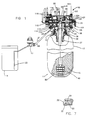
- a liquid flow control valve 10 that automatically starts and stops the various cycles of a conventional multiple cycle ion exchange water softening apparatus 11 which is typically installed in a home.
- Housing 30 of valve 10 is attached by two clamp ring sections 12 to the top of a conventional pressure tank 13 enclosing beads 15 of ion exchange resin.
- the clamp ring sections are coupled by two clips (not shown).
- a conventional regenerant solution or brine tank 16 and an aspirator suction nozzle 17 are directly connected to a regenerant liquid refill port 18 and to a regenerant liquid inlet port 20.
- Tank 16 may contain one or more liquid flow pipes 23 and other conventional components, such as a float controlled shut-off valve (not shown).
- Valve 10 is connected to a pressurized source of hard water through an untreated or raw liquid inlet port 24 and to a service supply conduit through a treated liquid outlet port 25.
- Housing 30 has a first cylindrical cavity 31 at its right end which includes inlet port 24 on its back side wall, and a second cylindrical cavity 32 on its left end which includes outlet port 25 on its back side wall as viewed in FIG. 1.
- the ports 24 and 25 are best shown in FIG. 2.
- Cavities 31 and 32 are axially aligned and are connected on their central axis by a cylindrical bore 33.
- a passage or bypass port 35 spaced radially outwardly from bore 33 also connects cavities 31 and 32.
- the entrance to passage 35 in cavity 31 is only one-third as wide as its outlet into cavity 32, as may be seen in FIGS. 3 and 4. As best shown in FIG.
- a first opening 36 in housing 30 connects cavity 31 to the inside of tank 13 through a conventional perforated liquid distributor 37 provided at the top of the tank, and a second opening 39 connects cavity 32 to the inside of tank 13 through a conventional perforated liquid collector 40 that terminates near the bottom 50 of the tank and is coaxial at its upper end with the distributor 37.
- An axially extended flow passage 51 in the side of housing 30 connects cavity 32 to regenerant liquid fill port 18.
- Blind recesses 52, 53, 126, 127, 128, and 129 extend into cavity 31, and blind recesses 54, 55, 130 and 131 extend into cavity 32.
- the blind recesses are not part of the flow paths through the valve, but rather are formed so as to conserve material from which housing 30 is formed.
- An interconnected group of grooves 57 surrounds passage 35, bore 33, opening 36, and blind recesses 52, 53, 126, 127, 128 and 129 in end surface 58 of cavity 31.
- a resilient unitary O-ring gasket 59 is placed within the group of grooves 57.
- Another interconnected group of grooves 61 surrounds passage 35, bore 33, opening 39, blind recesses 54, 55, 130 and 131, and flow passage 51 in the end surface 62 of cavity 32.
- a resilient unitary O-ring gasket 63 is placed within the group of grooves.
- disk assembly 41 includes a circular disk 43 which has a flat smooth face 67 which seals against the exposed surface of the O-ring 59.
- disk assembly 42 includes a circular disk 45 which has a flat smooth face 68 which seals against the exposed surface of the O-ring 63.
- Disk assembly 42 includes a formed member 65 which has an open-ended, integral, hollow, circular, tubular projection 70 extending from face 67.
- Disk assembly 42 includes a formed member 66 which has a corresponding open-ended integral, hollow, circular, tubular projection 71 extending from face 68.
- the end of projection 70 is notched at 72 and 73, and the end of projection 71 is notched at 74 and 75, such that these notches may mate so as to provide a slip-fit that enables projections 70 and 71 to be coupled to each other inside of bore 33.
- the notches are formed such that may be mated in only one position, thereby insuring the correct orientation of the disk assemblies 41 and 42 with respect to each other.
- Projections 70 and 71 are axially aligned with each other and with waste port 27.
- the components of circular disk assemblies 41 and 42 are formed from at least two different materials.
- the circular disks 43 and 44 are preferably formed by molding an unfilled polyphenaloxide such as "Novel".
- the unfilled polyphenaloxide is preferred, since it provided a smooth, slick surface for engagement with the O-rings 59 and 93.
- the remaining components of the assemblies 41 and 42 are preferably formed of a glass filled polyphenaloxide such as "Novel". The glass filled polyphenaloxide is preferred because of the greater strength it provides.
- slots 77, 78, 79 and 80 formed in the face 67 of disk 43 are connected to the inside of projection 70 by a passageway 82 that is defined by a blister 83 extending above the opposite face of the disk and completely enclosing the slots.
- two slots 85 and 86 formed in the face 68 of disk 45 are connected to the inside of projection 71 by a passageway 87 that is defined by a blister 88 extending above the opposite face of the disk and completely enclosing the slots.
- a slot 90, relatively wide in the radial direction, in formed member 65 of disk assembly 41 is spanned by a bridge 91 having a flat smooth surface 92 in the same plane as the disk face 67.
- a slot 95, relatively wide in the radial direction, in formed member 66 of disk assembly 42 is spanned by a bridge 96 having a flat smooth surface 97 in the same plane as the disk face 68.
- Disk assembly 42 also has a small cylindrical through hole 140.
- Two small openings 141 and 142 formed in the face 68 of the disk 45 are interconnected by an internal channel provided in formed member 66.
- Surface 92 of bridge 91 presses against the portion of gasket 59 surrounding hole 36 and prevents gasket 59 from being pulled out of groove 57 by sudden increases in liquid flow, or pressure changes, or frictional drags that occur as wide slot 95 passes over hole 39.
- a hollow circular journal 100 secured to blister 83 rotatably supports disk assembly 41 in a bearing hole 101 of end cap 28.
- a circular hole 102 through journal 100 is axially aligned between projection 70 and waste port 27.
- End cap 28 is removably attached to housing 30 by two substantially semi-circular clamps 103 and two clips 125, as are shown in FIG. 31.
- a thrust spring 104 compressed between a shoulder 105 on journal 100 and end cap 28 urges flat smooth face 67 of disk 43 against the exposed surface of O-ring gasket 59.
- a conventional flow control washer 106 is positioned between the journal 100 and the nipple 26 in port 27.
- a second flow washer 137 is located over opening 123 of disk assembly 12.
- a coupling bar 109 projects from the outer surface of the blister 88.
- a circular journal 110 has a slot 111 in its inner face for receiving and coupling with bar 109. Journal 110 is rotatably received in a bearing hole 112 in an end cap 113, and thus provides support for disk assembly 42.
- a conventional electric gear motor assembly 116 turns a gear 134 in a predetermined rotational angle sequence as controlled by an electronic control circuit.
- the gear 134 is coupled to journal 110 and thus provides the force which rotates disks 65 and 66 in unison so as to selectively align various slots in each disk with, or to block, the cavities, channel, passages and bores for varying time periods during which the direction of liquid flow in the apparatus is changed and controlled.
- a drive member 152 which includes the driven gear 134 and a cam 154 is secured to the journal 110 to drive the disk assemblies 41 and 42.
- the journal 110 is provided with an irregular shape, such that a similarly irregularly shaped cup 156 provided on the drive member 52 will fit over the journal 110 in only one position, so as to ensure the proper orientation of the cam 154 with respect to the disk assemblies 41 and 42.
- An end cap 158 is provided on the cup 156 such that a fastener 160, such as a screw, may be used to secure the drive member 152 to the journal 110.
- the gear motor 110 is secured to the bosses 162 provided on the end cap 113.
- a pinion gear on the gear motor 116 as shown in FIG. 1 engages the driven gear 134 to rotate the drive member 152 in a counter-clockwise direction as viewed in FIG. 38.
- a pair of micro switches 164 and 166 are secured on the end cap 113 in such a position that their actuating members are engaged by the cam 154.
- Five equally spaced cam surfaces 168, 170, 172, 174 and 176 are positioned to engage the actuator of micro switch 164.
- An additional cam surface 178 is provided adjacent to cam surface 176 in a position to engage the actuator of micro switch 166.
- the control circuit Upon first energizing the control circuit for the water softening apparatus 11, the control circuit will energize the motor to rotate the gear 134 to the position wherein the actuator of switch 166 passed the position shown in FIG. 41 to the position shown in FIG. 42, wherein the actuator of switch 166 falls into the cam surface 178, but wherein the actuator of switch 164 has not yet reached the cam surface 176. This is considered a home position, from which the five cycles controlled by the valve 110 can be initiated.
- the control circuit will energize the motor such that it will rotate to the clockwise direction in the position wherein the actuator of switch 164 will fall within the cam surface 176.
- the drive motor will then be de-energized for a period of time determined by the control circuit, after which it will again be energized such that the motor will again rotate the drive member 152 in the counter-clockwise direction until the actuator of switch 164 falls within the cam surface 174.
- the actuation of the micro switch 164 the drive motor will be de-energized by the control circuit.
- the motor will remain de-energized for a period of time determined by the control circuit.
- the motor will again be energized and the motor will again drive the gear in the counterclockwise direction until the actuated switch 164 falls into the cam surface 172.
- the drive member 152 continues to be rotated through the several cycles of the control valve until the position is reached wherein the actuator switch 166 is again engaged in the cam surface 178 to provide an indication to the control circuit that the end of the cycle has been reached.
- the micro switches 164 and 166 are shown with their actuators engaged in the cam surfaces 176 and 178 in the "home" position.
- Two substantially semi-circular clamps 103 and two clips 125 as shown in FIG. 31 through 33 hold end caps 28 and 113 on housing 30.
- the same clamps 103 and clips 125 are used to secure the valve housing 30 to the pressure tank 13.
- the semi-circular clamps 103 and clips 125 are provided with a groove 180 on their inner surface which engages flanges provided on the housings and on the end caps and the pressure tank 13.
- the groove 180 is formed such that as the clamp rings are drawn together by the clips 125, the grooves will force the flanges toward each other.
- a first end of each clamp 103 is provided with a first type of securing means 182, while the other end is provided with a second type of securing means 184.
- the clips 125 have a aperture 186 therein, a first portion of which has a first wider opening 188 and the second portion of which has a narrower opening 190. These openings are provided in a bottom wall 192 in the aperture 186.
- the second type of securing means 184 is passed through the opening 188 such that a lip 194 formed thereon engages the surface of the bottom wall 192.
- a tab 194 on the clip is pushed toward the clamp 103, such that it passes through the opening 190 until it reaches the position shown in FIG. 34, wherein projections 196 on the sides of the securing means 182 engage the surface of the bottom wall 192.
- the second clip is installed in a similar fashion.
- the application of an appropriate amount of force to the tab 194 will cause the wall 192 to pass over the projections 196 such that the clips can be removed.
- O-rings should be employed in appropriately placed grooves to seal the joints of the parts of the valve 10, and the valve housing 30 and end caps 28 and 113 may be made by conventional injection molding of a plastic which has a low surface friction, such as partially glass-filled acetal.
- Outlet port 25 is provided with a well 139 which opens to the outside.
- Well 139 is provided to receive a magnetic sensor.
- a standard nozzle-venturi aspirator 17 is directly secured over ports 18 and 20 as shown in FIG. 32 by a clip 150 which is received in a pocket 152 formed in the housing 30, and a notch 154 from in the mounting portion of the aspirator 17.
- the nozzle venturi aspirator is connected by a single tube 44 to the liquid flow pipes 23 in the brine tank 16.
- Valve 10 will operate in the following manner to automatically control liquid flow in apparatus 10 during a five cycle water softening sequence.
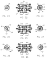
- the disks 65 and 66 are positioned essentially as shown in FIGS. 16-18.
- Slot 90 in disk 65 is aligned with hole 36 in cavity 31 and slot 93 in disk 66 is aligned with hole 39 in cavity 32.
- the slots 120, 121 and slots 77-80 under blister 83 in disk 65 do not face any open liquid flow paths through cavity 31.
- the slots 122 and 123 and slots 85 and 86 under blister 88 in disk 66 do not face any open liquid flow paths through cavity 32.
- All of the hard water entering cavity 31 through port 24 leaves through slot 90 and enters distributor 37 through hole 36.
- the hard water is softened as it flows downwardly through the bed of ion exchange resin beads 15.
- Soft water enters the lower end of collector 40 and flows up into cavity 32 through aligned hole 39 and slot 95. From cavity 32, the soft water flows to service through port 25.
- the next cycle provides for regenerant tank refill.
- the disks 65 and 66 are rotated essentially to the positions shown in FIGS. 19-21.
- Slot 120 in disk 65 is aligned with hole 36, and none of the other slots in disk 65 face an open flow path.
- Slot 122 in disk 66 is aligned with hole 39, and slot 95 is aligned with passage 51 and angled passage 144.
- Angled passage 51 connects to the refill port 18.
- Angled passage 144 connects to the inlet port 20. None of the other slots in disk 66 face an open flow path.
- Hard water entering through port 24 passes through aligned slot 120 and hole 36, and is then softened as described above. The soft water enters cavity 32 through aligned hole 39 and slot 122 and passes to service through port 25.
- Soft water in cavity 32 also flows through slot 95 into angled passage 151 and into angled passage 144. The water from both passages then flows through the aspirator 17 and through the tube 44 into the brine tank 16.
- the volume of soft water flowing into tank 16 may be controlled in a conventional manner by a float-controlled shut-off valve.
- the next cycle provides for regeneration and slow rinse of the resin bed.
- the disks 65 and 66 are rotated to essentially the positions shown in FIGS. 22-24. Slots 79-80 beneath blister 83 on disk 65 are aligned with hole 36 and slot 120 is aligned with passage 35. The other slots in disk 65 do not face an open flow path. Slot 95 in disk 66 is also aligned with passage 35 and slot 141 is aligned with angled passage 144. Slot 142 is aligned with hole 39 and slot 140 is aligned with angled passage 51. None of the other slots in disk 66 face an open flow path. Thus disk 66 blocks direct flow from cavity 32 to hole 39, and blister 83 on disk 65 blocks direct flow from cavity 31 to hole 36.
- Passageway 82 in blister 83 connects hole 36 to the inside of projection 70 and thus provides a flow path through hole 102 to waste port 27.
- Hard water in cavity 31 flows through slot 90 into passage 35 and then through slot 95 into cavity 32. During this cycle only hard water is available for service through port 25.
- Hard water from cavity 32 flows through angled passage 51, port 18 (indicated in phantom in FIG. 22), to aspirator nozzle 17. This water flow through nozzle 17 creates a suction that draws regenerant solution out of tank 16 in conventional manner. Since nozzle 17 is constricted, the volume of flow is relatively small.
- Hole 39 is in essence vented to atmospheric pressure through a path traceable in sequence through collector 40, container 13, distributor 37, hole 36, slots 77-80, passageway 82, projection 70, hole 102, and waste port 27.
- the regenerant solution flows through line 21, 44, aspirator 17, and port 20 into disk channel 143, hole 39, and then through collector 40 into the bottom of the bed of ion exchange resin beads 15.
- the regenerant solution passes slowly upwardly through the bed of beads 15 and restores their hardness removing capacity.
- the spent regenerant solution enters distributor 37 and flows into hole 36, and then through slots 77-80, passageway 82, projection 70, and hole 102 to waste port 27. From waste port 27, the spent regenerant solution flows to a sewer or other disposal destination.
- regenerant solution flow After a predetermined volume of regenerant solution has been drawn out of tank 16, the conventional valving therein terminates regenerant solution flow to aspirator 17, but the flow of water through angled passage 51 continues to follow the path described above and thus slowly rinses the regenerant solution from the bed of resin beads 15 in container 13.
- the next cycle provides for backwashing of the resin bed.
- the disks 65 and 66 are rotated to essentially the positions shown in FIGS. 25-27.
- the slots under blister 83 on disk 65 are still aligned with hole 36 and slot 90 is still aligned with passage 35.
- the other slots in disk 65 do not face an open flow path.
- Slot 123 in disk 66 is aligned with hole 39 and slot 95 is aligned with passage 35.
- the other slots in disk 66 do not face an open flow path.
- blister 83 continues to block flow from cavity 31 to hole 36, flow continues from cavity 31 through slot 90 into passage 35 and through slot 95 into cavity 32.
- Hard water is provided for service through port 25.
- the greatly increased flow of backwash water agitates the bed of resin beads 15 and tumbles them around in tank 13. This vigorous action cleans the beads and dislodges foreign matter which is washed away with the dirty water through distributor 37, hole 36, passageway 82, projection 70, hole 102 and out through waste port 27.
- the water flows rapidly downwardly into collector 40, packing beads 15 into a tight bed against the bottom of tank 13 while continuing to rinse the beads. From collector 40 the rinse water flows in sequence through hole 39 and slots 85 and 86 into passageway 87, projections 71 and 70, hole 102 and is discharged through waste port 27. This completes the five cycle water softening process. Disks 65 and 66 are next rotated to the position shown in FIGS. 16-18 to resume a service cycle.
- the direction, volume, and sequence of liquid flow in the treatment apparatus can be varied by changing the size and location of slots in the rotating disks 65 and 66 and the position and size of the passages, holes, ports, etc. in housing 30. Cycles can also be added or eliminated in this manner.
- the volume and direction of liquid flow can be controlled so effectively with the control valve of this invention, that it can be used with commercial type water softeners and also with liquid filters.
Landscapes
- Life Sciences & Earth Sciences (AREA)
- Hydrology & Water Resources (AREA)
- Engineering & Computer Science (AREA)
- Environmental & Geological Engineering (AREA)
- Water Supply & Treatment (AREA)
- Chemical & Material Sciences (AREA)
- Organic Chemistry (AREA)
- Multiple-Way Valves (AREA)
- Treatment Of Water By Ion Exchange (AREA)
- Taps Or Cocks (AREA)
- Sliding Valves (AREA)
- Check Valves (AREA)
- Massaging Devices (AREA)
Claims (8)
- Drehventil zur Verwendung mit einem Behälter, der ein Flüssigkeitsbehandlungsmaterial umschließt, wobei das Ventil folgendes umfaßt:a. ein Gehäuse (30) mit:einem ersten zylindrischen Hohlraum (31), der von einer ersten zylindrischen Seitenwand gebildet wird,einer Einlaßöffnung (24) für unbehandelte Flüssigkeit, die von der ersten zylindrischen Seitenwand wegverläuft,einem zweiten zylindrischen Hohlraum (32), der von einer zweiten zylindrischen Seitenwand gebildet wird,einer Auslaßöffnung (25) für behandelte Flüssigkeit, die von der zweiten zylindrischen Seitenwand wegverläuft, wobei die Hohlräume axial ausgerichtet sind,einer Bohrung (33), die die Hohlräume auf ihren Mittelachsen verbindet,einem Kanal (35), der von der Bohrung radial auswärts beabstandet ist und ebenfalls die Hohlräume verbindet,einem ersten und einem zweiten Loch (36, 39) in dem Gehäuse, die den ersten und den zweiten Hohlraum jeweils mit der Innenseite des Behälters (13) verbinden,einer Einlaßöffnung (20) für Regenerierungsflüssigkeit und einer Nachfüllöffnung (18) für Regenerierungsflüssigkeit für den Anschluß an einen Regenerierungsflüssigkeitstank (16), undeiner Abproduktauslaßöffnung (27);b. ein Paar separater, rotierbarer, geschlitzter, kreisförmiger Scheibenbaugruppen (41, 42), die jeweils folgendes umfassen: eine kreisförmige Scheibe (43, 45) mit einer glatten ebenen Fläche, wobei eine erste der glatten ebenen Flächen dichtend in eine Oberfläche des ersten Hohlraums eingreift und eine zweite der glatten ebenen Flächen dichtend in eine entsprechende Oberfläche des zweiten Hohlraums eingreift, und eine hohle röhrenförmige Kupplung (70, 71), die durch die Bohrung verläuft und die Scheiben miteinander verbindet; undc. einen Antriebsmotor (110) zum einstimmigen Drehen der Scheiben, um verschiedene Schlitze in jeder Scheibe selektiv auf die Hohlräume, die Bohrung, den Kanal und die Löcher auszurichten oder um diese zu blockieren, so daß die Richtung des Flüssigkeitsstroms in dem Ventil durch Drehen der Scheiben geändert und gesteuert wird,
wobei sich, wenn sich die Scheibenbaugruppen (41, 42) in einer Position befinden, um einen Regenerierungs- und langsamen Spülzyklus für das Flüssigkeitsbehandlungsmaterial zu bewirken, die Scheiben (43, 45) in einer Position befinden, in der ein Schlitz in der ersten Scheibe zwischen dem ersten Hohlraum (31) und dem Kanal (35) ausgerichtet ist, ein Schlitz in der zweiten Scheibe (45) zwischen dem zweiten Hohlraum (32) und dem Kanal ausgerichtet ist und ein weiterer Schlitz in der zweiten Scheibe zwischen dem zweiten Hohlraum (32) und der Nachfüllöffnung (18) für Regenerierungsflüssigkeit ausgerichtet ist, so daß unbehandelte Flüssigkeit von dem ersten Hohlraum durch den Kanal in den zweiten Hohlraum, durch die Auslaßöffnung und durch die Nachfüllöffnung strömt, die Einlaßöffnung (20) für Regenerierungsflüssigkeit über einen inneren Scheibenbaugruppenkanal mit dem zweiten Loch verbunden und offen ist, so daß Regenerierungsflüssigkeit und Spülwasser in das Material strömen, und ein weiterer Schlitz in der ersten Scheibe zwischen dem ersten Loch und einem Durchgang durch die erste Scheibe mit einem offenen Ende ausgerichtet ist, das über die Bohrung mit der Abproduktöffnung (27) in Verbindung steht, so daß verbrauchte Regenerierungsflüssigkeit und Spülflüssigkeit durch das erste Loch und den Durchgang und durch die Abproduktöffnung nach außen strömen. - Drehventil nach Anspruch 1, bei dem, wenn sich die Scheibenbaugruppen (41, 42) in einer Position befinden, um einen Rückwaschzyklus für das Flüssigkeitsbehandlungsmaterial zu bewirken, die Einiaßöffnung für Regenerierungsflüssigkeit und die Nachfüllöffnung für Regenerierungsflüssigkeit geschlossen sind, und ein Schlitz in der zweiten Scheibe (45) zwischen dem zweiten Hohlraum (32) und dem zweiten Loch so ausgerichtet ist, daß unbehandelte Flüssigkeit in dem zweiten Hohlraum durch einen Stromwäscher in das zweite Loch in den Sammler (40) und zum Material strömt.
- Drehventil nach Anspruch 1 oder 2, bei dem eine Tasche auf dem Gehäuse (30) ausgebildet ist, die die Einlaßöffnung (20) für Regenerierungsflüssigkeit und die Nachfüllöffnung (18) für Regenerierungsflüssigkeit umgibt, ein Sauggebläse an die Einlaß- und Nachfüllöffnung für Regenerierungsflüssigkeit angeschlossen ist und eine in das Sauggebläse eingreifende Klemme in der Tasche aufgenommen wird, um das Sauggebläse an dem Gehäuse zu befestigen.
- Drehventil nach Anspruch 1, 2 oder 3 mit einem Antriebselement (152), umfassend ein Abtriebszahnrad, das von dem Antriebsmotor (110) zum Drehen der Scheiben (43, 45) angetrieben werden soll, und eine Nocke (154) mit wenigstens einem Paar Nockenflächen, ein Schalterpaar (164, 166) mit jeweils einem Stellglied, das mit einer jeweiligen der Nockenflächen in Eingriff gebracht werden kann, so daß die Schalter betätigt werden, um einen elektrischen Hinweis auf die Position der Scheiben in bezug auf das Gehäuse zu geben.
- Drehventil nach Anspruch 4, bei dem die Nocke mit einer Anzahl von Nockenflächen, die der Zahl der Zyklen entspricht, die von dem Ventil zur Betätigung des Stellgliedes von einem der Schalter bereitgestellt werden, und einer einzelnen Nockenfläche zum Betätigen des Steilgliedes des anderen Schalters versehen ist.
- Drehventil nach einem der vorherigen Ansprüche, bei dem die erste und die zweite zylindrische Seitenwand offene Enden und kreisförmige Flansche an den offenen Enden aufweisen, wobei das Ventil eine erste und eine zweite zylindrische Endkappe (28, 113) umfaßt, um im wesentlichen die offenen Enden der ersten und der zweiten zylindrischen Seitenwand zu schließen, ein Paar halbrunde Klammern (103) mit jeweils einer inneren Rille (180) und Sicherungsvorsprüngen (182, 184) auf der Außenfläche an jedem Ende, und Klemmen (125), die mit einem der Sicherungsvorsprünge an jeder Klammer in Eingriff gebracht werden können, wobei die Rille den Flansch an der Seitenwand und die Endkappe aufnimmt, so daß, wenn das Paar halbrunder Klammern sich im Eingriff mit einem Paar der Klemmen befindet, die Endkappe an dem Gehäuse befestigt wird.
- Drehventil nach Anspruch 6, bei dem ein erstes Paar der Klammern (103) und ein erstes Paar der Klemmen (125) verwendet wird, um die erste Endkappe (28) an der ersten Seitenwand zu befestigen, ein zweites Paar der Klammern und ein zweites Paar der Klemmen verwendet werden, um die zweite Endkappe an der zweiten Seitenwand zu befestigen, und ein drittes Paar der Klammern und ein drittes Paar der Klemmen verwendet werden, um einen kreisförmigen Flansch, der das erste und das zweite Loch umgibt, an dem Behälter zu befestigen, der ein Flüssigkeitsbehandlungsmaterial umschließt.
- Drehventil nach Anspruch 6 oder 7, bei dem ein erster Typ von Sicherungsvorsprung (182) an einem Ende jeder Klammer (103) vorgesehen ist, ein zweiter Typ von Sicherungsvorsprung (184) mit Vorsprüngen an seiner Seite am anderen Ende der Klammer vorgesehen ist, und die Klemmen (125) eine Lücke für die Aufnahme der Vorsprünge aufweisen, wobei die Klemmen zuerst mit dem ersten Typ von Sicherungsvorsprung und dann mit dem zweiten Typ von Sicherungsvorsprung so in Eingriff gebracht werden können, daß die Vorsprünge an seiner Seite die Klemmen festhalten.
Priority Applications (1)
| Application Number | Priority Date | Filing Date | Title |
|---|---|---|---|
| EP19970109912 EP0802360B1 (de) | 1991-10-16 | 1992-06-24 | Rotierendes Kontrollventil für ein strömendes Medium |
Applications Claiming Priority (3)
| Application Number | Priority Date | Filing Date | Title |
|---|---|---|---|
| US777028 | 1991-10-16 | ||
| US07/777,028 US5162080A (en) | 1991-10-16 | 1991-10-16 | Rotary flow control valve |
| PCT/US1992/005497 WO1993007966A1 (en) | 1991-10-16 | 1992-06-24 | Rotary flow control valve |
Related Child Applications (2)
| Application Number | Title | Priority Date | Filing Date |
|---|---|---|---|
| EP19970109912 Division EP0802360B1 (de) | 1991-10-16 | 1992-06-24 | Rotierendes Kontrollventil für ein strömendes Medium |
| EP97109912.2 Division-Into | 1997-06-18 |
Publications (2)
| Publication Number | Publication Date |
|---|---|
| EP0609224A1 EP0609224A1 (de) | 1994-08-10 |
| EP0609224B1 true EP0609224B1 (de) | 1999-04-14 |
Family
ID=25109061
Family Applications (2)
| Application Number | Title | Priority Date | Filing Date |
|---|---|---|---|
| EP19920914504 Expired - Lifetime EP0609224B1 (de) | 1991-10-16 | 1992-06-24 | Drehventil |
| EP19970109912 Expired - Lifetime EP0802360B1 (de) | 1991-10-16 | 1992-06-24 | Rotierendes Kontrollventil für ein strömendes Medium |
Family Applications After (1)
| Application Number | Title | Priority Date | Filing Date |
|---|---|---|---|
| EP19970109912 Expired - Lifetime EP0802360B1 (de) | 1991-10-16 | 1992-06-24 | Rotierendes Kontrollventil für ein strömendes Medium |
Country Status (10)
| Country | Link |
|---|---|
| US (1) | US5162080A (de) |
| EP (2) | EP0609224B1 (de) |
| JP (1) | JPH07500655A (de) |
| KR (1) | KR100210722B1 (de) |
| AU (1) | AU654250B2 (de) |
| CA (1) | CA2115640C (de) |
| DE (2) | DE69232340T2 (de) |
| HU (1) | HU9302381D0 (de) |
| MX (1) | MX9205044A (de) |
| WO (1) | WO1993007966A1 (de) |
Cited By (1)
| Publication number | Priority date | Publication date | Assignee | Title |
|---|---|---|---|---|
| CN105715825A (zh) * | 2016-05-09 | 2016-06-29 | 龙口诚峰智远科技有限公司 | 一种带有再生剂供给装置的软化阀及其水处理设备 |
Families Citing this family (20)
| Publication number | Priority date | Publication date | Assignee | Title |
|---|---|---|---|---|
| US5584411A (en) * | 1995-11-21 | 1996-12-17 | Chemical Engineering Corporation | Tank assembly and method for water treatment |
| US5890750A (en) * | 1996-08-23 | 1999-04-06 | Chemical Engineering Corporation | Tank assembly and method for water treatment |
| US6032821A (en) * | 1998-06-03 | 2000-03-07 | United States Filter Corporation | Center opening treatment tank |
| US6595229B2 (en) * | 2001-11-06 | 2003-07-22 | Edward Joseph Tischler | Motor operated control valve |
| US6776901B1 (en) | 2001-11-30 | 2004-08-17 | Clack Corporation | Quiet flow control washer for water softener or the like |
| KR100914137B1 (ko) * | 2004-07-17 | 2009-08-27 | 룬데 양 | 수처리 시스템용 다기능 제어밸브 |
| US7297264B2 (en) * | 2004-07-23 | 2007-11-20 | Ecowater Systems, Llc | Apparatus and method of water treatment with preliminary screen |
| US7735805B2 (en) * | 2006-03-03 | 2010-06-15 | Boyd Cornell | Water control valve |
| US20100101990A1 (en) * | 2006-04-25 | 2010-04-29 | Ecowater Systems Llc | Apparatus and Method for Isolation from and Support of a Carbon Filtration System from an Ion Exchange System |
| CN100436902C (zh) * | 2007-02-06 | 2008-11-26 | 王承丰 | 软化水处理设备用多路控制阀 |
| RU2347752C1 (ru) * | 2007-05-22 | 2009-02-27 | Сергей Анатольевич Николаенко | Система водоподготовки |
| EP2045491B1 (de) * | 2007-10-02 | 2020-12-02 | Culligan International Company | Steuerventil für ein Flüssigkeitsbehandlungssystem |
| ES2334317B1 (es) * | 2008-09-05 | 2010-10-15 | Valvules I Racords Canovelles, S.A. | "dispositivo para la distribucion controlada de liquidos". |
| KR101603960B1 (ko) * | 2012-09-28 | 2016-03-16 | 미우라고교 가부시키카이샤 | 유로 제어 밸브 |
| CN105156716B (zh) * | 2015-10-06 | 2017-09-19 | 龙口诚峰智远科技有限公司 | 再生阀及其水处理装置 |
| CN105736753B (zh) * | 2016-05-09 | 2018-03-13 | 龙口诚峰智远科技有限公司 | 带有再生剂供给装置的软化阀及其水处理设备 |
| AU2018201327B2 (en) | 2017-02-28 | 2023-10-26 | Culligan International Company | Control valve assembly for fluid treatment apparatus |
| DE102018200301A1 (de) * | 2018-01-10 | 2019-07-11 | Zf Friedrichshafen Ag | Ventileinrichtung |
| CN110980879A (zh) * | 2018-10-03 | 2020-04-10 | 杜也兵 | 前置水路切换装置及具有前置水路切换装置的净水机 |
| DE102019118495A1 (de) * | 2019-07-09 | 2021-01-14 | Fsp Fluid Systems Partners Holding Ag | Ventilblock, Sicherungselement, Ventileinheit, Verfahren zur Herstellung eines Ventilblocks und Verfahren zur Herstellung eines Sicherungselements |
Family Cites Families (11)
| Publication number | Priority date | Publication date | Assignee | Title |
|---|---|---|---|---|
| US1873305A (en) * | 1925-07-17 | 1932-08-23 | Permutit Co | Water softening apparatus |
| US2372640A (en) * | 1939-11-20 | 1945-04-03 | Adler Rudolf | Water purifying and softening apparatus |
| US2610945A (en) * | 1950-05-15 | 1952-09-16 | Dayton Pump & Mfg Company | Water softening apparatus |
| BE647612A (de) * | 1963-05-06 | 1964-11-06 | ||
| GB1191102A (en) * | 1966-06-29 | 1970-05-06 | Dom Holdings Ltd | Improvements in or relating to Clips for a Pipe or the like |
| GB1350571A (en) * | 1969-11-13 | 1974-04-18 | Swallow H | Clamping devices |
| JPS5057971A (de) * | 1973-09-26 | 1975-05-20 | ||
| US3976101A (en) * | 1976-01-12 | 1976-08-24 | Bassett Ronald M | Automatic timer device for water softeners or the like |
| US4136032A (en) * | 1977-12-23 | 1979-01-23 | Ecodyne Corporation | Liquid treatment apparatus |
| US5089140A (en) * | 1990-03-15 | 1992-02-18 | Wm. R. Hague, Inc. | Comprehensive water treatment system |
| GB2330374A (en) * | 1997-07-31 | 1999-04-21 | Phoenix Petroleum Services | Protective clamp for use with well tubulars |
-
1991
- 1991-10-16 US US07/777,028 patent/US5162080A/en not_active Expired - Lifetime
-
1992
- 1992-06-24 WO PCT/US1992/005497 patent/WO1993007966A1/en not_active Ceased
- 1992-06-24 EP EP19920914504 patent/EP0609224B1/de not_active Expired - Lifetime
- 1992-06-24 KR KR1019930703103A patent/KR100210722B1/ko not_active Expired - Lifetime
- 1992-06-24 JP JP5507656A patent/JPH07500655A/ja active Pending
- 1992-06-24 DE DE69232340T patent/DE69232340T2/de not_active Expired - Lifetime
- 1992-06-24 CA CA002115640A patent/CA2115640C/en not_active Expired - Lifetime
- 1992-06-24 HU HU9302381A patent/HU9302381D0/hu unknown
- 1992-06-24 AU AU22713/92A patent/AU654250B2/en not_active Ceased
- 1992-06-24 DE DE69228940T patent/DE69228940T2/de not_active Expired - Lifetime
- 1992-06-24 EP EP19970109912 patent/EP0802360B1/de not_active Expired - Lifetime
- 1992-09-03 MX MX9205044A patent/MX9205044A/es unknown
Cited By (2)
| Publication number | Priority date | Publication date | Assignee | Title |
|---|---|---|---|---|
| CN105715825A (zh) * | 2016-05-09 | 2016-06-29 | 龙口诚峰智远科技有限公司 | 一种带有再生剂供给装置的软化阀及其水处理设备 |
| CN105715825B (zh) * | 2016-05-09 | 2018-03-13 | 龙口诚峰智远科技有限公司 | 一种带有再生剂供给装置的软化阀及其水处理设备 |
Also Published As
| Publication number | Publication date |
|---|---|
| CA2115640C (en) | 2001-09-04 |
| KR100210722B1 (ko) | 1999-07-15 |
| AU654250B2 (en) | 1994-10-27 |
| HK1003068A1 (en) | 1998-10-09 |
| DE69228940T2 (de) | 1999-09-23 |
| EP0802360B1 (de) | 2002-01-09 |
| WO1993007966A1 (en) | 1993-04-29 |
| DE69232340D1 (de) | 2002-02-14 |
| DE69232340T2 (de) | 2002-11-14 |
| EP0609224A1 (de) | 1994-08-10 |
| EP0802360A2 (de) | 1997-10-22 |
| DE69228940D1 (de) | 1999-05-20 |
| CA2115640A1 (en) | 1993-04-29 |
| JPH07500655A (ja) | 1995-01-19 |
| HU9302381D0 (en) | 1994-03-28 |
| US5162080A (en) | 1992-11-10 |
| AU2271392A (en) | 1993-05-21 |
| EP0802360A3 (de) | 1997-11-19 |
| MX9205044A (es) | 1993-04-01 |
| HK1006791A1 (en) | 1999-03-19 |
Similar Documents
| Publication | Publication Date | Title |
|---|---|---|
| EP0609224B1 (de) | Drehventil | |
| US5089140A (en) | Comprehensive water treatment system | |
| CA2666742C (en) | Filter housing apparatus with rotating filter replacement mechanism | |
| EP0760919B1 (de) | Sanierbares schiebermembranventil | |
| US4136032A (en) | Liquid treatment apparatus | |
| EP0731061B1 (de) | Steuermechanismus für ein Wasserbehandlungsgerät | |
| CA2846070C (en) | Water treatment system tank selector valve assembly | |
| EP0909911B1 (de) | Umschaltventil | |
| EP1685069B1 (de) | Selbstregenerierbarer heiss- und kaltwasserenthärter | |
| CA2028401C (en) | Regeneration system for water conditioners such as water softeners | |
| US5157979A (en) | Comprehensive water treatment system | |
| US5116491A (en) | Comprehensive water treatment system | |
| US3872004A (en) | Control unit for a water softener | |
| CN115738429B (zh) | 一种可旁通的多功能前置过滤器 | |
| HK1006791B (en) | Rotary flow control valve | |
| HK1003068B (en) | Rotary flow control valve | |
| US11807564B1 (en) | Piston valve with annular passages | |
| US20030084943A1 (en) | Motor operated control valve | |
| KR100499804B1 (ko) | 정수기의 필터 연결 장치 | |
| CN115367927B (zh) | 一种洗涤水物理优化处理器、填料及其制备方法 | |
| US20260055817A1 (en) | Control valve and manifold cover for same | |
| JP4077564B2 (ja) | 浄水器 | |
| CN121361867A (zh) | 一种可多出水口切换的厨房净水机 |
Legal Events
| Date | Code | Title | Description |
|---|---|---|---|
| PUAI | Public reference made under article 153(3) epc to a published international application that has entered the european phase |
Free format text: ORIGINAL CODE: 0009012 |
|
| 17P | Request for examination filed |
Effective date: 19940506 |
|
| AK | Designated contracting states |
Kind code of ref document: A1 Designated state(s): BE DE GB |
|
| 17Q | First examination report despatched |
Effective date: 19961210 |
|
| GRAG | Despatch of communication of intention to grant |
Free format text: ORIGINAL CODE: EPIDOS AGRA |
|
| GRAG | Despatch of communication of intention to grant |
Free format text: ORIGINAL CODE: EPIDOS AGRA |
|
| GRAH | Despatch of communication of intention to grant a patent |
Free format text: ORIGINAL CODE: EPIDOS IGRA |
|
| GRAH | Despatch of communication of intention to grant a patent |
Free format text: ORIGINAL CODE: EPIDOS IGRA |
|
| GRAA | (expected) grant |
Free format text: ORIGINAL CODE: 0009210 |
|
| AK | Designated contracting states |
Kind code of ref document: B1 Designated state(s): BE DE GB |
|
| DX | Miscellaneous (deleted) | ||
| REF | Corresponds to: |
Ref document number: 69228940 Country of ref document: DE Date of ref document: 19990520 |
|
| PLBE | No opposition filed within time limit |
Free format text: ORIGINAL CODE: 0009261 |
|
| STAA | Information on the status of an ep patent application or granted ep patent |
Free format text: STATUS: NO OPPOSITION FILED WITHIN TIME LIMIT |
|
| 26N | No opposition filed | ||
| REG | Reference to a national code |
Ref country code: GB Ref legal event code: IF02 |
|
| PGFP | Annual fee paid to national office [announced via postgrant information from national office to epo] |
Ref country code: GB Payment date: 20110628 Year of fee payment: 20 |
|
| PGFP | Annual fee paid to national office [announced via postgrant information from national office to epo] |
Ref country code: BE Payment date: 20110627 Year of fee payment: 20 |
|
| PGFP | Annual fee paid to national office [announced via postgrant information from national office to epo] |
Ref country code: DE Payment date: 20110629 Year of fee payment: 20 |
|
| REG | Reference to a national code |
Ref country code: DE Ref legal event code: R071 Ref document number: 69228940 Country of ref document: DE |
|
| REG | Reference to a national code |
Ref country code: DE Ref legal event code: R071 Ref document number: 69228940 Country of ref document: DE |
|
| BE20 | Be: patent expired |
Owner name: *ECOWATER SYSTEMS INC. Effective date: 20120624 |
|
| REG | Reference to a national code |
Ref country code: GB Ref legal event code: PE20 Expiry date: 20120623 |
|
| PG25 | Lapsed in a contracting state [announced via postgrant information from national office to epo] |
Ref country code: DE Free format text: LAPSE BECAUSE OF EXPIRATION OF PROTECTION Effective date: 20120626 |
|
| PG25 | Lapsed in a contracting state [announced via postgrant information from national office to epo] |
Ref country code: GB Free format text: LAPSE BECAUSE OF EXPIRATION OF PROTECTION Effective date: 20120623 |