EP0610493B1 - Structure magnetique a miroir - Google Patents
Structure magnetique a miroir Download PDFInfo
- Publication number
- EP0610493B1 EP0610493B1 EP93920189A EP93920189A EP0610493B1 EP 0610493 B1 EP0610493 B1 EP 0610493B1 EP 93920189 A EP93920189 A EP 93920189A EP 93920189 A EP93920189 A EP 93920189A EP 0610493 B1 EP0610493 B1 EP 0610493B1
- Authority
- EP
- European Patent Office
- Prior art keywords
- magnetic
- cavity
- flat surface
- magnetic structure
- construction
- Prior art date
- Legal status (The legal status is an assumption and is not a legal conclusion. Google has not performed a legal analysis and makes no representation as to the accuracy of the status listed.)
- Expired - Lifetime
Links
- 230000005291 magnetic effect Effects 0.000 title claims abstract description 57
- 239000000696 magnetic material Substances 0.000 claims abstract description 16
- 239000000463 material Substances 0.000 claims abstract description 13
- 230000035699 permeability Effects 0.000 claims abstract description 7
- 238000010276 construction Methods 0.000 claims abstract 8
- 238000003384 imaging method Methods 0.000 description 22
- 239000010410 layer Substances 0.000 description 17
- 238000013461 design Methods 0.000 description 6
- 229910000859 α-Fe Inorganic materials 0.000 description 5
- 210000000481 breast Anatomy 0.000 description 3
- 230000004907 flux Effects 0.000 description 3
- 229910052761 rare earth metal Inorganic materials 0.000 description 3
- 150000002910 rare earth metals Chemical class 0.000 description 3
- 230000009467 reduction Effects 0.000 description 3
- 210000000779 thoracic wall Anatomy 0.000 description 3
- 229910045601 alloy Inorganic materials 0.000 description 2
- 239000000956 alloy Substances 0.000 description 2
- 230000004048 modification Effects 0.000 description 2
- 238000012986 modification Methods 0.000 description 2
- 229910000521 B alloy Inorganic materials 0.000 description 1
- 229910000640 Fe alloy Inorganic materials 0.000 description 1
- 238000013459 approach Methods 0.000 description 1
- 229940079593 drug Drugs 0.000 description 1
- 239000003814 drug Substances 0.000 description 1
- 238000010894 electron beam technology Methods 0.000 description 1
- 238000003780 insertion Methods 0.000 description 1
- 230000037431 insertion Effects 0.000 description 1
- 230000005415 magnetization Effects 0.000 description 1
- 238000009607 mammography Methods 0.000 description 1
- 238000000034 method Methods 0.000 description 1
- 239000002356 single layer Substances 0.000 description 1
Images

Classifications
-
- H—ELECTRICITY
- H01—ELECTRIC ELEMENTS
- H01F—MAGNETS; INDUCTANCES; TRANSFORMERS; SELECTION OF MATERIALS FOR THEIR MAGNETIC PROPERTIES
- H01F7/00—Magnets
- H01F7/02—Permanent magnets [PM]
- H01F7/0273—Magnetic circuits with PM for magnetic field generation
- H01F7/0278—Magnetic circuits with PM for magnetic field generation for generating uniform fields, focusing, deflecting electrically charged particles
-
- G—PHYSICS
- G01—MEASURING; TESTING
- G01R—MEASURING ELECTRIC VARIABLES; MEASURING MAGNETIC VARIABLES
- G01R33/00—Arrangements or instruments for measuring magnetic variables
- G01R33/20—Arrangements or instruments for measuring magnetic variables involving magnetic resonance
- G01R33/28—Details of apparatus provided for in groups G01R33/44 - G01R33/64
- G01R33/38—Systems for generation, homogenisation or stabilisation of the main or gradient magnetic field
- G01R33/383—Systems for generation, homogenisation or stabilisation of the main or gradient magnetic field using permanent magnets
Definitions
- This invention is directed to the provision of a magnetic structure for producing a uniform field in a cavity. While the invention is especially adapted for use in NMR imaging, it is not limited to this field of application.
- NMR breast imaging can be performed with whole body scanners by positioning the region of interest on the chest wall near the center of the imaging region.
- the imaging region is usually defined as a quasi-spherical volume, concentric with the center of the scanner, where the field satisfies the uniformity levels dictated by the diagnostic requirements. If such a scanner is used for breast imaging, the off-center position of the body results in a very inefficient use of a scanning instrument whose cavity has been designed to be large enough to accommodate the whole body of a patient.
- any magnet can be designed to generate a field whose center is arbitrarily chosen within its cavity.
- a shift of the center of the field away from the geometrical center of the cavity results in a lower figure of merit, i.e. more energy is required to generate the same field.
- the magnet cavity were closed, the shifting of the field center would not necessarily affect the uniformity of the field.
- the figure of merit and the uniformity of the field both deteriorate rapidly as the field center approaches the magnet opening.
- the size of the magnet must consequently be increased.
- a yoked open structure for generating a uniform field in a cavity is described in "IEEE Transactions on Magnetics, Vol.28, No.1, January 1992, pages 931-934".
- the present invention is directed to the provision of a magnetic structure defining a cavity.
- the structure includes a first member of high-permeability material having a flat surface defining a first wall of the cavity, and a member of permanent magnetic material spaced from the flat surface and producing a uniform magnetic field in the cavity.
- the permanent magnetic material member may have two or more layers, with the layers outward of the cavity being of a material having a remanence that is no greater than the adjacent inner layers.
- a magnetic structure is comprised of a high strength permanent magnet 10 facing a rectangular cavity 20.
- the permanent magnet may be comprised of a high strength magnetic material such as an Nd ⁇ Fe alloy.
- a triangular cross section magnetic element 11 is positioned with one side thereof abutting one side of the magnet 10, and a triangular cross section magnetic element 12 is positioned with one side thereof abutting the opposite side of the magnet 10.
- a further triangular cross section magnetic element 13 is positioned with one side abutting a side of the magnetic element 11 and another side defining a second side of the cavity.
- a still further triangular cross section magnetic element 14 is positioned with one side abutting a side of the magnetic element 12 and another side defining a third side of the cavity.
- the magnetic elements of the structure illustrated in Fig. 1 may be designed in accordance with U.S. Patent No. 5,162,771 issued November 10, 1992, with the exception that the magnetic structure of the present invention extends only on one side of the axis of the structure defined in this document.
- the structure illustrated in Fig. 1 may have a yoke 15.
- the yoke may have a portion 16 abutting the side of the magnet 10 oppsite the cavity, and portions 17 and 18 extending at right angles from the ends of yoke portion 16 to the plane of the remaining side of the cavity 20.
- the yoke portions 17, 18 may be spaced from the exterior sides of the triangular cross section magnetic elements 1-14.
- the inventions is not limited to a magnetic structure of the above type, it only being necessary to provide a magnetic structure defining three sides of a rectangular cavity, and producing a uniform magnetic flux in the cavity and directed normal to the plane of the open side of the cavity.
- the fourth side of the rectangular cavity is closed by an element 30, such as a plate of high permeability material.
- an element 30 such as a plate of high permeability material.
- high permeability refers to a material having a permeability greater than 10.
- the element 30 may be of other shapes, as long as it has a flat side facing the cavity 20.
- This element 30 constitutes a high permeability "mirror" for the magnetic field. Due to the presence of the mirror, the imaging region in the cavity, when the cavity is employed in NMR applications, is approximately half a spheroid having a center at the mirror surface and its smaller dimension perpendicular to the mirror. The arrangement of Fig. 1 thereby eliminates half of the magnetic material that would be required, as in a conventional magnetic structure, if the imaging region were a full spheroid.
- the half spheroid imaging region provided by the arrangement of Fig. 1 is better suited for some imaging operations than the conventional structures. It is especially suited for imaging partial body imaging, such as, for example, for NMR breast imaging for mammography, in which case the patient is positioned face down in the cavity with chest walls against or close to the mirror. This arrangement enables a substantial reduction in the size of the magnet for the reason that the lower half of conventional structures is omitted.
- the bore size of the magnet is dictated primarily by the body cross-section, when an NMR magnet is employed for full-body imaging. Since, in the arrangement in accordance with the invention, the back of the patient is outside of the imaging region, the clearance between the body and the upper surface of the magnet cavity can be reduced to a minimum compatible with the insertion of the conventional gradient and RF coils (not illustrated). The resultant cost saving can also be quite substantial, since it enables a reduction in the volume of rare-earth alloys that are conventionally employed in such magnets.
- the magnet 10 and the triangular cross section elements 11-14 be of a material such as a rare-earth alloy.
- the volume of rare-earth material that is required can be minimized, however, by employing techniques such as disclosed in PCT patent application WO-94/02951 published on February 3, 1994.
- a multi-layer arrangement enables the obtaining of a medium field strength at a much lower cost than for a single layer design.
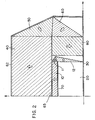
- the optimum design for a 0.4 Tesla field consists of a two layer design where the internal layer 10, 11, 12 is a Nd.Fe.B alloy, designed in accordance with the disclosure of U.S.
- Patent 5,162,771 and the external layer 40, 50, 60 is of ferrite having a lower remanence than that of the inner layer, in accordance with PCT patent application WO-94/02951.
- the outer layer includes a ferrite element 40 generally parallel to the element 10, a triangular section 50 abutting the ends of the section 40, and a further triangular section 60 extending between the section 50 and the mirror 30.
- both the inner layer and the outer layer are hybrid structures, each designed to generate a 0,2 Tesla field within the rectangular cavity.
- the external heavy line 62 denotes a yoke whose function is to close the flux generated by the ferrite layer only.
- Fig. 2 also illustrates a partial yoke 65 that separates the Nd.Fe.B layer from the ferrite structure and a high permeability plate 70 at the interface between the Nd.Fe.B structure and the cavity.
- the plate 70 is designed to filter out the spatial high frequency components of the magnetization tolerances. Other filter components and shimming elements are not shown.
- Fig. 2 illustrates the provision of shunt 80 of magnetic material, for example of ferrite, extending between the yoke 65 and the mirror element 30.
- This shunt as disclosed in PCT patent application WO-94/02951, enables further reductions in the required amount of high strength magnetic material in the magnetic structure.
- Two essential features of the arrangement of Fig. 2 are:
- the magnet structure in accordance with the invention has the following advantages:
Landscapes
- Physics & Mathematics (AREA)
- Condensed Matter Physics & Semiconductors (AREA)
- General Physics & Mathematics (AREA)
- Electromagnetism (AREA)
- Engineering & Computer Science (AREA)
- Power Engineering (AREA)
- Magnetic Resonance Imaging Apparatus (AREA)
- Road Signs Or Road Markings (AREA)
- Aerials With Secondary Devices (AREA)
- Control Of High-Frequency Heating Circuits (AREA)
- Superconductors And Manufacturing Methods Therefor (AREA)
- Building Environments (AREA)
- Shielding Devices Or Components To Electric Or Magnetic Fields (AREA)
- Casings For Electric Apparatus (AREA)
- Magnetic Heads (AREA)
- Mirrors, Picture Frames, Photograph Stands, And Related Fastening Devices (AREA)
Claims (6)
- Construction magnétique ayant une cavité (20) de section rectangulaire dans laquelle est disposé un champ magnétique uniforme, comprenant un élément d'un matériau (30) de perméabilité élevée, ayant une surface plate et disposé afin qu'il délimite une première paroi de la cavité (20), et une structure magnétique (10-14) formée au moins partiellement d'un matériau magnétique permanent délimitant trois parois supplémentaires de la cavité (20), la structure magnétique (10-14) comprenant un premier organe magnétique (10) de section rectangulaire ayant une surface distante de la surface plate de l'élément du matériau (30) de perméabilité élevée, la surface plate et la surface de la structure du matériau magnétique (10) délimitant des parois opposées de la cavité (20),
caractérisée en ce que
la structure magnétique (10-14) comporte en outre plusieurs seconds organes magnétiques (11-14) sous forme de prismes triangulaires ayant des surfaces plates qui s'étendent entre les extrémités opposées du premier organe (10) et la surface plate. - Construction magnétique selon la revendication 1, comprenant en outre une culasse partielle (65) disposée sur la structure magnétique (10-14) et placée à distance de la surface plate, et un shunt magnétique (80) formé d'un matériau dont la rémanence est inférieure à celle de la structure magnétique (10-14) et s'étendant entre la culasse (65) et la surface plate.
- Construction magnétique selon la revendication 1 ou 2, dans laquelle ladite surface de la structure magnétique (10-14) est plate et parallèle à la surface plate.
- Construction magnétique selon l'une quelconque des revendications 1 à 3, comprenant en outre une couche (40, 50, 60) d'un matériau magnétique entourant la structure magnétique (10-14) sur ses côtés placés à l'extérieur de la cavité (20), la couche (40, 50, 60) étant formée d'un matériau magnétique de rémanence inférieure à celle de la structure magnétique (10-14).
- Construction magnétique selon la revendication 4, comprenant en outre une culasse (62) placée sur ladite couche (40, 50, 60) du matériau magnétique.
- Construction magnétique selon la revendication 4 ou 5, dans laquelle ladite couche (40, 50, 60) du matériau magnétique s'étend vers la surface plate.
Priority Applications (2)
| Application Number | Priority Date | Filing Date | Title |
|---|---|---|---|
| AT97203525T ATE229690T1 (de) | 1992-09-01 | 1993-08-18 | Magnetstruktur mit partiellen joch und magnetischem nebenschluss |
| EP97203525A EP0828263B1 (fr) | 1992-09-01 | 1993-08-18 | Structure magnétique contenant une culasse partielle et une dérivation magnétique |
Applications Claiming Priority (3)
| Application Number | Priority Date | Filing Date | Title |
|---|---|---|---|
| US938849 | 1992-09-01 | ||
| US07/938,849 US5278534A (en) | 1992-09-01 | 1992-09-01 | Magnetic structure having a mirror |
| PCT/US1993/007790 WO1994006132A1 (fr) | 1992-09-01 | 1993-08-18 | Structure magnetique a miroir |
Related Child Applications (1)
| Application Number | Title | Priority Date | Filing Date |
|---|---|---|---|
| EP97203525A Division EP0828263B1 (fr) | 1992-09-01 | 1993-08-18 | Structure magnétique contenant une culasse partielle et une dérivation magnétique |
Publications (3)
| Publication Number | Publication Date |
|---|---|
| EP0610493A1 EP0610493A1 (fr) | 1994-08-17 |
| EP0610493A4 EP0610493A4 (fr) | 1995-02-15 |
| EP0610493B1 true EP0610493B1 (fr) | 1998-12-02 |
Family
ID=25472064
Family Applications (2)
| Application Number | Title | Priority Date | Filing Date |
|---|---|---|---|
| EP97203525A Expired - Lifetime EP0828263B1 (fr) | 1992-09-01 | 1993-08-18 | Structure magnétique contenant une culasse partielle et une dérivation magnétique |
| EP93920189A Expired - Lifetime EP0610493B1 (fr) | 1992-09-01 | 1993-08-18 | Structure magnetique a miroir |
Family Applications Before (1)
| Application Number | Title | Priority Date | Filing Date |
|---|---|---|---|
| EP97203525A Expired - Lifetime EP0828263B1 (fr) | 1992-09-01 | 1993-08-18 | Structure magnétique contenant une culasse partielle et une dérivation magnétique |
Country Status (8)
| Country | Link |
|---|---|
| US (1) | US5278534A (fr) |
| EP (2) | EP0828263B1 (fr) |
| AT (2) | ATE229690T1 (fr) |
| AU (1) | AU5080493A (fr) |
| CA (1) | CA2127258A1 (fr) |
| DE (2) | DE69332568T2 (fr) |
| ES (2) | ES2124323T3 (fr) |
| WO (1) | WO1994006132A1 (fr) |
Families Citing this family (8)
| Publication number | Priority date | Publication date | Assignee | Title |
|---|---|---|---|---|
| US5382936A (en) * | 1992-06-02 | 1995-01-17 | The United States Of America As Represented By The Secretary Of The Army | Field augmented permanent magnet structures |
| CA2141188A1 (fr) * | 1992-07-27 | 1994-02-03 | New York University | Aimants a forte puissance pour applications medicales |
| EP0616230B1 (fr) * | 1993-03-15 | 1998-08-05 | Siemens Aktiengesellschaft | Aimant pour champ homogène avec un arrangement de disques polaires séparés par des espaces d'air de correction pour chaque pièce polaire |
| FI933834A7 (fi) * | 1993-09-01 | 1995-03-02 | Picker Nordstar Oy | Magneettikuvauslaitteen napakenkä |
| US5798680A (en) * | 1994-04-15 | 1998-08-25 | New York University | Strapped open magnetic structure |
| US6225887B1 (en) | 1996-11-22 | 2001-05-01 | New York University | Generation of highly uniform magnetic fields with magnetized wedges |
| AU2944900A (en) * | 1999-08-03 | 2001-02-19 | Seong Ho Bae | Space defining structure for magnetic homogenization |
| RU2603348C2 (ru) * | 2015-03-26 | 2016-11-27 | Закрытое акционерное общество "Научно - техническое объединение ПРИБОРСЕРВИС" (ЗАО "НТО ПРИБОРСЕРВИС") | Магниторазрядный насос |
Citations (1)
| Publication number | Priority date | Publication date | Assignee | Title |
|---|---|---|---|---|
| WO1992022076A1 (fr) * | 1991-05-30 | 1992-12-10 | New York University | Aimant permanent a haute efficacite en forme d'etrier |
Family Cites Families (11)
| Publication number | Priority date | Publication date | Assignee | Title |
|---|---|---|---|---|
| US2832932A (en) * | 1951-08-07 | 1958-04-29 | Baermann Max | Magnet arrangement for the production of eddy currents |
| US3227931A (en) * | 1963-07-18 | 1966-01-04 | Zenith Radio Corp | Permanent-magnet uniform-field-producing apparatus |
| US3768054A (en) * | 1972-04-03 | 1973-10-23 | Gen Electric | Low flux leakage magnet construction |
| US4456898A (en) * | 1982-02-11 | 1984-06-26 | General Electric Company | Thermal compensators for magnetic circuits |
| JPS6088408A (ja) * | 1983-10-19 | 1985-05-18 | Sumitomo Special Metals Co Ltd | 磁界発生装置 |
| FR2611975B1 (fr) * | 1987-03-03 | 1995-02-17 | Commissariat Energie Atomique | Systeme d'aimants permanents pour un champ magnetique intense |
| US4861752A (en) * | 1988-05-27 | 1989-08-29 | The United States Of America As Represented By The Secretary Of The Army | High-field permanent-magnet structures |
| US4835506A (en) * | 1988-05-27 | 1989-05-30 | The United States Of America As Represented By The Secretary Of The Army | Hollow substantially hemispherical permanent magnet high-field flux source |
| US4859976A (en) * | 1989-03-17 | 1989-08-22 | The United States Of America As Represented By The Secretary Of The Army | Periodic permanent magnet structures |
| US4998083A (en) * | 1989-11-02 | 1991-03-05 | New York University | Yokeless permanent magnet structure and method of construction |
| US5107239A (en) * | 1991-05-30 | 1992-04-21 | New York University | Hybrid permanent magnets |
-
1992
- 1992-09-01 US US07/938,849 patent/US5278534A/en not_active Expired - Lifetime
-
1993
- 1993-08-18 WO PCT/US1993/007790 patent/WO1994006132A1/fr not_active Ceased
- 1993-08-18 CA CA002127258A patent/CA2127258A1/fr not_active Abandoned
- 1993-08-18 DE DE69332568T patent/DE69332568T2/de not_active Expired - Lifetime
- 1993-08-18 AT AT97203525T patent/ATE229690T1/de not_active IP Right Cessation
- 1993-08-18 ES ES93920189T patent/ES2124323T3/es not_active Expired - Lifetime
- 1993-08-18 ES ES97203525T patent/ES2187721T3/es not_active Expired - Lifetime
- 1993-08-18 EP EP97203525A patent/EP0828263B1/fr not_active Expired - Lifetime
- 1993-08-18 AU AU50804/93A patent/AU5080493A/en not_active Abandoned
- 1993-08-18 AT AT93920189T patent/ATE174128T1/de not_active IP Right Cessation
- 1993-08-18 DE DE69322369T patent/DE69322369T2/de not_active Expired - Lifetime
- 1993-08-18 EP EP93920189A patent/EP0610493B1/fr not_active Expired - Lifetime
Patent Citations (1)
| Publication number | Priority date | Publication date | Assignee | Title |
|---|---|---|---|---|
| WO1992022076A1 (fr) * | 1991-05-30 | 1992-12-10 | New York University | Aimant permanent a haute efficacite en forme d'etrier |
Also Published As
| Publication number | Publication date |
|---|---|
| EP0828263A1 (fr) | 1998-03-11 |
| DE69322369D1 (de) | 1999-01-14 |
| ATE174128T1 (de) | 1998-12-15 |
| DE69332568D1 (de) | 2003-01-23 |
| EP0610493A4 (fr) | 1995-02-15 |
| DE69332568T2 (de) | 2003-07-10 |
| AU5080493A (en) | 1994-03-29 |
| CA2127258A1 (fr) | 1994-03-02 |
| ATE229690T1 (de) | 2002-12-15 |
| DE69322369T2 (de) | 1999-06-17 |
| US5278534A (en) | 1994-01-11 |
| EP0610493A1 (fr) | 1994-08-17 |
| ES2124323T3 (es) | 1999-02-01 |
| WO1994006132A1 (fr) | 1994-03-17 |
| EP0828263B1 (fr) | 2002-12-11 |
| ES2187721T3 (es) | 2003-06-16 |
Similar Documents
| Publication | Publication Date | Title |
|---|---|---|
| US5250901A (en) | Open architecture iron core electromagnet for MRI using superconductive winding | |
| US5495222A (en) | Open permanent magnet structure for generating highly uniform field | |
| EP0985934B1 (fr) | Circuit magnétique avec aimants permanents montés en opposition | |
| US5519372A (en) | Magnets providing patient accessibility | |
| WO1997007730A3 (fr) | Sonde irm pour imagerie externe | |
| EP0231879A3 (fr) | Bobines blindées de gradient pour la formation d'images de résonance magnétique nucléaire | |
| EP0610493B1 (fr) | Structure magnetique a miroir | |
| US5798680A (en) | Strapped open magnetic structure | |
| US5412365A (en) | High field magnets for medical applications | |
| US5614880A (en) | Superconducting magnet with symmetrical plural air gaps | |
| US7199689B1 (en) | High field NMR permanent magnetic structure | |
| US6211676B1 (en) | MRI magnets | |
| JPH07375A (ja) | 一定の空間内で安定かつ均等な磁気誘導を生成するための永久磁石構造 | |
| US5825187A (en) | Magnetic circuit system with opposite permanent magnets | |
| US6504461B2 (en) | Open magnet with recessed field shaping coils | |
| US7116198B1 (en) | MRI conical magnet imaging system | |
| WO1999056293A2 (fr) | Structure magnetique unipolaire ouverte | |
| JPS625161A (ja) | Mri用マグネツト | |
| EP1300688B1 (fr) | Un aimant supraconducteur, en particulier pour appareil d'imagerie RM | |
| Abele | Generation of highly uniform fields with permanent magnets | |
| Kakugawa et al. | Shielding stray magnetic fields of open high field MRI magnets | |
| JPH02184003A (ja) | Mri用磁界発生装置 | |
| JPH0314012Y2 (fr) | ||
| JPH03203203A (ja) | Mri用磁界発生装置 | |
| JPH07265280A (ja) | Mri用磁界発生装置 |
Legal Events
| Date | Code | Title | Description |
|---|---|---|---|
| PUAI | Public reference made under article 153(3) epc to a published international application that has entered the european phase |
Free format text: ORIGINAL CODE: 0009012 |
|
| 17P | Request for examination filed |
Effective date: 19940526 |
|
| AK | Designated contracting states |
Kind code of ref document: A1 Designated state(s): AT BE CH DE DK ES FR GB GR IE IT LI LU MC NL PT SE |
|
| A4 | Supplementary search report drawn up and despatched |
Effective date: 19941230 |
|
| AK | Designated contracting states |
Kind code of ref document: A4 Designated state(s): AT BE CH DE DK ES FR GB GR IE IT LI LU MC NL PT SE |
|
| 17Q | First examination report despatched |
Effective date: 19960612 |
|
| GRAG | Despatch of communication of intention to grant |
Free format text: ORIGINAL CODE: EPIDOS AGRA |
|
| GRAG | Despatch of communication of intention to grant |
Free format text: ORIGINAL CODE: EPIDOS AGRA |
|
| GRAG | Despatch of communication of intention to grant |
Free format text: ORIGINAL CODE: EPIDOS AGRA |
|
| GRAH | Despatch of communication of intention to grant a patent |
Free format text: ORIGINAL CODE: EPIDOS IGRA |
|
| GRAH | Despatch of communication of intention to grant a patent |
Free format text: ORIGINAL CODE: EPIDOS IGRA |
|
| ITF | It: translation for a ep patent filed | ||
| GRAA | (expected) grant |
Free format text: ORIGINAL CODE: 0009210 |
|
| AK | Designated contracting states |
Kind code of ref document: B1 Designated state(s): AT BE CH DE DK ES FR GB GR IE IT LI LU MC NL PT SE |
|
| PG25 | Lapsed in a contracting state [announced via postgrant information from national office to epo] |
Ref country code: NL Free format text: LAPSE BECAUSE OF FAILURE TO SUBMIT A TRANSLATION OF THE DESCRIPTION OR TO PAY THE FEE WITHIN THE PRESCRIBED TIME-LIMIT Effective date: 19981202 Ref country code: LI Free format text: LAPSE BECAUSE OF FAILURE TO SUBMIT A TRANSLATION OF THE DESCRIPTION OR TO PAY THE FEE WITHIN THE PRESCRIBED TIME-LIMIT Effective date: 19981202 Ref country code: GR Free format text: LAPSE BECAUSE OF NON-PAYMENT OF DUE FEES Effective date: 19981202 Ref country code: CH Free format text: LAPSE BECAUSE OF FAILURE TO SUBMIT A TRANSLATION OF THE DESCRIPTION OR TO PAY THE FEE WITHIN THE PRESCRIBED TIME-LIMIT Effective date: 19981202 Ref country code: BE Free format text: LAPSE BECAUSE OF FAILURE TO SUBMIT A TRANSLATION OF THE DESCRIPTION OR TO PAY THE FEE WITHIN THE PRESCRIBED TIME-LIMIT Effective date: 19981202 Ref country code: AT Free format text: LAPSE BECAUSE OF FAILURE TO SUBMIT A TRANSLATION OF THE DESCRIPTION OR TO PAY THE FEE WITHIN THE PRESCRIBED TIME-LIMIT Effective date: 19981202 |
|
| REF | Corresponds to: |
Ref document number: 174128 Country of ref document: AT Date of ref document: 19981215 Kind code of ref document: T |
|
| REG | Reference to a national code |
Ref country code: CH Ref legal event code: EP |
|
| REF | Corresponds to: |
Ref document number: 69322369 Country of ref document: DE Date of ref document: 19990114 |
|
| REG | Reference to a national code |
Ref country code: IE Ref legal event code: FG4D |
|
| REG | Reference to a national code |
Ref country code: ES Ref legal event code: FG2A Ref document number: 2124323 Country of ref document: ES Kind code of ref document: T3 |
|
| PG25 | Lapsed in a contracting state [announced via postgrant information from national office to epo] |
Ref country code: SE Free format text: LAPSE BECAUSE OF FAILURE TO SUBMIT A TRANSLATION OF THE DESCRIPTION OR TO PAY THE FEE WITHIN THE PRESCRIBED TIME-LIMIT Effective date: 19990302 Ref country code: PT Free format text: LAPSE BECAUSE OF FAILURE TO SUBMIT A TRANSLATION OF THE DESCRIPTION OR TO PAY THE FEE WITHIN THE PRESCRIBED TIME-LIMIT Effective date: 19990302 Ref country code: DK Free format text: LAPSE BECAUSE OF FAILURE TO SUBMIT A TRANSLATION OF THE DESCRIPTION OR TO PAY THE FEE WITHIN THE PRESCRIBED TIME-LIMIT Effective date: 19990302 |
|
| ET | Fr: translation filed | ||
| NLV1 | Nl: lapsed or annulled due to failure to fulfill the requirements of art. 29p and 29m of the patents act | ||
| REG | Reference to a national code |
Ref country code: CH Ref legal event code: PL |
|
| PG25 | Lapsed in a contracting state [announced via postgrant information from national office to epo] |
Ref country code: LU Free format text: LAPSE BECAUSE OF NON-PAYMENT OF DUE FEES Effective date: 19990818 Ref country code: IE Free format text: LAPSE BECAUSE OF NON-PAYMENT OF DUE FEES Effective date: 19990818 |
|
| PLBE | No opposition filed within time limit |
Free format text: ORIGINAL CODE: 0009261 |
|
| STAA | Information on the status of an ep patent application or granted ep patent |
Free format text: STATUS: NO OPPOSITION FILED WITHIN TIME LIMIT |
|
| 26N | No opposition filed | ||
| PG25 | Lapsed in a contracting state [announced via postgrant information from national office to epo] |
Ref country code: MC Free format text: LAPSE BECAUSE OF NON-PAYMENT OF DUE FEES Effective date: 20000229 |
|
| REG | Reference to a national code |
Ref country code: IE Ref legal event code: MM4A |
|
| REG | Reference to a national code |
Ref country code: GB Ref legal event code: IF02 |
|
| PGFP | Annual fee paid to national office [announced via postgrant information from national office to epo] |
Ref country code: ES Payment date: 20100915 Year of fee payment: 18 |
|
| PGFP | Annual fee paid to national office [announced via postgrant information from national office to epo] |
Ref country code: FR Payment date: 20100824 Year of fee payment: 18 Ref country code: DE Payment date: 20100812 Year of fee payment: 18 |
|
| PGFP | Annual fee paid to national office [announced via postgrant information from national office to epo] |
Ref country code: GB Payment date: 20100818 Year of fee payment: 18 |
|
| PGFP | Annual fee paid to national office [announced via postgrant information from national office to epo] |
Ref country code: IT Payment date: 20110812 Year of fee payment: 19 |
|
| GBPC | Gb: european patent ceased through non-payment of renewal fee |
Effective date: 20110818 |
|
| REG | Reference to a national code |
Ref country code: FR Ref legal event code: ST Effective date: 20120430 |
|
| REG | Reference to a national code |
Ref country code: DE Ref legal event code: R119 Ref document number: 69322369 Country of ref document: DE Effective date: 20120301 |
|
| PG25 | Lapsed in a contracting state [announced via postgrant information from national office to epo] |
Ref country code: GB Free format text: LAPSE BECAUSE OF NON-PAYMENT OF DUE FEES Effective date: 20110818 Ref country code: FR Free format text: LAPSE BECAUSE OF NON-PAYMENT OF DUE FEES Effective date: 20110831 |
|
| PG25 | Lapsed in a contracting state [announced via postgrant information from national office to epo] |
Ref country code: IT Free format text: LAPSE BECAUSE OF NON-PAYMENT OF DUE FEES Effective date: 20120818 |
|
| REG | Reference to a national code |
Ref country code: ES Ref legal event code: FD2A Effective date: 20130531 |
|
| PG25 | Lapsed in a contracting state [announced via postgrant information from national office to epo] |
Ref country code: DE Free format text: LAPSE BECAUSE OF NON-PAYMENT OF DUE FEES Effective date: 20120301 |
|
| PG25 | Lapsed in a contracting state [announced via postgrant information from national office to epo] |
Ref country code: ES Free format text: LAPSE BECAUSE OF NON-PAYMENT OF DUE FEES Effective date: 20110819 |