EP0610841A2 - Kabelschneider für Schnitte längs der Mantellinie und der Umfangslinie - Google Patents
Kabelschneider für Schnitte längs der Mantellinie und der Umfangslinie Download PDFInfo
- Publication number
- EP0610841A2 EP0610841A2 EP94101792A EP94101792A EP0610841A2 EP 0610841 A2 EP0610841 A2 EP 0610841A2 EP 94101792 A EP94101792 A EP 94101792A EP 94101792 A EP94101792 A EP 94101792A EP 0610841 A2 EP0610841 A2 EP 0610841A2
- Authority
- EP
- European Patent Office
- Prior art keywords
- knife holder
- cable
- knife
- drive lever
- along
- Prior art date
- Legal status (The legal status is an assumption and is not a legal conclusion. Google has not performed a legal analysis and makes no representation as to the accuracy of the status listed.)
- Granted
Links
Images
Classifications
-
- H—ELECTRICITY
- H02—GENERATION; CONVERSION OR DISTRIBUTION OF ELECTRIC POWER
- H02G—INSTALLATION OF ELECTRIC CABLES OR LINES, OR OF COMBINED OPTICAL AND ELECTRIC CABLES OR LINES
- H02G1/00—Methods or apparatus specially adapted for installing, maintaining, repairing or dismantling electric cables or lines
- H02G1/12—Methods or apparatus specially adapted for installing, maintaining, repairing or dismantling electric cables or lines for removing insulation or armouring from cables, e.g. from the end thereof
- H02G1/1202—Methods or apparatus specially adapted for installing, maintaining, repairing or dismantling electric cables or lines for removing insulation or armouring from cables, e.g. from the end thereof by cutting and withdrawing insulation
- H02G1/1204—Hand-held tools
- H02G1/1229—Hand-held tools the cutting element making a longitudinal, and a transverse or a helical cut
Definitions
- this flattening when the tool is placed through the cable sheathing, as a result, during the execution of the cut, this flattening lies between the cable core and the sheathing and acts during the advancement of the cutting edge by actuating the hand lever in the manner of a can opener Guide.
- These known cutting tools also have devices for adjusting the bearing axis of the drive lever in relation to the contact surface of the knife carrier and / or adjusting devices for adjusting the depth of penetration of the knife and for easier determination of the cutting length.
- Interchangeable parts that can be plugged onto the knife carrier also allow the knife length to be adapted to the thickness of the cable sheathing. All of these known tools are unsuitable for making frequently required cuts along the circumferential line of the cable sheathing and only allow cuts along the sheath line, the knife projection being adapted to the thickness of the sheath.
- the invention has for its object to provide a tool described in the introduction, which besides the execution of cuts along the surface line of Cable sheathing, including those along the circumference and without the use of additional aids.
- the invention proposes a connection via a hinge part, e.g. over tabs or through, slidably arranged in guides, providing an adaptation of the drive geometry between the knife carrier and the drive lever to the outer curve of the cable sheathing is achieved.
- the shape of the contact surfaces for the two cutting directions will have a single common point, at this common point the cutting edge of the knife is positioned and here, at an angle of approximately 90 °, the contact lines intersect for the execution of the cut along the surface line with the one for the execution along the circumferential line of the cable sheathing.
- the guidance of the knife holder during the execution of both cutting directions can be formed by two mutually perpendicular grooves, which correspond approximately to the outer curve of the cable sheath, or it can be formed by four projections, which by grinding the cable sheath to be cut, the guidance in both cutting directions take over.
- the position of these projections can be adjusted symmetrically with respect to the deposit lines in order to thereby adapt the support geometry to the outer curve of the cable sheathing.
- a part can be provided as a support, which can be rotated or inserted in different positions according to an axis which runs essentially through the cutting edge of the knife and which has a single guide groove, two perpendicular to one another has running guide grooves of different shape or guide projections.
- the articulation of the tabs on the knife holder is not completely free-wheeling but requires a certain force overcoming in order to achieve a change in position, if necessary this can also be done in jerks to prevent a change in the angle between the knife holder and connecting tabs during actuation of the drive lever.
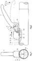
- FIG. 1 shows a view of the cable cutter from the rear during the execution of a cut along the surface line.
- FIG. 2 shows a side view of the cable jacket cutter according to the invention during the execution of a cut along the jacket line, the cable being partially shown in longitudinal section.
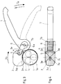
- FIG 3 shows a side view of the cable jacket cutter according to the invention during the execution of a cut along the circumferential line, the cable being shown in cross section.
- Figure 4 is a bottom view of the cable jacket cutter shown in Figure 3 to show the support area of the knife holder.
- the cable 1 is covered by a sheath 1a, which is to be cut in the longitudinal direction 3a (FIGS. 1, 2) and / or along a circumferential line 3b (FIGS. 3, 4).
- the knife 2 is with the cutting edge in the area of the intersection between the support lines 3d, which extend at an angle of 90 ° to one another, 3c, which correspond to the two possible cutting directions, is provided on the knife holder 3.
- the shape of the support area of the knife holder is determined by two grooves running at right angles to one another, which form four projections 3e, which are each arranged symmetrically with respect to the support lines 3d, 3c.
- two tabs 4 are pivotally articulated 6a 5, at the opposite ends of which a drive lever 7 with curved toothing 7b is articulated 6.
- the pivoting movement of the tabs 4 around the hinge pin 5 on the knife holder 3 is advantageously not completely free, but takes place by overcoming a certain friction or in jerks.
Landscapes
- Removal Of Insulation Or Armoring From Wires Or Cables (AREA)
- Electric Cable Installation (AREA)
- Insulated Conductors (AREA)
- Communication Cables (AREA)
- Scissors And Nippers (AREA)
Abstract
Description
- Es sind handbetätigte Kabelschneider für die Ausführung von Schnitten längs der Mantellinie von Ummantelungen elektrischer Kabel aus den Beschreibungen der DE 24 02 377, DE 30 09 888 und EP 0 338 273 bekannt; all diese Werkzeuge bestehen aus einem Messerträger an welchem ein mit Zahnsektor versehener Antriebshebel schwenkbar gelagert ist. Das Messer, welches am Messerträger gegebenenfalls einstellbar oder/und rückziehbar befestigt ist, weist an der Schneidenspitze eine Abflachung auf, welche quer zur Schneide verläuft. Mittels dieser Abflachung wird beim Ansetzen des Werkzeuges durch die Kabelummantelung eingestochen, in der Folge, während der Ausführung des Schnittes, liegt diese Abflachung zwischen Kabelseele und Ummantelung und wirkt dabei, während der Vorrückung der Schneide, durch Betätigung des Handhebels nach Art eines Dosenöffners, als Führung. Diese bekannten Schneidwerkzeuge verfügen überdies über Einrichtungen zur Verstellung der Lagerachse des Antriebshebels in Bezug auf die Auflagefläche des Messerträgers und/oder über Einstellvorrichtungen für die Anpassung der Eindringtiefe des Messers sowie für die leichtere Bestimmung der Schnittlänge. Auf den Messerträger aufsteckbare, austauschbare Teile ermöglichen überdies eine Anpassung der Messerlänge an die Stärke der Kabelummantelung. Alle diese bekannten Werkzeuge sind für die Ausführung von öfters erforderlichen Schnitten längs der Umfangslinie der Kabelummantelung, ungeeignet und ermöglichen ausschließlich Schnitte längs der Mantellinie wobei eine Anpassung des Messervorsprungs an die Stärke der Ummantelung vorgesehen ist.
- Die Erfindung stellt sich die Aufgabe ein eingangs beschriebenes Werkzeug zu schaffen, welches außer die Ausführung von Schnitten längs der Mantellinie von Kabelummantelungen, auch solche längs der Umfangslinie und ohne den Einsatz weiterer Hilfsmittel, ermöglicht.
- Zur Lösung dieser Aufgabe schlägt die Erfindung vor zwischen dem Messerträger und dem Antriebshebel eine Verbindung über ein Gelenkteil, z.B. über Laschen oder durch, in Führungen verschiebbar angeordnete Lagerung, vorzusehen, wobei eine Anpassung der Antriebsgeometrie zwischen Messerträger und Antriebshebel an die Außenrundung der Kabelummantelung erreicht wird.
- Der Einsatz des selben Werkzeugs für zwei unterschiedliche Schnittrichtungen an Oberflächen mit unterschiedlichem Formverlauf, erfordert eine entsprechende unterschiedliche Formgebung am Auflagebereich des Messerhalters. Insbesondere wird die Form der Auflageflächen für die beiden Schnittrichtungen einen einzigen gemeinsamen Punkt aufweisen, an diesem gemeinsamen Punkt ist die Schneide des Messers positioniert und hier kreuzen sich, in einem Winkel von ca.90°, die Auflagelinien für die Ausführung des Schnittes längs der Mantellinie mit Jener für die Ausführung längs der Umfangslinie der Kabelummantelung. Die Führung des Messerhalters während der Ausführung beider Schnittrichtungen kann durch zwei, zueinander rechtwinklig verlaufender Rillen gebildet sein, welche ungefähr der Außenrundung der Kabelummantelung entsprechen, oder sie kann durch vier Vorsprünge gebildet werden, welche durch Schleifen an der aufzuschneidenden Kabelummantelung, die Führung bei beiden Schnittrichtungen übernehmen.
- Erfindungsgemäß kann die Position dieser Vorsprünge symmetrisch in Bezug auf die Aflagelinien verstellbar sein um dadurch die Auflagegeometrie der Außenrundung der Kabelummantelung anzupassen.
- Gemäß einer Weiterentwicklung des Erfindungsgedankens kann als Auflage ein, nach einer Achse welche wesentlich durch die Schneide des Messers läuft, drehbares oder in verschiedenen Positionen einsteckbares Teil, vorgesehen sein, welches eine einzige Führungsrille, zwei senkrecht zueinander verlaufende Führungsrillen unterschiedlicher Form oder Führungsvorsprünge aufweist.
- Vorteilhafterweise ist die Anlenkung der Laschen am Messerhalter nicht vollständig freiläufig sondern erfordert eine bestimmte Kraftüberwindung um eine Lageveränderung zu erreichen, gegebenenfalls kann diese auch ruckweise erfolgen um zu verhindern, daß während der Betätigung des Antriebhebels eine Veränderung des Winkels zwischen Messerhalter und Verbindungslaschen stattfindet.
- Die Erfindung wird anschließend anhand eines, in den beiliegenden Zeichnungen schematisch dargestellten, vorzuziehenden Ausführungsbeispieles eines erfindungsgemäßen Kabelmantelschneiders, näher erklärt; dbei erfüllen die Zeichnungen rein erklärenden, nicht begrenzenden Zweck.
- Die Fig.1 zeigt eine Ansicht des Kabelschneiders von hinten während der Ausführung eines Schnittes längs der Mantellinie.
- Die Fig.2 zeigt eine Seitenansicht des erfindungsgemäßen Kabelmantelschneiders während der Ausführung eines Schnittes längs der Mantellinie, wobei der Kabel teilweise im Längsschnitt dargestellt ist.
- Die Fig.3 zeigt eine Seitenansicht des erfindungsgemäßen Kabelmantelschneiders während der Ausführung eines Schnittes längs der Umfangslinie, wobei der Kabel im Querschnitt dargestellt ist.
- Die Fig.4 ist eine Ansicht von unten, des in Fig.3 dargestellten Kabelmantelschneiders, um den Auflagebereich des Messerhalters zu zeigen.
- Der Kabel 1 ist von einer Ummantelung 1a umhüllt, welche in Längsrichtung 3a (Figg.1, 2) oder/und entlang einer Umfangslinie 3b (Figg.3, 4) zu durchtrennen ist. Das Messer 2 ist mit der Schneide im Bereich des Schnittpunktes zwischen den, zueinander in einem Winkel von 90° verlaufenden, Auflagelinien 3d, 3c, welche den zwei möglichen Schnittrichtungen entsprechen, am Messerhalter 3 vorgesehen. Die Form des Auflagebereiches des Messerhalters wird durch zwei, zueinander rechtwinklig verlaufender Rillen bestimmt, welche vier Vorsprünge 3e bilden, die jeweils zu den Auflagelinien 3d, 3c symmetrisch angeordnet sind. Im vorderen Bereich des Messerhalters, bezogen auf die Schnittrichtung, sind zwei Laschen 4 schwenkbar 6a angelenkt 5, an deren entgegengesetzten Enden ein Antriebshebel 7 mit bogenförmiger Verzahnung 7b angelenkt 6 ist. Die Schwenkbewegung der Laschen 4 um den Gelenkzapfen 5 am Messerhalter 3 ist vorteilhafterweise nicht vollständig frei sondern erfolgt durch Überwindung einer bestimmten Reibung oder ruckweise.
Claims (6)
- Kabelmantelschneider bestehend aus einem Messerhalter der durch Betätigen eines, mit bogenförmiger Verzahnung versehenen, Antriebhebels bewegt wird, dadurch gekennzeichnet, daß die Anlenkung (6) des Antriebhebels (7) schwenkbar (6a), in Bezug auf den Messerhalter (3), innerhalb einer Ebene erfolgt, welche die Schneide des Messers (2) und die Schnittrichtung (3a, 3b) beinhaltet.
- Kabelmantelschneider nach Anspruch 1, dadurch gekennzeichnet, daß die Anlenkung (6) des Antriebhebels (7) um einen Zapfen (5) schwenkbar ist, welcher, bezogen auf die Schnittrichtung, im vorderen Bereich des Messerhalters (3) vorgesehen ist und daß die Verbindung zwischen der Anlenkung (5) am Messerhalter (3) und der Lagerung (6) des Antriebhebels (7) über mindestens eine Lasche (4) erfolgt.
- Kabelschneider nach Anspruch 1 und teilweise nach Anspruch 2, dadurch gekennzeichnet, daß die Beweglichkeit (6a) der Lagerung (6) des Antriebhebels (7) bezüglich dem Messerhalter (3) mittels, vom Messerhalter abstehender, mit Führungsrillen versehenen, Seitenteile, an welchen der Lagerzapfen (6) für den Antriebshebel (7) verschiebbar eingreift, erreicht wird und daß diese Seitenteile feststehend mit dem Messerhalter verbunden sind oder schwenkbar an diesem angelenkt sind und/oder einstellbar sind.
- Kabelschneider nach den Ansprüchen von 1 bis 3, dadurch gekennzeichnet, daß der Auflagebereich am Messerhalter (3) wesentlich durch den Verlauf zweier Auflagelinien (3d, 3c) bestimmt wird, welche den beiden Schnittrichtungen längs der Mantellinie (3a) und längs der Umfangslinie (3b) entsprechen und sich in einem Winkel von 90° schneiden und daß die Schneide des Messers im Bereich dieses Schnittpunktes angeordnet ist.
- Kabelmantelschneider nach den Ansprüchen von 1 bis 4, dadurch gekennzeichnet, daß die Führung des Messerhalters (3) an der Außenform des Kabels (1) während der Schnittrichtung, sei es entlang der Mantellinie (3a), als auch entlang der Umfangslinie (3b) durch zwei zueinander rechtwinklig verlaufender Rillen, oder durch vier, bezüglich der Auflagelinien (3d, 3c) symmetrisch angeordnete, Vorsprünge (3e), erfolgt.
- Kabelmantelschneider nach den Ansprüchen von 1 bis 5, dadurch gekennzeichnet, daß die Auflage für den Messerhalter (3) durch ein drehbares oder in verschiedenen Positionen aufsteckbares Element gebildet wird, wobei die Drehachse längs der Schneide des Messers (2) oder parallel dazu verläuft und daß die Auflageform von mindestens einer Rille, von mehr als zwei Rillen unterschiedlicher oder gleicher Form oder von Führungsvorsprüngen, bestimmt wird.
Applications Claiming Priority (2)
| Application Number | Priority Date | Filing Date | Title |
|---|---|---|---|
| ITBZ930006A IT1270514B (it) | 1993-02-08 | 1993-02-08 | Attrezzo per il taglio longitudinale e circonferenziale di guaine di cavi. |
| ITBZ930006 | 1993-02-08 |
Publications (3)
| Publication Number | Publication Date |
|---|---|
| EP0610841A2 true EP0610841A2 (de) | 1994-08-17 |
| EP0610841A3 EP0610841A3 (de) | 1994-08-31 |
| EP0610841B1 EP0610841B1 (de) | 1997-01-02 |
Family
ID=11346581
Family Applications (1)
| Application Number | Title | Priority Date | Filing Date |
|---|---|---|---|
| EP94101792A Expired - Lifetime EP0610841B1 (de) | 1993-02-08 | 1994-02-07 | Kabelmantelschneider für Schnitte längs der Mantellinie und der Umfangslinie |
Country Status (5)
| Country | Link |
|---|---|
| EP (1) | EP0610841B1 (de) |
| AT (1) | ATE147195T1 (de) |
| DE (1) | DE59401434D1 (de) |
| ES (1) | ES2097558T3 (de) |
| IT (1) | IT1270514B (de) |
Cited By (3)
| Publication number | Priority date | Publication date | Assignee | Title |
|---|---|---|---|---|
| EP2234229A1 (de) | 2009-03-26 | 2010-09-29 | Intercable Srl | Abmantelungswerkzeug für Elektrokabel |
| DE102010001872A1 (de) | 2010-02-12 | 2011-08-18 | "Weißer Rabe" soziale Betriebe und Dienste GmbH, 80336 | Kabelschälmaschine zum maschinellen Auftrennen eines Kabelmantels |
| CN113031155A (zh) * | 2021-03-19 | 2021-06-25 | 杭州富通通信技术股份有限公司 | 一种光缆剪线钳 |
Families Citing this family (5)
| Publication number | Priority date | Publication date | Assignee | Title |
|---|---|---|---|---|
| DE102023106643A1 (de) | 2023-03-16 | 2024-09-19 | Knipex-Werk C. Gustav Putsch Kg | Handgerät mit einem Messer |
| DE202024102944U1 (de) | 2024-06-05 | 2024-07-17 | Armex Solutions Gmbh | Vorrichtung zum Aufschneiden von Schutzmantelrohren |
| DE202024102948U1 (de) | 2024-06-05 | 2024-07-17 | Armex Solutions Gmbh | Vorrichtung zum Aufschneiden von Schutzmantelrohren |
| DE102024115603A1 (de) | 2024-06-05 | 2025-12-11 | Armex Solutions Gmbh | Vorrichtung zum Aufschneiden von Schutzmantelrohren |
| DE102024115598A1 (de) | 2024-06-05 | 2025-12-11 | Armex Solutions Gmbh | Vorrichtung zum Aufschneiden von Schutzmantelrohren |
Family Cites Families (2)
| Publication number | Priority date | Publication date | Assignee | Title |
|---|---|---|---|---|
| DE2306031A1 (de) * | 1973-02-07 | 1974-08-15 | Siemens Ag | Schneidwerkzeug zum entfernen von kabelmaenteln |
| DE3710754C1 (en) * | 1987-03-31 | 1988-06-16 | Rose Walter Gmbh & Co Kg | Cable sheath (jacket) cutter |
-
1993
- 1993-02-08 IT ITBZ930006A patent/IT1270514B/it active IP Right Grant
-
1994
- 1994-02-07 DE DE59401434T patent/DE59401434D1/de not_active Expired - Lifetime
- 1994-02-07 ES ES94101792T patent/ES2097558T3/es not_active Expired - Lifetime
- 1994-02-07 EP EP94101792A patent/EP0610841B1/de not_active Expired - Lifetime
- 1994-02-07 AT AT94101792T patent/ATE147195T1/de active
Cited By (4)
| Publication number | Priority date | Publication date | Assignee | Title |
|---|---|---|---|---|
| EP2234229A1 (de) | 2009-03-26 | 2010-09-29 | Intercable Srl | Abmantelungswerkzeug für Elektrokabel |
| DE102010001872A1 (de) | 2010-02-12 | 2011-08-18 | "Weißer Rabe" soziale Betriebe und Dienste GmbH, 80336 | Kabelschälmaschine zum maschinellen Auftrennen eines Kabelmantels |
| DE102010001872B4 (de) * | 2010-02-12 | 2011-09-01 | "Weißer Rabe" soziale Betriebe und Dienste GmbH | Kabelschälmaschine zum maschinellen Auftrennen eines Kabelmantels |
| CN113031155A (zh) * | 2021-03-19 | 2021-06-25 | 杭州富通通信技术股份有限公司 | 一种光缆剪线钳 |
Also Published As
| Publication number | Publication date |
|---|---|
| ITBZ930006A0 (it) | 1993-02-08 |
| ATE147195T1 (de) | 1997-01-15 |
| ES2097558T3 (es) | 1997-04-01 |
| IT1270514B (it) | 1997-05-06 |
| EP0610841B1 (de) | 1997-01-02 |
| DE59401434D1 (de) | 1997-02-13 |
| EP0610841A3 (de) | 1994-08-31 |
| ITBZ930006A1 (it) | 1994-08-08 |
Similar Documents
| Publication | Publication Date | Title |
|---|---|---|
| EP3792009B1 (de) | Handgeführtes arbeitsgerät mit einem werkzeug | |
| EP2264495B1 (de) | Werkzeug zur Verarbeitung von Lichtwellenleitern | |
| DE69831996T2 (de) | Handwerkzeug | |
| DE69422173T2 (de) | Schneidzange, insbesondere Gartenschere | |
| DE2709910C3 (de) | Abisoliervorrichtung | |
| DE29901705U1 (de) | Mehrzweckwerkzeug | |
| DE102018117203B4 (de) | Messer | |
| DE8905574U1 (de) | Antriebseinrichtung für ein motorisch antreibbares Klappverdeck | |
| DE202010005761U1 (de) | Handhabungsvorrichtung für ein zangenartiges Werkzeug | |
| EP0601388A1 (de) | Zangendosenöffner | |
| DE112017001575T5 (de) | Bandabgabewerkzeug | |
| EP0610841A2 (de) | Kabelschneider für Schnitte längs der Mantellinie und der Umfangslinie | |
| DE3030610A1 (de) | Werkzeug zum abisolieren eines isolierten elektrischen leiters | |
| EP1816716B1 (de) | Abmantelwerkzeug | |
| EP0461080A1 (de) | Abisolierzange | |
| EP0222112B1 (de) | Vorrichtung zum Abisolieren von Kabeln | |
| DE102021131694B3 (de) | Kabelentmantelungswerkzeug | |
| DE2932501C2 (de) | Abisoliergerät | |
| DE3842754A1 (de) | Schneidevorrichtung fuer das selektive durchtrennen der mehrlagigen ummantelung eines kabels | |
| EP0516960B1 (de) | Vorrichtung zum Trennen von Tragseilkabeln | |
| DE3509184A1 (de) | Elektro-rasierapparat | |
| EP2258163B1 (de) | Schere zum Schneiden von Ästen | |
| DE19613670A1 (de) | Abisoliergerät | |
| EP0930682B1 (de) | Verfahren und Vorrichtung zum Entfernen des Aussenmantels vom Endbereich eines Kabels | |
| EP0140038A2 (de) | Abisoliergerät für Kabelenden |
Legal Events
| Date | Code | Title | Description |
|---|---|---|---|
| PUAI | Public reference made under article 153(3) epc to a published international application that has entered the european phase |
Free format text: ORIGINAL CODE: 0009012 |
|
| PUAL | Search report despatched |
Free format text: ORIGINAL CODE: 0009013 |
|
| 17P | Request for examination filed |
Effective date: 19940207 |
|
| AK | Designated contracting states |
Kind code of ref document: A2 Designated state(s): AT BE CH DE ES FR GB LI NL SE |
|
| AK | Designated contracting states |
Kind code of ref document: A3 Designated state(s): AT BE CH DE ES FR GB LI NL SE |
|
| 17Q | First examination report despatched |
Effective date: 19951208 |
|
| GRAG | Despatch of communication of intention to grant |
Free format text: ORIGINAL CODE: EPIDOS AGRA |
|
| GRAH | Despatch of communication of intention to grant a patent |
Free format text: ORIGINAL CODE: EPIDOS IGRA |
|
| GRAH | Despatch of communication of intention to grant a patent |
Free format text: ORIGINAL CODE: EPIDOS IGRA |
|
| GRAA | (expected) grant |
Free format text: ORIGINAL CODE: 0009210 |
|
| AK | Designated contracting states |
Kind code of ref document: B1 Designated state(s): AT BE CH DE ES FR GB LI NL SE |
|
| REF | Corresponds to: |
Ref document number: 147195 Country of ref document: AT Date of ref document: 19970115 Kind code of ref document: T |
|
| REG | Reference to a national code |
Ref country code: CH Ref legal event code: EP |
|
| ET | Fr: translation filed | ||
| REF | Corresponds to: |
Ref document number: 59401434 Country of ref document: DE Date of ref document: 19970213 |
|
| REG | Reference to a national code |
Ref country code: CH Ref legal event code: NV Representative=s name: DR. P. FILLINGER PATENTANWALT AG |
|
| GBT | Gb: translation of ep patent filed (gb section 77(6)(a)/1977) |
Effective date: 19970125 |
|
| REG | Reference to a national code |
Ref country code: ES Ref legal event code: FG2A Ref document number: 2097558 Country of ref document: ES Kind code of ref document: T3 |
|
| PLBE | No opposition filed within time limit |
Free format text: ORIGINAL CODE: 0009261 |
|
| STAA | Information on the status of an ep patent application or granted ep patent |
Free format text: STATUS: NO OPPOSITION FILED WITHIN TIME LIMIT |
|
| 26N | No opposition filed | ||
| PGFP | Annual fee paid to national office [announced via postgrant information from national office to epo] |
Ref country code: CH Payment date: 19980120 Year of fee payment: 5 |
|
| PGFP | Annual fee paid to national office [announced via postgrant information from national office to epo] |
Ref country code: BE Payment date: 19990208 Year of fee payment: 6 |
|
| PGFP | Annual fee paid to national office [announced via postgrant information from national office to epo] |
Ref country code: AT Payment date: 19990226 Year of fee payment: 6 |
|
| PG25 | Lapsed in a contracting state [announced via postgrant information from national office to epo] |
Ref country code: LI Free format text: LAPSE BECAUSE OF NON-PAYMENT OF DUE FEES Effective date: 19990228 Ref country code: CH Free format text: LAPSE BECAUSE OF NON-PAYMENT OF DUE FEES Effective date: 19990228 |
|
| PGFP | Annual fee paid to national office [announced via postgrant information from national office to epo] |
Ref country code: NL Payment date: 19990228 Year of fee payment: 6 |
|
| REG | Reference to a national code |
Ref country code: CH Ref legal event code: PL |
|
| PG25 | Lapsed in a contracting state [announced via postgrant information from national office to epo] |
Ref country code: AT Free format text: LAPSE BECAUSE OF NON-PAYMENT OF DUE FEES Effective date: 20000207 |
|
| PG25 | Lapsed in a contracting state [announced via postgrant information from national office to epo] |
Ref country code: BE Free format text: LAPSE BECAUSE OF NON-PAYMENT OF DUE FEES Effective date: 20000228 |
|
| BERE | Be: lapsed |
Owner name: INTERCABLE S.R.L. Effective date: 20000228 |
|
| PG25 | Lapsed in a contracting state [announced via postgrant information from national office to epo] |
Ref country code: NL Free format text: LAPSE BECAUSE OF NON-PAYMENT OF DUE FEES Effective date: 20000901 |
|
| NLV4 | Nl: lapsed or anulled due to non-payment of the annual fee |
Effective date: 20000901 |
|
| REG | Reference to a national code |
Ref country code: GB Ref legal event code: IF02 |
|
| PGFP | Annual fee paid to national office [announced via postgrant information from national office to epo] |
Ref country code: FR Payment date: 20120227 Year of fee payment: 19 |
|
| PGFP | Annual fee paid to national office [announced via postgrant information from national office to epo] |
Ref country code: SE Payment date: 20120217 Year of fee payment: 19 |
|
| PGFP | Annual fee paid to national office [announced via postgrant information from national office to epo] |
Ref country code: DE Payment date: 20130219 Year of fee payment: 20 Ref country code: ES Payment date: 20130227 Year of fee payment: 20 Ref country code: GB Payment date: 20130218 Year of fee payment: 20 |
|
| REG | Reference to a national code |
Ref country code: SE Ref legal event code: EUG |
|
| PG25 | Lapsed in a contracting state [announced via postgrant information from national office to epo] |
Ref country code: SE Free format text: LAPSE BECAUSE OF NON-PAYMENT OF DUE FEES Effective date: 20130208 |
|
| REG | Reference to a national code |
Ref country code: FR Ref legal event code: ST Effective date: 20131031 |
|
| PG25 | Lapsed in a contracting state [announced via postgrant information from national office to epo] |
Ref country code: FR Free format text: LAPSE BECAUSE OF NON-PAYMENT OF DUE FEES Effective date: 20130228 |
|
| REG | Reference to a national code |
Ref country code: DE Ref legal event code: R071 Ref document number: 59401434 Country of ref document: DE |
|
| REG | Reference to a national code |
Ref country code: GB Ref legal event code: PE20 Expiry date: 20140206 |
|
| PG25 | Lapsed in a contracting state [announced via postgrant information from national office to epo] |
Ref country code: GB Free format text: LAPSE BECAUSE OF EXPIRATION OF PROTECTION Effective date: 20140206 Ref country code: DE Free format text: LAPSE BECAUSE OF EXPIRATION OF PROTECTION Effective date: 20140208 |
|
| REG | Reference to a national code |
Ref country code: ES Ref legal event code: FD2A Effective date: 20140925 |
|
| PG25 | Lapsed in a contracting state [announced via postgrant information from national office to epo] |
Ref country code: ES Free format text: LAPSE BECAUSE OF EXPIRATION OF PROTECTION Effective date: 20140208 |