EP0612136A1 - Dispositif porte-balais pour un moteur à commutateur - Google Patents
Dispositif porte-balais pour un moteur à commutateur Download PDFInfo
- Publication number
- EP0612136A1 EP0612136A1 EP93102672A EP93102672A EP0612136A1 EP 0612136 A1 EP0612136 A1 EP 0612136A1 EP 93102672 A EP93102672 A EP 93102672A EP 93102672 A EP93102672 A EP 93102672A EP 0612136 A1 EP0612136 A1 EP 0612136A1
- Authority
- EP
- European Patent Office
- Prior art keywords
- brush
- pressure
- feature
- arrangement according
- holder arrangement
- Prior art date
- Legal status (The legal status is an assumption and is not a legal conclusion. Google has not performed a legal analysis and makes no representation as to the accuracy of the status listed.)
- Granted
Links
- 244000185238 Lophostemon confertus Species 0.000 claims abstract description 21
- 238000002347 injection Methods 0.000 claims description 4
- 239000007924 injection Substances 0.000 claims description 4
- 210000002105 tongue Anatomy 0.000 claims description 4
- 230000005540 biological transmission Effects 0.000 claims description 2
- 230000000284 resting effect Effects 0.000 claims description 2
- 230000001629 suppression Effects 0.000 claims description 2
- 238000004519 manufacturing process Methods 0.000 abstract description 3
- 238000009434 installation Methods 0.000 description 2
- OKTJSMMVPCPJKN-UHFFFAOYSA-N Carbon Chemical compound [C] OKTJSMMVPCPJKN-UHFFFAOYSA-N 0.000 description 1
- 229910052799 carbon Inorganic materials 0.000 description 1
- 230000001419 dependent effect Effects 0.000 description 1
- 238000003780 insertion Methods 0.000 description 1
- 230000037431 insertion Effects 0.000 description 1
- 238000004904 shortening Methods 0.000 description 1
Images


Classifications
-
- H—ELECTRICITY
- H01—ELECTRIC ELEMENTS
- H01R—ELECTRICALLY-CONDUCTIVE CONNECTIONS; STRUCTURAL ASSOCIATIONS OF A PLURALITY OF MUTUALLY-INSULATED ELECTRICAL CONNECTING ELEMENTS; COUPLING DEVICES; CURRENT COLLECTORS
- H01R39/00—Rotary current collectors, distributors or interrupters
- H01R39/02—Details for dynamo electric machines
- H01R39/38—Brush holders
- H01R39/381—Brush holders characterised by the application of pressure to brush
-
- H—ELECTRICITY
- H02—GENERATION; CONVERSION OR DISTRIBUTION OF ELECTRIC POWER
- H02K—DYNAMO-ELECTRIC MACHINES
- H02K5/00—Casings; Enclosures; Supports
- H02K5/04—Casings or enclosures characterised by the shape, form or construction thereof
- H02K5/14—Means for supporting or protecting brushes or brush holders
- H02K5/143—Means for supporting or protecting brushes or brush holders for cooperation with commutators
- H02K5/146—Pivotally supported brushes or brush holders
-
- H—ELECTRICITY
- H02—GENERATION; CONVERSION OR DISTRIBUTION OF ELECTRIC POWER
- H02K—DYNAMO-ELECTRIC MACHINES
- H02K5/00—Casings; Enclosures; Supports
- H02K5/04—Casings or enclosures characterised by the shape, form or construction thereof
- H02K5/14—Means for supporting or protecting brushes or brush holders
- H02K5/143—Means for supporting or protecting brushes or brush holders for cooperation with commutators
- H02K5/148—Slidably supported brushes
Definitions
- the invention relates to a brush holder arrangement for a commutator motor according to claim 1.
- a brush holder arrangement of an electrical machine in which lever brushes are arranged on a housing-fixed pin with a stop shoulder, axially supported on this, radially pivotable and by a torsion coil spring wound around the pin both in are held in the axial direction on the journal and are pressed against the commutator, the torsion coil spring being held on the one hand on the housing and on the other hand abutting the lever brush with a U-shaped end.
- EP-B1-0 105 392 discloses a brush holder with brush boxes which are held on the back of a brush support plate and which have a U-shaped profile which is initially open to the front axially and can be axially closed after inserting a brush through a cover plate, and at the leg springs provided as a pressure spring can be plugged axially onto the free end of an axially projecting pin fastened to the brush support plate until the radial contact of its pressure leg on the end face of the carbon brush.
- DE-AS-12 45 482 also discloses a brush holder with lever brushes curved in the shape of a circular arc, in order to be able to accommodate a large brush length in highly restricted electrical machines in a limited space.
- a brush holder with brushes which can be adjusted in a stable position regardless of the direction of rotation of the commutator in a stable position is to be created, which is easy to manufacture and assemble, but nevertheless reliable and, in a compact design, ensures long service lives.
- the brushes can be inserted into the axially open brush boxes in a simple axial plug-in assembly and without closing the brush boxes by means of a separate brush box cover by means of a brush pressure spring which can also be mounted in the same axial plug-in direction both to the open side of the brush box by appropriately fitting the free leg of the leg springs secure as well as inclined in the brush box so that regardless of the direction of rotation of the commutator and the tangential frictional forces acting on the contact surface with the brush, the brush remains stable relative to the brush box.
- the brush support plate is provided with at least one radially protruding fixing tab, the free end of which can be overlapped by its pressure leg during assembly of a brush pressure spring and is operational on the inside wall of the brush side, the pressure limb then comes to rest in the direction of counter-assembly in the sense of an axial stop lock.
- the brush boxes or the brushes are curved in the direction of pressure in the sense of an enlarged brush length, or the brushes in their end region radially facing away from the commutator have a step-shaped shoulder which accommodates the free pressure legs of the brush pressure springs with a tangential Have brush contact surface and a radial brush fixing surface such that on the one hand the pressure leg does not rest radially on the outside of the brush using an additional installation space or does not require more brush length for support than is necessary for a safety remaining length or for contacting an electrical lead, which is advantageous in the area of the remaining length of the brush pressure spring above the shoulder.
- FIG. 1 shows the brush holder arrangement which is axially inserted in a housing 1 of a commutator motor and has a one-piece brush plate 2 which is injection molded only with mold parts which can be pulled in the axial direction.
- the brush plate 2 is provided on its front side with at least one radially protruding fixing tab 2.5; 2.6, the free, radially outwardly projecting end of which when a brush pressure spring 3; 4 is fitted onto the pin-shaped brush pressure spring receptacles 2.3; 2.4 from the pressure limbs 3.1; 4.1 of the brush pressure springs 3; 4 can be overlapped in a radial mounting position and the pressure limbs 3.1; 4.1 on their inner wall on the brush side then come into operation in the sense of an axial stop safety device in the counter-mounting direction.
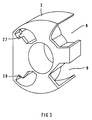
- the brushes 5; 6 have a step-shaped shoulder at their end regions which are radially remote from the commutator 7 and which accommodate the free pressure limbs 3.1; 4.1 of the brush pressure springs 3; 4 with a tangential brush pressure surface 5.1; 6.1 and a radial brush fixing surface 5.2; 6.2 to achieve a stable position of the brushes 5; 6 in their brush boxes 2.1; 2.2 between the brush contact surface 5.1; 6.1 on the one hand and the free pressure leg 3.1; 4.1 resting on this, independently of the direction of rotation of the commutator 7; a preferably by appropriate surface curvature of the brush pressure surface punctiform pressure force transmission eccentric to the longitudinal direction of brush symmetry is guaranteed within their play in the brush boxes 2.1; 2.2; this stable placement of the brushes 5; 6 within their brush boxes 2.1; 2.2 is ensured by the design of the surface curvature of the brush contact surface 5.1; 6.1 over the entire operating time of the brushes 5.6 placed at an angle to the brushes
- the brush plate 2 or the brush boxes 2.1; 2.2 or the pin-shaped brush pressure spring receptacles 2.3; 2.4 or the fixing tabs 2.5; 2.6 or fixing lugs 2.7; 2.8 or the stop tongues 2.51; 2.61 or the are in a manner which is advantageous in terms of production and assembly technology
- Suppressor choke receiving pockets 8 or the thermo-guard receiving pockets 9 are parts of a plastic injection molded part that can only be produced with axially pullable molds.
Landscapes
- Engineering & Computer Science (AREA)
- Power Engineering (AREA)
- Motor Or Generator Current Collectors (AREA)
- Motor Or Generator Frames (AREA)
Priority Applications (4)
| Application Number | Priority Date | Filing Date | Title |
|---|---|---|---|
| DE9302459U DE9302459U1 (de) | 1993-02-19 | 1993-02-19 | Bürstenhalteranordnung für einen Kommutatormotor |
| ES93102672T ES2090732T3 (es) | 1993-02-19 | 1993-02-19 | Disposicion de portaescobillas para un motor de conmutador. |
| DE59303441T DE59303441D1 (de) | 1993-02-19 | 1993-02-19 | Bürstenhalteranordnung für einen Kommutatormotor |
| EP93102672A EP0612136B1 (fr) | 1993-02-19 | 1993-02-19 | Dispositif porte-balais pour un moteur à commutateur |
Applications Claiming Priority (2)
| Application Number | Priority Date | Filing Date | Title |
|---|---|---|---|
| DE9302459U DE9302459U1 (de) | 1993-02-19 | 1993-02-19 | Bürstenhalteranordnung für einen Kommutatormotor |
| EP93102672A EP0612136B1 (fr) | 1993-02-19 | 1993-02-19 | Dispositif porte-balais pour un moteur à commutateur |
Publications (2)
| Publication Number | Publication Date |
|---|---|
| EP0612136A1 true EP0612136A1 (fr) | 1994-08-24 |
| EP0612136B1 EP0612136B1 (fr) | 1996-08-14 |
Family
ID=25960515
Family Applications (1)
| Application Number | Title | Priority Date | Filing Date |
|---|---|---|---|
| EP93102672A Expired - Lifetime EP0612136B1 (fr) | 1993-02-19 | 1993-02-19 | Dispositif porte-balais pour un moteur à commutateur |
Country Status (3)
| Country | Link |
|---|---|
| EP (1) | EP0612136B1 (fr) |
| DE (2) | DE59303441D1 (fr) |
| ES (1) | ES2090732T3 (fr) |
Cited By (3)
| Publication number | Priority date | Publication date | Assignee | Title |
|---|---|---|---|---|
| EP0724323A1 (fr) * | 1995-01-18 | 1996-07-31 | Siemens Aktiengesellschaft | Moteur à collecteur pour l'entraînement du ventilateur d'un véhicule |
| ES2119717A1 (es) * | 1997-01-27 | 1998-10-01 | Rodriguez Arturo Conde | Dispositivo elevador del n-de r.p.m. para motores electricos de escobillas o carbones sujetas por lenguetas metalicas. |
| CN103023224A (zh) * | 2012-11-29 | 2013-04-03 | 苏州博德自动化科技有限公司 | 一种转子换向器自动压入机的压入力量传感装置 |
Citations (5)
| Publication number | Priority date | Publication date | Assignee | Title |
|---|---|---|---|---|
| DE836970C (de) * | 1950-09-14 | 1952-04-17 | Siemens Ag | Stromabnehmer fuer elektrische Maschinen mit konzentrisch um eine Drehachse gekruemmtem Kontaktstueck, insbesondere Kohlebuerste |
| DE2055610A1 (de) * | 1970-11-12 | 1972-05-18 | Siemens Ag | Burstenanordnung fur eine elektrische Maschine |
| DE2461390A1 (de) * | 1974-12-24 | 1976-07-08 | Airborne Mfg Co | Elektromotor |
| EP0105392A2 (fr) * | 1982-09-29 | 1984-04-18 | Siemens Aktiengesellschaft | Boîte porte-balai pour un électromoteur à commutateur |
| WO1991003857A1 (fr) * | 1989-08-31 | 1991-03-21 | Siemens Aktiengesellschaft | Moteur a bague ou a collecteur |
-
1993
- 1993-02-19 DE DE59303441T patent/DE59303441D1/de not_active Expired - Fee Related
- 1993-02-19 ES ES93102672T patent/ES2090732T3/es not_active Expired - Lifetime
- 1993-02-19 EP EP93102672A patent/EP0612136B1/fr not_active Expired - Lifetime
- 1993-02-19 DE DE9302459U patent/DE9302459U1/de not_active Expired - Lifetime
Patent Citations (5)
| Publication number | Priority date | Publication date | Assignee | Title |
|---|---|---|---|---|
| DE836970C (de) * | 1950-09-14 | 1952-04-17 | Siemens Ag | Stromabnehmer fuer elektrische Maschinen mit konzentrisch um eine Drehachse gekruemmtem Kontaktstueck, insbesondere Kohlebuerste |
| DE2055610A1 (de) * | 1970-11-12 | 1972-05-18 | Siemens Ag | Burstenanordnung fur eine elektrische Maschine |
| DE2461390A1 (de) * | 1974-12-24 | 1976-07-08 | Airborne Mfg Co | Elektromotor |
| EP0105392A2 (fr) * | 1982-09-29 | 1984-04-18 | Siemens Aktiengesellschaft | Boîte porte-balai pour un électromoteur à commutateur |
| WO1991003857A1 (fr) * | 1989-08-31 | 1991-03-21 | Siemens Aktiengesellschaft | Moteur a bague ou a collecteur |
Cited By (3)
| Publication number | Priority date | Publication date | Assignee | Title |
|---|---|---|---|---|
| EP0724323A1 (fr) * | 1995-01-18 | 1996-07-31 | Siemens Aktiengesellschaft | Moteur à collecteur pour l'entraînement du ventilateur d'un véhicule |
| ES2119717A1 (es) * | 1997-01-27 | 1998-10-01 | Rodriguez Arturo Conde | Dispositivo elevador del n-de r.p.m. para motores electricos de escobillas o carbones sujetas por lenguetas metalicas. |
| CN103023224A (zh) * | 2012-11-29 | 2013-04-03 | 苏州博德自动化科技有限公司 | 一种转子换向器自动压入机的压入力量传感装置 |
Also Published As
| Publication number | Publication date |
|---|---|
| DE9302459U1 (de) | 1993-12-16 |
| ES2090732T3 (es) | 1996-10-16 |
| EP0612136B1 (fr) | 1996-08-14 |
| DE59303441D1 (de) | 1996-09-19 |
Similar Documents
| Publication | Publication Date | Title |
|---|---|---|
| EP0384014B1 (fr) | Dispositif pour positionner un support de bobine dans un boîtier en forme de pot | |
| EP1460747A1 (fr) | Support de palier et carcasse d'un moteur électrique | |
| DE3629634C2 (fr) | ||
| EP0586723A1 (fr) | Porte-balais à amortissement de bruit, en particulier pour un petit moteur à collecteur | |
| EP0257407A1 (fr) | Machine électrique, en particulier moteur électrique | |
| EP0058234A2 (fr) | Stator pour une machine électrique excitée par aimant permanent | |
| DE102007005737A1 (de) | Kopfstützensystem für einen Fahrzeugsitz | |
| DE69406824T2 (de) | Bürstenanordnung für Motoren | |
| EP1108150A1 (fr) | Moteur a palier lisse, en particulier palier concave, pour un arbre de rotor dote d'un reglage du jeu axial et procede de reglage du jeu axial | |
| DE10148705A1 (de) | Bürstenhaltesystem und Antriebseinrichtung | |
| EP0612136B1 (fr) | Dispositif porte-balais pour un moteur à commutateur | |
| DE2553114A1 (de) | Fuehleinheit fuer die drehgeschwindigkeit eines rades | |
| DE2839600A1 (de) | Elektro-motor | |
| DE4442634B4 (de) | Vorrichtung zum Befestigen eines Einzelspulenzündsystems mit dem Zylinderkopf einer Brennkraftmaschine | |
| DE3227199A1 (de) | Elektromotor, insbesondere zum antreiben von hilfsaggregaten in kraftfahrzeugen | |
| DE971979C (de) | Elektrische Maschine, insbesondere Kleinelektromotor, mit mindestens einem Schleifkontakt und mit einer senkrecht zur Ankerachse im Maschinengehaeuse befestigten, als Schleifkontakttraeger dienenden Isolierstoffplatte | |
| DE1284505B (de) | Anschlusskasten fuer elektrische Geraete | |
| DE3842223C2 (de) | Elektromotor, insbesondere elektrischer Kleinmotor | |
| DE3629138C2 (fr) | ||
| DE10158963A1 (de) | Außenläufermotor | |
| EP0319459B1 (fr) | Connexion pour câble coaxial, en particulier pour des antennes | |
| DE8128614U1 (de) | Geräuscharmer Bürstenhalter, insbesondere für einen Kommutator-Kleinmotor | |
| DE3008772A1 (de) | Zigarettenanzuender, insbesondere fuer kraftfahrzeuge | |
| DE2648618C3 (de) | Vorrichtung zur Befestigung eines zusätzlichen Schalterteiles auf einem Lenkstockschalter | |
| DE19718161A1 (de) | Elektromotor mit außen am Motorgehäuse angeordnetem Feststecker |
Legal Events
| Date | Code | Title | Description |
|---|---|---|---|
| PUAI | Public reference made under article 153(3) epc to a published international application that has entered the european phase |
Free format text: ORIGINAL CODE: 0009012 |
|
| AK | Designated contracting states |
Kind code of ref document: A1 Designated state(s): DE ES FR GB IT |
|
| 17P | Request for examination filed |
Effective date: 19940915 |
|
| 17Q | First examination report despatched |
Effective date: 19950828 |
|
| GRAG | Despatch of communication of intention to grant |
Free format text: ORIGINAL CODE: EPIDOS AGRA |
|
| GRAH | Despatch of communication of intention to grant a patent |
Free format text: ORIGINAL CODE: EPIDOS IGRA |
|
| GRAH | Despatch of communication of intention to grant a patent |
Free format text: ORIGINAL CODE: EPIDOS IGRA |
|
| GRAA | (expected) grant |
Free format text: ORIGINAL CODE: 0009210 |
|
| AK | Designated contracting states |
Kind code of ref document: B1 Designated state(s): DE ES FR GB IT |
|
| REF | Corresponds to: |
Ref document number: 59303441 Country of ref document: DE Date of ref document: 19960919 |
|
| REG | Reference to a national code |
Ref country code: ES Ref legal event code: FG2A Ref document number: 2090732 Country of ref document: ES Kind code of ref document: T3 |
|
| ITF | It: translation for a ep patent filed | ||
| GBT | Gb: translation of ep patent filed (gb section 77(6)(a)/1977) |
Effective date: 19961018 |
|
| REG | Reference to a national code |
Ref country code: ES Ref legal event code: FG2A Ref document number: 2090732 Country of ref document: ES Kind code of ref document: T3 |
|
| ET | Fr: translation filed | ||
| PLBE | No opposition filed within time limit |
Free format text: ORIGINAL CODE: 0009261 |
|
| STAA | Information on the status of an ep patent application or granted ep patent |
Free format text: STATUS: NO OPPOSITION FILED WITHIN TIME LIMIT |
|
| 26N | No opposition filed | ||
| PGFP | Annual fee paid to national office [announced via postgrant information from national office to epo] |
Ref country code: GB Payment date: 20010208 Year of fee payment: 9 |
|
| PGFP | Annual fee paid to national office [announced via postgrant information from national office to epo] |
Ref country code: ES Payment date: 20010222 Year of fee payment: 9 |
|
| PGFP | Annual fee paid to national office [announced via postgrant information from national office to epo] |
Ref country code: FR Payment date: 20010223 Year of fee payment: 9 |
|
| REG | Reference to a national code |
Ref country code: GB Ref legal event code: IF02 |
|
| PG25 | Lapsed in a contracting state [announced via postgrant information from national office to epo] |
Ref country code: GB Free format text: LAPSE BECAUSE OF NON-PAYMENT OF DUE FEES Effective date: 20020219 |
|
| PG25 | Lapsed in a contracting state [announced via postgrant information from national office to epo] |
Ref country code: ES Free format text: LAPSE BECAUSE OF NON-PAYMENT OF DUE FEES Effective date: 20020220 |
|
| GBPC | Gb: european patent ceased through non-payment of renewal fee |
Effective date: 20020219 |
|
| PG25 | Lapsed in a contracting state [announced via postgrant information from national office to epo] |
Ref country code: FR Free format text: LAPSE BECAUSE OF NON-PAYMENT OF DUE FEES Effective date: 20021031 |
|
| REG | Reference to a national code |
Ref country code: FR Ref legal event code: ST |
|
| REG | Reference to a national code |
Ref country code: ES Ref legal event code: FD2A Effective date: 20031022 |
|
| PG25 | Lapsed in a contracting state [announced via postgrant information from national office to epo] |
Ref country code: IT Free format text: LAPSE BECAUSE OF NON-PAYMENT OF DUE FEES;WARNING: LAPSES OF ITALIAN PATENTS WITH EFFECTIVE DATE BEFORE 2007 MAY HAVE OCCURRED AT ANY TIME BEFORE 2007. THE CORRECT EFFECTIVE DATE MAY BE DIFFERENT FROM THE ONE RECORDED. Effective date: 20050219 |
|
| PGFP | Annual fee paid to national office [announced via postgrant information from national office to epo] |
Ref country code: DE Payment date: 20060424 Year of fee payment: 14 |
|
| PG25 | Lapsed in a contracting state [announced via postgrant information from national office to epo] |
Ref country code: DE Free format text: LAPSE BECAUSE OF NON-PAYMENT OF DUE FEES Effective date: 20070901 |