EP0614024B1 - Actionneur pour un frein à disque - Google Patents
Actionneur pour un frein à disque Download PDFInfo
- Publication number
- EP0614024B1 EP0614024B1 EP94103230A EP94103230A EP0614024B1 EP 0614024 B1 EP0614024 B1 EP 0614024B1 EP 94103230 A EP94103230 A EP 94103230A EP 94103230 A EP94103230 A EP 94103230A EP 0614024 B1 EP0614024 B1 EP 0614024B1
- Authority
- EP
- European Patent Office
- Prior art keywords
- contour
- brake
- clamping unit
- unit according
- clamping
- Prior art date
- Legal status (The legal status is an assumption and is not a legal conclusion. Google has not performed a legal analysis and makes no representation as to the accuracy of the status listed.)
- Expired - Lifetime
Links
- 230000006835 compression Effects 0.000 claims description 4
- 238000007906 compression Methods 0.000 claims description 4
- 230000036316 preload Effects 0.000 claims 2
- 238000005096 rolling process Methods 0.000 description 3
- 238000003860 storage Methods 0.000 description 2
- 230000007704 transition Effects 0.000 description 2
- 230000005540 biological transmission Effects 0.000 description 1
- 230000006735 deficit Effects 0.000 description 1
- 238000006073 displacement reaction Methods 0.000 description 1
- 230000000694 effects Effects 0.000 description 1
- 238000005304 joining Methods 0.000 description 1
- 238000004519 manufacturing process Methods 0.000 description 1
- 238000000034 method Methods 0.000 description 1
- 238000006386 neutralization reaction Methods 0.000 description 1
- 230000010355 oscillation Effects 0.000 description 1
- 238000011144 upstream manufacturing Methods 0.000 description 1
Images

Classifications
-
- F—MECHANICAL ENGINEERING; LIGHTING; HEATING; WEAPONS; BLASTING
- F16—ENGINEERING ELEMENTS AND UNITS; GENERAL MEASURES FOR PRODUCING AND MAINTAINING EFFECTIVE FUNCTIONING OF MACHINES OR INSTALLATIONS; THERMAL INSULATION IN GENERAL
- F16D—COUPLINGS FOR TRANSMITTING ROTATION; CLUTCHES; BRAKES
- F16D65/00—Parts or details
- F16D65/14—Actuating mechanisms for brakes; Means for initiating operation at a predetermined position
- F16D65/16—Actuating mechanisms for brakes; Means for initiating operation at a predetermined position arranged in or on the brake
- F16D65/18—Actuating mechanisms for brakes; Means for initiating operation at a predetermined position arranged in or on the brake adapted for drawing members together, e.g. for disc brakes
- F16D65/183—Actuating mechanisms for brakes; Means for initiating operation at a predetermined position arranged in or on the brake adapted for drawing members together, e.g. for disc brakes with force-transmitting members arranged side by side acting on a spot type force-applying member
-
- F—MECHANICAL ENGINEERING; LIGHTING; HEATING; WEAPONS; BLASTING
- F16—ENGINEERING ELEMENTS AND UNITS; GENERAL MEASURES FOR PRODUCING AND MAINTAINING EFFECTIVE FUNCTIONING OF MACHINES OR INSTALLATIONS; THERMAL INSULATION IN GENERAL
- F16D—COUPLINGS FOR TRANSMITTING ROTATION; CLUTCHES; BRAKES
- F16D2121/00—Type of actuator operation force
- F16D2121/14—Mechanical
-
- F—MECHANICAL ENGINEERING; LIGHTING; HEATING; WEAPONS; BLASTING
- F16—ENGINEERING ELEMENTS AND UNITS; GENERAL MEASURES FOR PRODUCING AND MAINTAINING EFFECTIVE FUNCTIONING OF MACHINES OR INSTALLATIONS; THERMAL INSULATION IN GENERAL
- F16D—COUPLINGS FOR TRANSMITTING ROTATION; CLUTCHES; BRAKES
- F16D2125/00—Components of actuators
- F16D2125/18—Mechanical mechanisms
- F16D2125/20—Mechanical mechanisms converting rotation to linear movement or vice versa
- F16D2125/22—Mechanical mechanisms converting rotation to linear movement or vice versa acting transversely to the axis of rotation
- F16D2125/28—Cams; Levers with cams
- F16D2125/32—Cams; Levers with cams acting on one cam follower
Definitions
- the invention relates to an application device for a disc brake, in particular for a sliding caliper disc brake, with an application shaft arranged parallel to the brake disc plane, which is located on the side facing the brake disc via a first contour describing a circular arc and mounted in a corresponding bearing shell on a thrust piece movable against the brake disc and on the side facing away from the brake disc is supported via a second contour which is eccentric to the first contour on an element to which the pressure piece is relatively movable.
- a clamping device of the type described above is known from DE 40 32 885 A1.
- the first contour and the bearing shell intermesh in such a way that the clamping shaft also serves as a bearing for the pressure piece can serve, which is why a storage or guidance of the pressure piece is unnecessary.
- the second contour is designed in the form of a circular arc in the known clamping device. Since the two arcs, namely that of the first contour and that of the second contour are eccentric to one another, the thrust piece performs an oscillating movement in a plane perpendicular to the plane of the brake disc when the application shaft is rotated.
- the brake shoes are correspondingly inclined during braking, which on the one hand suffers the braking process itself and on the other hand also results in uneven wear of the brake pads.
- the application shaft on one side and the pressure piece on the other side are each decoupled by suitable measures, so that there is no pendulum movement of the pressure piece comes.
- the decoupling is carried out by a ball, by a slidable plate or by a plunger between the application shaft and the pressure piece.
- the decoupling means that the clamping shaft and the pressure piece cannot hold or guide one another, which is why flexible brackets for the clamping shaft are required for the clamping devices according to the prior art, cf. for example spring 86 in DE 26 14 321 C2. Due to the decoupling, the position of the clamping shaft is unstable, which makes the clamping uneven.
- the invention has for its object to improve an application device of the type mentioned in that pressure piece and application shaft hold or guide each other, but still no impairment of the braking effect and there is no uneven wear of the brake pads due to a pendulum movement.
- the object is achieved in that the second contour is composed of at least two arcs, the centers and radii of which are selected such that the amount of movement of the thrust piece occurring when the application shaft is rotated is minimized relative to the application shaft and in the direction parallel to the brake disc plane .
- the invention is based on the astonishingly simple finding that the relative movement can be kept so small or eliminated by a suitable choice of the second contour that an interlocking of the application shaft and the pressure piece for mounting or guiding the pressure piece through the application shaft or vice versa to no disadvantages leads when braking or when the brake pads wear.
- the clamping device according to the invention is more compact and requires fewer individual parts.
- adjacent circular arcs of the second contour touch each other at the common border. This "smooth" transition from one circular arc to the other prevents “steps” or other discontinuities from occurring when the tension is applied.
- the second contour is a cycloid.
- a cycloid can be understood as a curve made up of an infinite number of arcs. If the second contour has the shape of a cycloid, no movement of the pressure piece occurs when the tensioning shaft is turned relative to the application shaft and in the direction parallel to the brake disc axis.
- the second contour can be formed from two arcs, one of which is the idle stroke, i.e. the stroke to overcome the brake release play, and one is assigned to the power stroke.
- the common limit lies precisely at the transition between the idle stroke and the power stroke.
- the circular arc associated with the idle stroke of the second contour has a smaller radius than the circular arc associated with the power stroke. Since the surface pressure between the second contour and the element to which the pressure piece can be moved is still relatively low in the idle stroke, it does not have any disadvantage if the pressure piece in this area moves slightly in the direction parallel to the brake disc axis. The surface pressure is also relatively low in this area, so that the smaller radius is not disadvantageous either.
- the application shaft is then supported with a circular arc with a larger radius, which is also necessary in view of the increased surface pressure. At the same time, the movement of the pressure piece relative to the application shaft and in the direction parallel to the brake disc plane is smaller with a larger radius.
- a rotary bearing between the first contour and the bearing shell can be provided according to the invention.
- the second contour is axially longer than the first contour.
- the pressure piece in the brake caliper be guided on all sides in dome-shaped guides with little bearing play. This ensures radial and lateral guidance of the pressure piece.
- a prestress can be provided in the direction of releasing the brake, the prestress preferably having at least one compression spring that prestresses the pressure piece in the direction away from the brake disc.
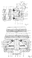
- the disc brake shown in the drawing is a sliding caliper disc brake. It has a brake caliper 1 which overlaps a brake disc 2 with its two legs in the usual way. Brake pads 3, 4 are guided and supported on brake pads 5 in a brake carrier (not shown) or in the brake caliper 1 on both sides of the brake disc.
- the brake caliper 1 is displaceably mounted transversely to the brake disc in a manner not shown with the aid of guide means.
- the brake caliper 1 has an application device 6 on one side for actuating the brake.
- the application device essentially consists of a brake lever 7, which is connected to an application shaft 8 arranged parallel to the brake disc plane, and a pressure piece 9 which is displaceable in the caliper 1 and into which a pressure spindle 10 is screwed in the center of the plane of the brake axis A of the application device 6. Facing the brake disc 2, the pressure spindle 10 is coupled to a pressure part 11 which is supported on the lining carrier 5. The pressure part 11 extends approximately over the covering width.
- the pressure piece 9 is guided in steep dome-shaped guides 25 on all sides with little bearing play in the brake caliper 1.
- a cover 12 is fixed on the brake caliper 1. A connection to a brake cylinder, not shown, is thus established.
- the brake lever 7 establishes the connection between the brake cylinder or a brake linkage, also not shown, and the application shaft 8.
- a support plate 14 is attached in the caliper 1 in a plane parallel to the brake disc 2. It has a support surface 15 on which the application shaft 8 is supported.
- the support plate 14 can be divided or in one piece. Their length depends on the one below explained execution of the application shaft 8 from. 2 and 3, a free passage 16 for the axial passage of the pressure spindle 10 is formed in the central region of the application shaft 8.
- the application shaft 8 can also be designed without a free passage 16, that is to say in a continuous contour, provided that the application takes place, for example, via two pressure spindles 10, each of which is screwed into the outer end of the pressure piece 9.
- the particularly compact design of the application device enables the creation of a free space 26 on the side of the application shaft 8 facing away from the brake disk and thus in the force-free area of the brake.
- the free space can serve to accommodate an adjusting device, as described, for example, in a patent application filed with the same priority.
- the adjustment device can therefore be installed as a prefabricated unit. It is exposed to little stress.
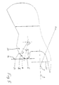
- FIG. 3 and 4 show the contour of the application shaft 8.
- FIG. 5 shows an enlargement of the detail Z.
- the brake shaft 8 has an approximately semi-cylindrical shoulder 17 with radius R facing the brake disc.
- the center point P of the cylinder lies on the brake axis A.
- the lateral surface of the extension 17 extends parallel to the rotational axis which moves in accordance with the rotation (distance P 1 , P 2 see below) of the application shaft 8.
- the extension 17 is connected to an intermediate rotary bearing 18 ( Rolling and / or plain bearings) are mounted in corresponding inner cylindrical surfaces 19 of the pressure piece 9.
- the shoulder and the inner cylindrical surface can also be formed in reverse on the parts 8, 9, but the embodiment described is preferred.
- the outer surface of a pressure bar 20 which extends parallel to the shoulder 17 and lies against the supporting surface 15 is formed by a curve 21 which results from the joining of a plurality of curve sections (here 2).
- the first section I is part of a circular arc with the radius R 1 around the point P 1 , this point not coinciding with the point P.
- the second section II adjoining the first section I is part of a circular arc with the radius R 2 around P 2 . P 2 does not coincide with P or with P 1 .
- the radius R 1 is smaller than the radius R 2 .
- the radii R 1 and R 2 and the respective position of the points P 2 and P 1 are chosen so that the two arcs touch each other in a boundary line B.
- curve 21 of the lateral surface of pressure bar 20 achieves the following advantage in particular.
- the lateral surface of the first curve section I with the smaller radius R 1 rolls radially inward along the supporting surface 15 on the brake caliper up to the limit line B. Since the surface pressure between the jacket and the Support surface is still relatively small in the idle stroke, it does not have a disadvantage if the eccentric in this area makes a slight upward movement on a circular arc section in the direction of a vertical 22.
- the pressure piece 9 is axially displaced in the direction of the brake disc 2.
- the axis of rotation of the application shaft 8 continuously "moves" radially inwards faster than the eccentric center on the circular arc in the vertical 22 direction. Since this means that the vertical is not exceeded by a "neutralization” of the pendulum movement in the power stroke ⁇ , there is an approximately linear tensioning along the brake axis A in the direction of the brake disc 2 without any tension in the caliper guide 25.
- the arrangement of the pressure bar 20 with respect to the support surface 15 of the brake caliper 1 also has the advantage that tolerances with respect to the rotary bearing caused by manufacturing and assembly are compensated for.
- the embodiment described is preferred.
- the clamping (pressure piece, bearing, clamping shaft) is in the direction Support surface 15 and thus the brake lever 7 biased against a saddle system 24.
- Fig. 2 shows that the pressure bar 20 is longer than the pivot bearing 18. On the one hand, this corresponds to the storage loads. On the other hand, this allows optimal use of space within the saddle. 3, in particular the design and mounting of the application shaft, can of course also be applied to a hydraulic disc brake with mechanical actuation as a parking brake. Since, in this application, smaller surface pressures occur against the saddle support due to smaller application forces, the course of the curve sections I, II can also be reversed, that is to say first the larger and then the smaller radius, to form a common curve 21. A very precise linear application movement of the pressure piece 9 is thereby achieved.
Landscapes
- Engineering & Computer Science (AREA)
- General Engineering & Computer Science (AREA)
- Mechanical Engineering (AREA)
- Braking Arrangements (AREA)
Claims (10)
- Actionneur pour frein à disque, notamment pour frein à disque en forme de selle coulissante, avec un arbre actionneur (8) disposé parallèlement au plan du disque de freinage et prenant appui, du côté adjacent au disque de freinage, sur un organe de pression (9) déplaçable contre le disque de freinage (2), par l'intermédiaire d'un premier profil (10) décrivant un arc de cercle et logé dans une cuvette de palier (19) correspondant, et, du côté éloigné du disque de freinage, par l'intermédaire d'un deuxième profil (21) excentrique par rapport au premier profil (17), sur un élément (14) par rapport auquel l'organe de pression (9), est mobile,
caractérisé en ce que,
le deuxième profil (21) se compose d'au moins deux arcs de cercle (I, II) dont les centres (P1, P2) et les rayons (R1, R2) sont choisis de telle façon que la quantité de mouvement d'un mouvement se produisant lors d'une rotation de l'arbre actionneur (8) est minimisé par rapport à l'arbre actionneur (8) et dans une direction parallèle au plan du disque de freinage. - Actionneur selon la revendication 1, caractérisé en ce que les arcs de cercle voisins (I, II) du deuxième profil (21) sont tangents, mutuellement, à la ligne de délimitation commune (B).
- Actionneur selon la revendication 1 ou 2, caractérisé en ce que le deuxième profil est une cycloïde.
- Actionneur selon la revendication 1 ou 2, caractérisé en ce que le deuxième profil (21) est formé par deux arcs de cercle (I, II) dont l'un est associé à la course à vide (α) et l'autre à la course motrice (β).
- Actionneur selon la revendication 4, caractérisé en ce que l'arc de cercle (I) associé à la course à vide (α), du second profil (21) a un rayon (R1) inférieur à celui de l'arc de cercle (II) associé à la course motrice (β).
- Actionneur selon l'une des revendications précédentes, caractérisé par un coussinnet de pivotement (18) entre le premier profil (17) et la cuvette de palier (19).
- Actionneur selon l'une des revendications précédentes, caractérisé en ce que le deuxième profil (21) est axialement plus long que le premier profil (17).
- Actionneur selon l'une des revendications précédentes, caractérisé en ce que l'organe de pression (9) est guidée sur tous les côtés dans la selle de freinage (1) dans des guidages latérales en forme de calottes (25).
- Actionneur selon l'une des revendications précédentes, caractérisé par une précontrainte (23) dans la direction d'un relâchement du frein.
- Actionneur selon la revendication 9, caractérisé en ce que la précontrainte comprend un ressort de pression (23) sollicitant l'organe de pression (2) dans une direction au loin du disque de freinage (2).
Applications Claiming Priority (2)
| Application Number | Priority Date | Filing Date | Title |
|---|---|---|---|
| DE4307019A DE4307019B4 (de) | 1993-03-05 | 1993-03-05 | Zuspannvorrichtung für eine Scheibenbremse |
| DE4307019 | 1993-03-05 |
Publications (2)
| Publication Number | Publication Date |
|---|---|
| EP0614024A1 EP0614024A1 (fr) | 1994-09-07 |
| EP0614024B1 true EP0614024B1 (fr) | 1996-09-04 |
Family
ID=6482075
Family Applications (1)
| Application Number | Title | Priority Date | Filing Date |
|---|---|---|---|
| EP94103230A Expired - Lifetime EP0614024B1 (fr) | 1993-03-05 | 1994-03-03 | Actionneur pour un frein à disque |
Country Status (3)
| Country | Link |
|---|---|
| US (1) | US5400875A (fr) |
| EP (1) | EP0614024B1 (fr) |
| DE (1) | DE4307019B4 (fr) |
Cited By (2)
| Publication number | Priority date | Publication date | Assignee | Title |
|---|---|---|---|---|
| EP1359337A2 (fr) | 2002-04-29 | 2003-11-05 | Wabco Radbremsen GmbH | Actionneur pour frein à disque |
| DE102015101468A1 (de) | 2015-02-02 | 2016-08-04 | Bpw Bergische Achsen Kg | Scheibenbremse für ein Nutzfahrzeugrad |
Families Citing this family (30)
| Publication number | Priority date | Publication date | Assignee | Title |
|---|---|---|---|---|
| US5622240A (en) * | 1992-09-08 | 1997-04-22 | Knorr Bremse Systeme Fuer Nutzfahrzeuge | Compressed-air actuated disk brake |
| DE4308704A1 (de) * | 1993-03-18 | 1994-09-22 | Knorr Bremse Ag | Druckluftbetätigte Scheibenbremse |
| DE4416175A1 (de) | 1994-05-06 | 1995-11-09 | Perrot Bremsen Gmbh | Scheibenbremse |
| DE4430258C1 (de) | 1994-08-25 | 1996-01-04 | Perrot Bremsen Gmbh | Zuspannvorrichtung für eine Scheibenbremse |
| SE505339C2 (sv) † | 1994-10-24 | 1997-08-11 | Haldex Ab | Skivbromstång |
| DE19507308A1 (de) * | 1995-03-02 | 1996-09-05 | Perrot Bremsen Gmbh | Scheibenbremse |
| DE19515019A1 (de) * | 1995-04-24 | 1996-10-31 | Perrot Bremsen Gmbh | Scheibenbremse |
| DE19515063C2 (de) * | 1995-04-27 | 2002-06-06 | Knorr Bremse Systeme | Scheibenbremse für Fahrzeuge, insbesondere Straßenfahrzeuge |
| DE19525048A1 (de) * | 1995-07-10 | 1997-01-16 | Perrot Bremsen Gmbh | Scheibenbremse |
| SE516496C2 (sv) * | 2000-04-03 | 2002-01-22 | Haldex Brake Prod Ab | Bromsmekanism |
| SE522395C2 (sv) | 2000-05-31 | 2004-02-03 | Haldex Brake Prod Ab | Modulformad bromsmekanism |
| SE522332C2 (sv) | 2000-05-31 | 2004-02-03 | Haldex Brake Prod Ab | Förfarande för att montera en bromsmekanism i ett bromsok samt ett sådant bromsok |
| SE516495C2 (sv) | 2000-05-31 | 2002-01-22 | Haldex Brake Prod Ab | Bromsmekanism och bromsok för en skivbroms |
| DE10232961B4 (de) * | 2002-07-19 | 2007-06-14 | Wabco Perrot Bremsen Gmbh | Scheibenbremse, insbesondere für Landfahrzeuge |
| DE10242397B3 (de) * | 2002-09-12 | 2004-03-18 | Haldex Brake Products Ab | Scheibenbremse |
| DE102005046003B4 (de) * | 2005-09-23 | 2016-08-25 | Bpw Bergische Achsen Kg | Radbremse |
| DE102005056065B3 (de) * | 2005-11-24 | 2007-08-23 | Knorr-Bremse Systeme für Nutzfahrzeuge GmbH | Scheibenbremse, insbesondere für ein Nutzfahrzeug |
| DE102006003294A1 (de) * | 2006-01-23 | 2007-08-02 | Bpw Bergische Achsen Kg | Scheibenbremse |
| DE102006033254B3 (de) * | 2006-07-18 | 2007-09-13 | Wabco Radbremsen Gmbh | Scheibenbremse, insbesondere für Nutzfahrzeuge, sowie Betätigungszylinder einer solchen Scheibenbremse |
| EP2297477B1 (fr) * | 2008-07-04 | 2012-03-28 | KNORR-BREMSE Systeme für Nutzfahrzeuge GmbH | Frein à disque à actionnement pneumatique et cylindre de frein |
| DE102009013005C5 (de) * | 2009-03-13 | 2013-05-02 | Knorr-Bremse Systeme für Nutzfahrzeuge GmbH | Doppelkolben-Scheibenbremse |
| EP2643610B2 (fr) | 2010-11-26 | 2019-02-27 | Wabco Radbremsen GmbH | Frein à disque |
| US8845499B1 (en) | 2011-12-09 | 2014-09-30 | Donald Jeffrey Boatwright | Personal force resistance cable exercise device, force resistance assembly, and method of exercising |
| US9700753B1 (en) | 2011-12-09 | 2017-07-11 | Donald Jeffrey Boatwright | Personal force resistance cable exercise device, force resistance assembly, and method of exercising |
| US10143880B1 (en) | 2011-12-09 | 2018-12-04 | Donald Jeffrey Boatwright | Cable exercise device and method |
| DE102012009424A1 (de) * | 2012-05-11 | 2013-11-14 | Knorr-Bremse Systeme für Nutzfahrzeuge GmbH | Scheibenbremse für ein Nutzfahrzeug |
| EP2959096B1 (fr) | 2013-02-21 | 2018-05-16 | National Oilwell Varco, L.P. | Système de surveillance d'un bloc obturateur de puits et son procédé d'utilisation |
| WO2015004696A1 (fr) * | 2013-07-11 | 2015-01-15 | 株式会社Tbk | Dispositif de frein à disque |
| DE102013011657B4 (de) * | 2013-07-12 | 2016-08-25 | Knorr-Bremse Systeme für Nutzfahrzeuge GmbH | Scheibenbremse für ein Nutzfahrzeug |
| AT522087B1 (de) * | 2019-04-24 | 2020-08-15 | Greenbrakes Gmbh | Bremsvorrichtung |
Family Cites Families (8)
| Publication number | Priority date | Publication date | Assignee | Title |
|---|---|---|---|---|
| US3332521A (en) * | 1965-08-11 | 1967-07-25 | Bendix Corp | Closed loop type disc brake |
| US3830343A (en) * | 1972-12-12 | 1974-08-20 | Goodrich Co B F | Disc brake with adjustable cam operator and thrust distributer |
| CA1030881A (fr) * | 1975-04-02 | 1978-05-09 | Donald D. Johannesen | Frein a disque a commande mecanique |
| US4036329A (en) * | 1975-11-12 | 1977-07-19 | Rockwell International Corporation | Disc brake with rotary cam actuated reciprocating pistons |
| DE3411745A1 (de) * | 1984-03-30 | 1985-10-10 | Alfred Teves Gmbh, 6000 Frankfurt | Mechanische betaetigungsvorrichtung |
| DE3716202C3 (de) * | 1987-05-14 | 2000-03-09 | Knorr Bremse Systeme | Scheibenbremse für Fahrzeuge |
| DE4032885A1 (de) * | 1990-10-17 | 1992-04-23 | Knorr Bremse Ag | Scheibenbremse fuer fahrzeuge, insbesondere strassenfahrzeuge |
| DE4217983A1 (de) * | 1991-06-26 | 1993-01-28 | Teves Gmbh Alfred | Mechanische betaetigungsvorrichtung fuer scheibenbremsen und verfahren zu deren montage |
-
1993
- 1993-03-05 DE DE4307019A patent/DE4307019B4/de not_active Expired - Lifetime
-
1994
- 1994-03-03 EP EP94103230A patent/EP0614024B1/fr not_active Expired - Lifetime
- 1994-03-07 US US08/206,672 patent/US5400875A/en not_active Expired - Lifetime
Cited By (3)
| Publication number | Priority date | Publication date | Assignee | Title |
|---|---|---|---|---|
| EP1359337A2 (fr) | 2002-04-29 | 2003-11-05 | Wabco Radbremsen GmbH | Actionneur pour frein à disque |
| DE102015101468A1 (de) | 2015-02-02 | 2016-08-04 | Bpw Bergische Achsen Kg | Scheibenbremse für ein Nutzfahrzeugrad |
| WO2016124174A1 (fr) | 2015-02-02 | 2016-08-11 | Bpw Bergische Achsen Kg | Frein à disque pour véhicule utilitaire |
Also Published As
| Publication number | Publication date |
|---|---|
| DE4307019B4 (de) | 2006-06-14 |
| DE4307019A1 (de) | 1994-09-08 |
| US5400875A (en) | 1995-03-28 |
| EP0614024A1 (fr) | 1994-09-07 |
Similar Documents
| Publication | Publication Date | Title |
|---|---|---|
| EP0614024B1 (fr) | Actionneur pour un frein à disque | |
| EP0698749B1 (fr) | Actionneur de frein à disque | |
| DE10219148C1 (de) | Linearzuspannvorrichtung für eine Scheibenbremse | |
| EP2010794B1 (fr) | Frein a disque | |
| EP0589206B1 (fr) | Dispositif d'actionnement pour un frein à disque à étrier coulissant | |
| EP0777598B1 (fr) | Ensemble etrier pour freins a disques de vehicules, notamment de vehicules sur rails | |
| DE2423299C3 (de) | Mutter für Kugelumlaufschraubgetriebe | |
| DE60003887T2 (de) | Kompakter aktuator | |
| EP0328595A1 (fr) | Cylindre compresseur | |
| WO2009050226A1 (fr) | Frein à disque | |
| WO1994005926A1 (fr) | Frein a disque commande par air comprime | |
| EP1753682B1 (fr) | Rouleau deplisseur | |
| DE1525213B2 (de) | Radialdrahtkugellager | |
| DE19644958C2 (de) | Getriebe mit stufenlos verstellbarem Übersetzungsverhältnis | |
| WO2003025413A1 (fr) | Frein a disque destine notamment a un vehicule utilitaire | |
| DE3800994A1 (de) | Presse zum kontinuierlichen herstellen von span- und faserplatten oder dergleichen | |
| EP0684403B1 (fr) | Frein à disque | |
| DE3616695C2 (de) | Teilbelag-Scheibenbremse | |
| EP0822351A2 (fr) | Système de freinage, en particulier frein à disque du type à étrier coulissant, pour véhicule automobile | |
| DE4217983A1 (de) | Mechanische betaetigungsvorrichtung fuer scheibenbremsen und verfahren zu deren montage | |
| EP1056954B1 (fr) | Joint tournant sans centre | |
| DE69705864T2 (de) | Lageraufbau | |
| EP0203279B1 (fr) | Cylindre, de préférence cylindre de contre-pression d'un cylindre gravé dont la chemise peut être courbée | |
| EP1721085B1 (fr) | Frein a disque | |
| DE102021200218A1 (de) | Schiebenockenanordnung |
Legal Events
| Date | Code | Title | Description |
|---|---|---|---|
| PUAI | Public reference made under article 153(3) epc to a published international application that has entered the european phase |
Free format text: ORIGINAL CODE: 0009012 |
|
| AK | Designated contracting states |
Kind code of ref document: A1 Designated state(s): FR GB IT SE |
|
| 17P | Request for examination filed |
Effective date: 19950209 |
|
| 17Q | First examination report despatched |
Effective date: 19951108 |
|
| GRAH | Despatch of communication of intention to grant a patent |
Free format text: ORIGINAL CODE: EPIDOS IGRA |
|
| GRAH | Despatch of communication of intention to grant a patent |
Free format text: ORIGINAL CODE: EPIDOS IGRA |
|
| GRAA | (expected) grant |
Free format text: ORIGINAL CODE: 0009210 |
|
| AK | Designated contracting states |
Kind code of ref document: B1 Designated state(s): FR GB IT SE |
|
| GBT | Gb: translation of ep patent filed (gb section 77(6)(a)/1977) |
Effective date: 19960918 |
|
| ITF | It: translation for a ep patent filed | ||
| ET | Fr: translation filed | ||
| PLBE | No opposition filed within time limit |
Free format text: ORIGINAL CODE: 0009261 |
|
| STAA | Information on the status of an ep patent application or granted ep patent |
Free format text: STATUS: NO OPPOSITION FILED WITHIN TIME LIMIT |
|
| 26N | No opposition filed | ||
| REG | Reference to a national code |
Ref country code: GB Ref legal event code: IF02 |
|
| PG25 | Lapsed in a contracting state [announced via postgrant information from national office to epo] |
Ref country code: IT Free format text: LAPSE BECAUSE OF NON-PAYMENT OF DUE FEES Effective date: 20050303 |
|
| PGRI | Patent reinstated in contracting state [announced from national office to epo] |
Ref country code: IT Effective date: 20080301 |
|
| PGFP | Annual fee paid to national office [announced via postgrant information from national office to epo] |
Ref country code: IT Payment date: 20120326 Year of fee payment: 19 Ref country code: SE Payment date: 20120313 Year of fee payment: 19 Ref country code: GB Payment date: 20120319 Year of fee payment: 19 |
|
| PGFP | Annual fee paid to national office [announced via postgrant information from national office to epo] |
Ref country code: FR Payment date: 20120417 Year of fee payment: 19 |
|
| REG | Reference to a national code |
Ref country code: SE Ref legal event code: EUG |
|
| PG25 | Lapsed in a contracting state [announced via postgrant information from national office to epo] |
Ref country code: SE Free format text: LAPSE BECAUSE OF NON-PAYMENT OF DUE FEES Effective date: 20130304 |
|
| GBPC | Gb: european patent ceased through non-payment of renewal fee |
Effective date: 20130303 |
|
| REG | Reference to a national code |
Ref country code: FR Ref legal event code: ST Effective date: 20131129 |
|
| PG25 | Lapsed in a contracting state [announced via postgrant information from national office to epo] |
Ref country code: FR Free format text: LAPSE BECAUSE OF NON-PAYMENT OF DUE FEES Effective date: 20130402 Ref country code: GB Free format text: LAPSE BECAUSE OF NON-PAYMENT OF DUE FEES Effective date: 20130303 |
|
| PG25 | Lapsed in a contracting state [announced via postgrant information from national office to epo] |
Ref country code: IT Free format text: LAPSE BECAUSE OF NON-PAYMENT OF DUE FEES Effective date: 20130303 |