EP0615314B1 - Kombination eines in ein Paneel montierbaren elektrischen Verbinders und einer Schutzkappe - Google Patents
Kombination eines in ein Paneel montierbaren elektrischen Verbinders und einer Schutzkappe Download PDFInfo
- Publication number
- EP0615314B1 EP0615314B1 EP94103697A EP94103697A EP0615314B1 EP 0615314 B1 EP0615314 B1 EP 0615314B1 EP 94103697 A EP94103697 A EP 94103697A EP 94103697 A EP94103697 A EP 94103697A EP 0615314 B1 EP0615314 B1 EP 0615314B1
- Authority
- EP
- European Patent Office
- Prior art keywords
- connector
- cap
- mounting hole
- protecting cap
- engagement
- Prior art date
- Legal status (The legal status is an assumption and is not a legal conclusion. Google has not performed a legal analysis and makes no representation as to the accuracy of the status listed.)
- Expired - Lifetime
Links
- 230000002093 peripheral effect Effects 0.000 claims description 8
- 238000003780 insertion Methods 0.000 description 8
- 230000037431 insertion Effects 0.000 description 8
- 238000005452 bending Methods 0.000 description 1
- 238000010276 construction Methods 0.000 description 1
- 239000002184 metal Substances 0.000 description 1
- 238000012986 modification Methods 0.000 description 1
- 230000004048 modification Effects 0.000 description 1
- 230000003014 reinforcing effect Effects 0.000 description 1
Images


Classifications
-
- H—ELECTRICITY
- H01—ELECTRIC ELEMENTS
- H01R—ELECTRICALLY-CONDUCTIVE CONNECTIONS; STRUCTURAL ASSOCIATIONS OF A PLURALITY OF MUTUALLY-INSULATED ELECTRICAL CONNECTING ELEMENTS; COUPLING DEVICES; CURRENT COLLECTORS
- H01R13/00—Details of coupling devices of the kinds covered by groups H01R12/70 or H01R24/00 - H01R33/00
- H01R13/44—Means for preventing access to live contacts
- H01R13/443—Dummy plugs
-
- H—ELECTRICITY
- H01—ELECTRIC ELEMENTS
- H01R—ELECTRICALLY-CONDUCTIVE CONNECTIONS; STRUCTURAL ASSOCIATIONS OF A PLURALITY OF MUTUALLY-INSULATED ELECTRICAL CONNECTING ELEMENTS; COUPLING DEVICES; CURRENT COLLECTORS
- H01R13/00—Details of coupling devices of the kinds covered by groups H01R12/70 or H01R24/00 - H01R33/00
- H01R13/46—Bases; Cases
- H01R13/52—Dustproof, splashproof, drip-proof, waterproof, or flameproof cases
- H01R13/5213—Covers
-
- H—ELECTRICITY
- H01—ELECTRIC ELEMENTS
- H01R—ELECTRICALLY-CONDUCTIVE CONNECTIONS; STRUCTURAL ASSOCIATIONS OF A PLURALITY OF MUTUALLY-INSULATED ELECTRICAL CONNECTING ELEMENTS; COUPLING DEVICES; CURRENT COLLECTORS
- H01R13/00—Details of coupling devices of the kinds covered by groups H01R12/70 or H01R24/00 - H01R33/00
- H01R13/62—Means for facilitating engagement or disengagement of coupling parts or for holding them in engagement
- H01R13/621—Bolt, set screw or screw clamp
- H01R13/6215—Bolt, set screw or screw clamp using one or more bolts
Definitions
- This invention relates to a combination of an electrical connector and a protecting cap for such a connector, especially a panel-mounted electrical connector including a cylindrical portion holding therein terminals and mounted in a mounting hole formed in a panel with an open end of the cylindrical portion facing the mounting hole, the protecting cap covering the open end of the cylindrical portion to protect the terminals therein.
- FIG. 8 illustrates a conventional panel-mounted electrical connector 1, which has become prior art by common knowledge of an expert in this art.
- the connector 1 includes a front bottomed cylindrical hood 2.
- a plurality of male terminals 3 are held on a inner wall of the hood 2 so as to project toward its front open end.
- a flange 4 is formed on the outer periphery near the front end of the hood 2.
- a pair of slit-like notched portions are formed in each of upper and lower walls to extend from the open end toward the inner wall.
- Two locking arms 5 each formed into the shape of a plate with a small width and having elasticity are provided between the respective pairs of notched portions.
- Each locking arm 5 has a protrusion 6 formed on the outer peripheral side of its distal end.
- Each protrusion 6 has an inclined front side and a rear vertical end. A distance between the rear vertical wall surface and the front end wall surface of the flange 4 is so set as to be approximately equal to the thickness of the panel P.
- a protecting cap 7 is attached to the open end of the hood 2 to preliminarily close the end. The protecting cap 7 is inserted into the open end of the hood 2 so that the connector 1 with the cap 7 being attached thereto can be mounted on the panel P.
- the connector When the connector is inserted into the mounting hole W of the panel P with the protecting cap 7 being attached thereto, the cap 7 abuts against the panel P and accordingly, the connector cannot be inserted further if both of the connector and the cap 7 are not accurately positioned, as shown in FIG. 9. In this case, the mounting work is troublesome. In particular, the connector needs to be mounted by touch when the mounting hole W cannot be viewed by the worker, which poses a problem of low working efficiency.
- an object of the present invention is to provide a combination of an electrical connector and a protecting cap for such a connector wherein the connector mounting work can be simplified.
- the present invention provides thus a combination of an electrical connector and a protecting cap therefor for attachement to an open end of said electrical connector, said electrical connector having a cylindrical portion in which a plurality of terminals projecting towards said open end stand, said electrical connector furthermore being capable of being held in a mounting hole formed in a panel so that said open end of said cylindrical portion faces the mounting hole, said protecting cap having a lid portion for covering the open end of the cylindrical portion of the connector, wherein said combination being characterized in that said lid portion having inclined faces each having a tapered configuration in the direction opposite to said open end of said cylindrical portion and a pair of engagement members attaching the lid portion to the cylindrical portion of the connector.
- the protecting cap Since the protecting cap is tapered, it can be inserted into the mounting hole readily. Upon insertion of the distal end of the protecting cap, the connector can be pushed in and guided to its normal position even if the connector is shifted relative to the mounting hole.
- the tapered inclined faces may be formed on the side faces of the lid portion, or projecting portions may be provided on the distal end side of the lid portion and the inclined faces may be formed on the projecting portions.
- the lid portion preferably has a generally trapezoidal section and each inclined face has a convex portion provided so that the same does not project over an imaginary perpendicular from a corner of a lower long side of the trapezoid.
- the protecting cap is attached to the connector by means of the engagement members so as to cover the open end of the cylindrical portion of the connector. In detachment of the cap from the connector, the detaching work is performed at the opposite side of the panel through which the connector is mounted.
- the protecting cap is held at its portion near the distal end thereof. Since the distal end of the cap is tapered, it may be difficult for the worker to hold the distal end. However, the convex portions are formed on the inclined faces and accordingly, the cap can be readily held, which renders the detaching work easy.
- Each convex portion preferably has elasticity such that it deforms in a direction in which the connector is inserted into the mounting hote.
- the convex portions abut against the edge of the mounting hole of the panel and flex when the protecting cap is inserted into the connector. Accordingly the inserting work is not prevented.
- the convex portions would flex and detach from the edge of the mounting hole if a force applied to it is large when it is pulled out of the connector.
- the cap can be hooked at the convex portions thereof on the edge of the mounting hole and accordingly, the cap can be prevented from falling off.
- Each convex portion preferably stands on the inclined face so as to be inclined in a direction opposite the direction in which the connector is inserted into the mounting hole.
- an angle of flection of each convex portion can be rendered small when the protecting cap is inserted into the connector, and the angle of flection can be rendered large when the cap is pulled out of the connector. Accordingly, the resistance is small when the cap is inserted into the connector, while it is large when it is pulled out of the connector.
- the connector may include a pair of engagement members each projecting toward the open end of the cylindrical portion.
- Each engagement member includes an engagement protrusion projecting peripherally.
- the inclined faces formed on the protecting cap may be located at least at the outer peripheral side relative to distal ends of the engagement members of the connector.
- the connector is usually provided with engagement members each including a claw-like engagement protrusion formed on the distal end thereof.
- the engagement members engage the opposite side of the panel.
- the engagement protrusions protrude outward relative to the mounting hole.
- the lid portion may be swollen into the shape of a box and the inclined faces are formed by notching the distal end corners of the lid portion. Furthermore, each inclined face may have an arc-shaped surface. Thus, each inclined face may be formed into various shapes.
- the present invention thus provides a protecting cap for a panel-mounted electrical connector wherein the cap can be prevented from falling off the connector. Further, the present invention provides a protecting cap for a panel-mounted electrical connector wherein resistance caused in the insertion of the cap into the connector can be reduced. Also, there is provided a protecting cap for a panel-mounted electrical connector wherein the cap can be readily pushed in after the distal end thereof has been inserted. The protecting cap for the panel-mounted electrical connector also can provide for various types of caps capable of being manufactured readily.
- the hood 30 has a rectangular section with rounded corners.
- the hood 30 has an open end and a flange 31 formed on the outer periphery of the open end thereof except for the central portions of the upper and lower walls.
- Four plate-like positioning ribs 32 extend outward from the respective corners of the hood 30.
- Two plate-like locking arms 33 are formed on the central portions of the upper and lower walls of the hood 30 where the flange 31 is not formed. The locking arms 33 project slightly forward relative to the positioning ribs 32.
- Each locking arm 33 has an engagement protrusion 34 formed on the outer peripheral surface of its distal end.
- Each engagement protrusion 34 includes an inclined surface 34a gradually projecting outward from the distal end side as it goes rearward and a vertical wall surface 34b formed on the termination of the inclined surface 34a.
- the distance between the vertical wall surface 34b and the flange 31 is approximately equal to the thickness of a panel P.
- the hood 30 is cut so that the locking arms 33 flexes readily.
- a protecting cap 40 is attached to the hood 30 of the connector 10 to close the open end, thereby protecting the male terminals held in the hood 30.
- the protecting cap 40 comprises a lid portion 41 closing the hood 30.
- the sectional configuration of the attached end of the lid portion 41 is the same as that of the open end of the hood 30.
- the protecting cap 40 is generally formed into the shape of a a dome with a tapered forward end. More specifically, the protecting cap 40 has upper and lower inclined faces 41a and right-hand and left-hand inclined faces 41b such that the cap 40 has generally trapezoidal transverse and longitudinal sections.
- the upper and lower inclined faces 41a of the lid 41 are so formed as to be substantially aligned with the inclined faces 34a of the engagement protrusions 34 formed on the distal ends of the locking arms 33, respectively.
- the protecting cap 40 has four plate-like mounting ribs 42 formed to project from four corners of the side thereof from which the cap 40 is attached to the hood 30. respectively.
- the mounting ribs 42 are inserted along the inner surfaces of the respective positioning ribs 32.
- the protecting cap 40 further has two plate-like deformation preventing portions 43 formed on the central portions of the respective upper and lower walls. Each deformation preventing portion 43 projects toward the side of the hood 30 as in the mounting ribs 42.
- the deformation preventing portions 43 correspond to the respective locking arms 33.
- a rib 45 is formed between the deformation preventing portions 43 on the inner surface of the protecting cap 40 so that the deformation preventing portions 43 are reinforced.
- each deformation preventing portion 43 is not reinforced by the rib 45 so as to have elasticity.
- Each deformation preventing portion 43 has an engagement protrusion 44 formed on the outer peripheral side of the distal end thereof.
- Each engagement protrusion 44 includes an inclined face 44a projecting outward from the side of the hood 30 toward the distal end thereof and a vertical wall face 44b formed on the termination of the inclined face 414a.
- the engagement protrusion 44 is arranged on each locking arm 33 to be located at the central portion in the direction of the width thereof.
- the hood 30 has two engagement grooves 35 each extending inwardly from the root of each locking arm 33 so that each engagement groove 35 is contiguous to the inside and outside of the hood 30.
- the engagement grooves 35 are disposed to correspond to the respective engagement protrusions 44. Since the engagement protrusions 44 engages the respective engagement grooves 35 inside the hood 30, the height of each engagement protrusion 44 is set so that the distance between the tops of the engagement protrusions 44 is larger than the distance between the inner faces of the locking arms 33.
- Each locking arm 33 has a guide groove 36 formed in the distal end of the inner face thereof along an insertion path of the engagement protrusion 44. Each guide groove 36 becomes shallower as it goes inward.
- a pair of engagement members are composed of the mounting ribs 42, the deformation preventing portions and the like, respectively.
- the ribs 45 are inserted along the inner faces of the positioning ribs 32 of the hood 30 respectively.
- the engagement protrusions 44 of the deformation preventing portions 43 are first inserted into the respective guide grooves 36 so that the cap 40 is positioned. Then, the cap 40 is gradually inserted into the hood 30.
- the mounting ribs 45 are inserted along the inner faces of the respective positioning ribs 32.
- each engagement protrusion 44 goes over the inclined face of the guide groove 36 to be gradually pushed inward such that the distal end of each locking arm 33 flexes inward.
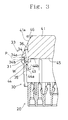
- the vertical wall face 44b of each engagement protrusion 44 is located at the distal end of the engagement groove 35 of the hood 30, as shown in FIG. 3.
- Each deformation preventing portion 43 then returns to its normal shape such that the engagement protrusions 43 invade the engagement grooves 35, engaging them, respectively.
- the locking arms 33 are located outside the respective deformation preventing portions 43 when the protecting cap 40 has been attached to the connector 10, as described above. Accordingly, each locking arm 33 abuts against the deformation preventing portion 43 when something strikes against the outer face of each locking arm during the transportation and a force acts on each locking arm 33 to cause it to be pushed inward. However, the locking arms 33 are held by the deformation preventing portions 44 from inside respectively such that each locking arm is prevented from flexing to such a degree that it cannot return to its normal shape.
- Two plate-shaped convex portions 46 are formed on each of upper and lower distal end corners of the protecting cap 40 so as to project outward.
- the height of each convex portion 46 is determined so that each convex portion 46 does not project from the outer periphery of the cap 40.
- Each convex portion 46 is formed to be inclined rearward. Since each convex portion 46 is formed into the shape of a plate, it has elasticity so as to deform forward and rearward. Since each convex portion 46 is inclined rearward, a force applied to it to deform rearward is smaller than a force applied to it to deform forward.
- the protecting cap 40 is designed not to project outward of the positioning ribs 32 and to pass through the mounting hole W of the panel P, as described above. Furthermore, since the distal end of the cap 40 is tapered, the distal end is sufficiently smaller than the mounting hole W such that it can be inserted into the mounting hole W readily. For example, holding the connector body 20 and abutting the distal end of the cap 40 against the panel P, the worker needs to fumble for the hole W when the hole cannot be viewed. Since the conventional protecting cap has the distal end whose configuration is substantially the same as that of the mounting hole, the protecting cap cannot be inserted into the mounting hole until the center position and the relative angle of the protecting cap correspond to those of the mounting hole.
- the distal end of the protecting cap 40 is tapered in the present embodiment, the distal end of the cap 40 can be easily inserted into the mounting hole W even when there is a positional shift between the cap and the hole.
- the inclined faces 41a and 41b slide on the edge of the mounting hole W as the cap 40 is further pushed into the hole.
- the positional shift is gradually corrected and the cap is accurately positioned.
- the convex portions 46 abut against the edge of the mounting hole when the distal end of the cap 40 is inserted into the hole.
- the convex portions 46 are formed partially on the distal end of the cap, the inserting work is not interrupted.
- each convex portion 46 has elasticity, it readily flexes even if it abuts against the edge of the mounting hole W. In particular, since each convex portion 46 can readily flex rearward, it does not cause any problem when the worker fumbles the mounting hole W and pushes the cap into the hole.
- the connector 10 Upon insertion of the distal end of the protecting cap, the connector 10 is gradually pushed into the mounting hole, so that any one of the inclined faces 41a, 41b of the lid portion 41 slides on the edge of the mounting hole, thereby guiding the protecting cap to its normal position as the connector is inserted into the mounting hole. Then, when the inclined faces 34a of the engagement protrusions 34 of the locking arms 33 abut against the edge of the mounting hole W, the edge of the mounting hole causes the locking arms 33 to flex inward. Since the upper and lower inclined faces 41a of the lid portion 41 are aligned with the inclined faces 34a of the engagement protrusions 34 respectively, the locking arms 33 do not abut against the edge of the mounting hole W but smoothly slide thereon.
- the protecting cap 40 is detached from the connector when the female connector is connected to the male connector. Since the inclined side faces 41b of the cap 40 are tapered, it is difficult to pull the cap out of the connector. However, since the convex portions 46 are formed on the corners of the upper and lower inclined faces 41b, the cap 40 can be held and pulled out easily when these convex portions afford hold for the fingers.
- FIGS. 4 to 6 illustrate a second embodiment of the invention.
- the deformation preventing portions also serve as the engagement members in the foregoing embodiment, the engagement members are formed on the mounting ribs formed on the side faces of the cap respectively.
- the flange 131 is formed on the whole outer periphery of the open end of the hood 130.
- the plate-like positioning ribs 132 project forward from the corners of the hood 130.
- the hood 130 has two arm holding chambers 133 formed in the upper and lower walls to extend longitudinally through the walls respectively. Each arm holding chamber 133 is inwardly bent such that the front end of the inner wall is lower than the outer wall thereof.
- Each arm holding chamber 133 has an engagement protrusion 133a formed on the rear portion of the inner wall to project outward.
- Each locking arm 134 is formed by bending a band-shaped metal plate. The front end of each locking arm 134 is folded rearward such that the engagement protrusion portion 134a is formed. The rear end of each locking arm 134 is folded forward such that an engagement hole 134b into which the engagement protrusion 133a can be inserted is formed.
- Each locking arm 134 is inserted into the arm holding chamber 133 from the end on which the engagement hole 134b is formed, and the engagement protrusion 133a is engaged with the engagement hole 134b, whereby each locking arm 134 is held in the arm holding chamber 133, as shown in FIG. 6. Since the front end of the inner wall of each arm holding chamber 133 is lowered inward relative to the outer wall thereof, the distal end of each locking arm 134 on which the engagement protrusion 134a is formed can readily flex into the hood 130.
- a part of the inner side wall of the hood 130 is inwardly raised so that a female screw section 135 with the female screw projecting toward the open end is provided.
- Engagement grooves 136 and ribs 137 guiding the female connector are formed in the upper and lower portions of each of the right-hand and left-hand side walls. Each engagement groove 136 is contiguous to the inside and outside of the hood 130.
- the protecting cap 140 includes the lid portion 141 formed into the shape of a dome so as to close the open end of the hood 130.
- the lid portion 141 includes the upper and lower inclined faces 141a and right-hand and left-hand inclined faces 141b such that the lid portion 141 has generally trapezoidal transverse and longitudinal sections.
- the protecting cap 140 is designed not to project outward of the positioning ribs 132 and to pass through the mounting hole W of the panel P.
- the upper and lower inclined faces 141a of the protecting cap 140 are located at the outer peripheral side relative to the distal ends of the locking arms 134.
- the cap 140 has positioning ribs 142 each projecting from an opening of the lid portion 141 along the inner peripheral face of the hood 130. Central portions of upper and lower walls of each positioning rib 142 are notched forward and the width of each notched portion is slightly larger than that of the locking arm 134. Unnotched portions of the upper and lower walls serve as the deformation preventing portions 143 respectively. The rib 144 reinforcing both deformation preventing portions 143 is formed to connect between the deformation preventing portions 143. A part of each positioning rib 142 is cut off so as not to interfere with the projecting portion formed on the side wall of the hood 130.
- the cap 140 has on the outer peripheral face of its distal end the engagement protrusions 145 formed to correspond to the respective engagement grooves 136 formed in the hood 130.
- a pair of engagement members are composed of the positioning ribs 142 and the engagement protrusions 145, respectively.
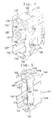
- FIG. 6 illustrates the state that the engagement protrusions 145 are in engagement with the respective engagement grooves 136. In this state, each deformation preventing portion 143 is inserted in the inside of the distal end of the locking arm 134 with a small gap therebetween.
- each locking arm 134 abuts against the deformation preventing portion 143 located inside when something strikes against the outer face of each locking arm 134 during the transportation such that a force pushing each locking arm 134 inward is applied thereto.
- each locking arm 134 can be prevented from flexing to such a degree that it cannot return to its normal shape.
- each locking arm 134 is slightly away from the outer face of the deformation preventing portion 143, and each positioning rib 142 is notched by the length corresponding to the width of the locking arm 134. Accordingly, each locking arm 134 can flex inward until its distal end abuts against the deformation preventing portion 143. Furthermore, the protecting cap 140 does not project outside the positioning ribs 132 of the connector 110. Accordingly, the connector 110 can be inserted into the mounting hole W of the panel P with the protecting cap 140 being attached thereto. Furthermore, since the distal end of the cap 140 is tapered, the distal end is sufficiently smaller than the mounting hole W such that the cap 140 can be readily inserted into the connector 110.
- the engagement protrusions 134a start smoothly contacting the edge of the mounting hole W when the inclined faces 141a, 141b positions the cap, sliding on the edge of the hole W. Accordingly, the locking arms 134 can flex inward.
- the distal end of the protecting cap 140 is tapered, the distal end of the cap 140 can be easily inserted into the mounting hole W even when there is a positional shift between the cap and the hole.
- the inclined faces 141a and 141b slide on the edge of the mounting hole W as the cap 140 is further pushed into the hole.
- the positional shift is gradually corrected and the cap is accurately positioned.
- the connector 110 Upon insertion of the distal end of the protecting cap, the connector 110 is gradually pushed into the mounting hole, so that any one of the inclined faces 141a. 141b slides on the edge of the mounting hole, thereby guiding the protecting cap to its normal position as the connector is inserted into the mounting hole.
- the locking arms 133 starts flexing inward, the positioning ribs 132 invade the mounting hole W to abut against the edge of the hole from inside, thereby positioning the connector 110.
- the engagement protrusions 134a are located at the opposite side of the panel P. Then, each locking arm 133 having flexed return to its normal shape, as shown in FIG. 6. Consequently, the panel P is held between the engagement protrusions 134 and the flange 131, and the locking arms 33 engage the panel P.
- each inclined face may be curved as shown in FIG. 7B.
Landscapes
- Connector Housings Or Holding Contact Members (AREA)
Claims (7)
- Kombination eines elektrischen Verbinders und einer dafür vorgesehenen Schutzkappe zur Anbringung an ein offenes Ende des elektrischen Verbinders (10; 110), wobei der elektrische Verbinder (10; 110) einen zylindrischen Abschnitt (30; 130) aufweist, in welchem eine Mehrzahl von Klemmen stehend angeordnet sind, die sich zum offenen Ende hin erstrecken, wobei der elektrische Verbinder ferner in einer Montageöffnung (W), welche in einem Paneel (P) ausgebildet ist, gehalten werden kann, so daß das offene Ende des zylindrischen Abschnitts (30; 130) der Montageöffnung (W) zugewandt ist, wobei die Schutzkappe (40; 140) einen Deckelabschnitt (41; 141) zur Abdeckung des offenen Endes des zylindrischen Abschnitts (30; 130) des Verbinders (10; 110) aufweist,
dadurch gekennzeichnet, daß
der Deckelabschnitt (41; 141) abgeschrägte Fronten (41a, 41b; 141a, 141b), welche jeweils eine konische Konfiguration in entgegengesetzter Richtung zum offenen Ende des zylindrischen Abschnitts (30; 130) aufweisen, und ein Paar von Eingriffselementen (42, 43; 142, 143) aufweist, welche den Deckelabschnitt (41; 141) an dem zylindrischen Abschnitt (30; 130) des Verbinders (10; 110) anbringen. - Kombination gemäß Anspruch 1, dadurch gekennzeichnet, daß jede abgeschrägte Front (41a, 41b) des Deckelabschnitts (41) einen konvexen Abschnitt (46) aufweist, dessen Höhe so bestimmt ist, daß sich dieser innerhalb eines äußeren Umfangs eines untersten Abschnitts des Deckelabschnitts (41) erstreckt, wobei der unterste Abschnitt einem konischen Ende des Deckelabschnitts (41) zugewandt ist.
- Kombination gemäß Anspruch 2, dadurch gekennzeichnet, daß jeder konvexe Abschnitt (46) eine derartige Elastizität aufweist, daß sich dieser in einer Richtung deformiert, in welcher der Verbinder (10) in die Montageöffnung (W) eingesetzt wird.
- Kombination nach Anspruch 3, dadurch gekennzeichnet, daß jeder konvexe Abschnitt (46) an der abgeschrägten Front (41a, 41b) stehend angeordnet ist, so daß er gegenüber der Richtung geneigt ist, in welcher der Verbinder (10) in die Montageöffnung (W) eingesetzt wird.
- Kombination nach Anspruch 1, dadurch gekennzeichnet, daß die Schutzkappe (40) ein Paar von Eingriffselementen (43) aufweist, welche sich jeweils zum offenen Ende des zylindrischen Abschnitts (30) des Verbinders (10) hin erstrecken, wobei sich jedes Eingriffselement (43), welches einen Eingriffsvorsprung (44) aufweist, in Umfangsrichtung erstreckt, und daß die abgeschrägten Fronten (41a, 41b), welche an der Schutzkappe ausgebildet sind, zumindest an der äußeren Umfangsseite relativ zu den distalen Enden der Eingriffselemente (43) angeordnet ist.
- Kombination nach Anspruch 1, dadurch gekennzeichnet, daß der Deckelabschnitt (41) in Form eines Kastens ausgebildet ist, und daß die abgeschrägten Fronten (41a, 41b) durch Kerben der distalen Enden der Eckbereiche des Deckelabschnitts (41) ausgebildet sind.
- Kombination gemäß Anspruch 2, dadurch gekennzeichnet, daß jede abgeschrägte Front (41a, 41b) eine bogenförmige Fläche aufweist.
Applications Claiming Priority (2)
| Application Number | Priority Date | Filing Date | Title |
|---|---|---|---|
| JP16910/93U | 1993-03-11 | ||
| JP1993016910U JP2567946Y2 (ja) | 1993-03-11 | 1993-03-11 | パネル取付コネクタ用保護キャップ |
Publications (3)
| Publication Number | Publication Date |
|---|---|
| EP0615314A2 EP0615314A2 (de) | 1994-09-14 |
| EP0615314A3 EP0615314A3 (en) | 1995-08-30 |
| EP0615314B1 true EP0615314B1 (de) | 1998-10-28 |
Family
ID=11929302
Family Applications (1)
| Application Number | Title | Priority Date | Filing Date |
|---|---|---|---|
| EP94103697A Expired - Lifetime EP0615314B1 (de) | 1993-03-11 | 1994-03-10 | Kombination eines in ein Paneel montierbaren elektrischen Verbinders und einer Schutzkappe |
Country Status (4)
| Country | Link |
|---|---|
| US (1) | US5480312A (de) |
| EP (1) | EP0615314B1 (de) |
| JP (1) | JP2567946Y2 (de) |
| DE (1) | DE69414156T2 (de) |
Families Citing this family (26)
| Publication number | Priority date | Publication date | Assignee | Title |
|---|---|---|---|---|
| DE4313285C1 (de) * | 1993-04-23 | 1994-04-21 | Hella Kg Hueck & Co | Gehäusekappe |
| US5746611A (en) * | 1996-07-15 | 1998-05-05 | The Whitaker Corporation | Electrical connector seal cap assembly |
| US6095852A (en) * | 1998-12-17 | 2000-08-01 | Yazaki North America, Inc. | Connector bracket wire shield with connector retention arms |
| US6454581B1 (en) * | 2000-12-28 | 2002-09-24 | Spx Corporation | Plug for covering a plurality of openings of an electronic device |
| US7165372B1 (en) * | 2004-12-10 | 2007-01-23 | Skulsky Bryan S | Pergola end cap method |
| TW529818U (en) * | 2002-05-24 | 2003-04-21 | Hon Hai Prec Ind Co Ltd | Connector protecting device |
| USD493773S1 (en) | 2003-02-18 | 2004-08-03 | Schweitzer Engineering Laboratories, Inc. | Connector cover |
| US7217146B2 (en) * | 2004-12-17 | 2007-05-15 | Scientific-Atlanta, Inc. | Connector insert for preventing contamination |
| JP4520315B2 (ja) * | 2005-01-21 | 2010-08-04 | タイコエレクトロニクスジャパン合同会社 | コネクタ用電線カバー |
| US7408469B2 (en) * | 2005-06-07 | 2008-08-05 | B&G Plastics, Inc. | Security device for electrical cord |
| DE102005026401B4 (de) * | 2005-06-08 | 2009-01-29 | Lapp Engineering & Co. | Mit einem Deckel verschließbares Winkelsteckverbindergehäuse |
| TWM299385U (en) * | 2006-01-20 | 2006-10-11 | Hon Hai Prec Ind Co Ltd | Electrical connector |
| WO2008073169A2 (en) * | 2006-08-31 | 2008-06-19 | The Trustees Of The University Of Pennsylvania | Methods, compositions and kits comprising attenuated anthrax vaccines and methods of delivery |
| US8853542B2 (en) | 2009-03-30 | 2014-10-07 | John Mezzalingua Associates, LLC | Collar for sealingly engaging a cover for cable connectors |
| US20120214335A1 (en) * | 2009-03-30 | 2012-08-23 | John Mezzalingua Associates, Inc. | Cover for cable connectors |
| US8764480B2 (en) | 2010-04-14 | 2014-07-01 | John Mezzalingua Associates, LLP | Cover for cable connectors |
| DE102011087615B4 (de) * | 2011-12-02 | 2025-10-02 | Te Connectivity Germany Gmbh | Kontakteinrichtungs-Schutzkappe sowie elektrische und/oder optische Einrichtung |
| USD805039S1 (en) * | 2015-01-29 | 2017-12-12 | Layer Zero Power Systems, Inc. | Cover |
| JP6324364B2 (ja) * | 2015-12-11 | 2018-05-16 | 矢崎総業株式会社 | コネクタのワイヤカバー |
| JP1604074S (de) * | 2017-07-20 | 2018-05-21 | ||
| JP1604551S (de) * | 2017-07-20 | 2018-05-21 | ||
| JP6916995B2 (ja) * | 2018-01-31 | 2021-08-11 | 住友電装株式会社 | 電線カバー及びコネクタ |
| EP3799222A1 (de) * | 2019-09-24 | 2021-03-31 | Aptiv Technologies Limited | Stecker, stiftabdeckung, system und verfahren zur bereitstellung eines steckers eines systems |
| US11458496B2 (en) * | 2020-11-07 | 2022-10-04 | Harry S. Audell | Foldable disposable protective cover for round gang boxes and lighting housings mounted in walls and ceilings of residential and commercial buildings |
| JP2022120628A (ja) * | 2021-02-05 | 2022-08-18 | 住友電装株式会社 | 車両用コネクタ |
| US12334671B2 (en) | 2022-10-19 | 2025-06-17 | Yazaki North America, Inc. | Retractable seal shroud |
Family Cites Families (13)
| Publication number | Priority date | Publication date | Assignee | Title |
|---|---|---|---|---|
| US2987690A (en) * | 1959-05-11 | 1961-06-06 | Victor D Marbais | Electrical wall outlet cover and guard |
| JPS54116694A (en) * | 1978-03-03 | 1979-09-11 | Yazaki Corp | Waterrproof connector |
| US4235502A (en) * | 1979-04-23 | 1980-11-25 | Amp Incorporated | Mounting means for mounting a connector in a panel |
| US4742541A (en) * | 1983-10-25 | 1988-05-03 | Northern Telecom Limited | Telecommunications interface with protector modules |
| US4541538A (en) * | 1984-04-16 | 1985-09-17 | General Electric Company | Wiring device covers |
| JPH01103283U (de) * | 1987-12-28 | 1989-07-12 | ||
| US5003128A (en) * | 1988-11-08 | 1991-03-26 | Yvan Grondin | Electrical switch and outlets protecting cover for painting |
| JPH0355263A (ja) * | 1989-07-13 | 1991-03-11 | Fuji Xerox Co Ltd | 荷電制御型インクジェットプリンタにおけるインク滴の帯電制御方式 |
| FR2656746B1 (fr) * | 1989-12-28 | 1992-04-03 | Telemecanique | Boitier de protection pour barres de distribution electrique. |
| JPH0754932Y2 (ja) * | 1990-07-09 | 1995-12-18 | 矢崎総業株式会社 | ネジ締めコネクタの防水構造 |
| JPH0587844A (ja) * | 1991-09-26 | 1993-04-06 | Toshiba Corp | 電源同期pll制御装置 |
| JPH0744079Y2 (ja) * | 1991-12-09 | 1995-10-09 | モレックス インコーポレーテッド | 表面実装用コネクタ自動マウント用カバー |
| US5285014A (en) * | 1991-12-11 | 1994-02-08 | Gayland Gilchrist | Paint shield for electrical outlets and switches |
-
1993
- 1993-03-11 JP JP1993016910U patent/JP2567946Y2/ja not_active Expired - Lifetime
-
1994
- 1994-03-10 US US08/208,278 patent/US5480312A/en not_active Expired - Lifetime
- 1994-03-10 EP EP94103697A patent/EP0615314B1/de not_active Expired - Lifetime
- 1994-03-10 DE DE69414156T patent/DE69414156T2/de not_active Expired - Lifetime
Also Published As
| Publication number | Publication date |
|---|---|
| JPH0670175U (ja) | 1994-09-30 |
| US5480312A (en) | 1996-01-02 |
| DE69414156T2 (de) | 1999-07-01 |
| EP0615314A3 (en) | 1995-08-30 |
| EP0615314A2 (de) | 1994-09-14 |
| JP2567946Y2 (ja) | 1998-04-08 |
| DE69414156D1 (de) | 1998-12-03 |
Similar Documents
| Publication | Publication Date | Title |
|---|---|---|
| EP0615314B1 (de) | Kombination eines in ein Paneel montierbaren elektrischen Verbinders und einer Schutzkappe | |
| US6165026A (en) | Terminal | |
| EP0615315B1 (de) | In ein Paneel montierbarer elektrischer Verbinder | |
| US5769650A (en) | Connector and cover therefor | |
| US5934944A (en) | Block connector | |
| EP1073153B1 (de) | Verbinder | |
| US5702021A (en) | Locking construction of electric connection box | |
| EP1091451B1 (de) | Verbinder | |
| JPH08321343A (ja) | 雌型端子金具 | |
| EP0902504B1 (de) | Verbinder mit Verriegelungsglied | |
| KR100326219B1 (ko) | 단자위치보장장치를갖는전기커넥터 | |
| EP0940883B1 (de) | Halterungsaufbau für einen Steckverbinder | |
| US5601449A (en) | Rear holder cover of waterproof connector | |
| EP0877447B1 (de) | Verbinder | |
| US5277603A (en) | Electric connector | |
| US7033205B2 (en) | Connector with a collision preventing projection | |
| EP0893850B1 (de) | Metallische Anschlussbuchse | |
| KR0149884B1 (ko) | 상자형 전장부품의 부착구조 | |
| EP0611867B1 (de) | Verbinder für Platten | |
| US5613878A (en) | Reverse insertion preventing connector | |
| US5520556A (en) | Female terminal | |
| EP1049210B1 (de) | Verschlusskappe für Verbinder | |
| JPH10270116A (ja) | コネクタ | |
| EP0910878B1 (de) | Elektrischer verbinder mit einstuckigem sekundaren verriegelungselement | |
| EP1156560A1 (de) | Elektrischer Kontakt für Birnenverbinder und Verbinder mit solchen Kontakten |
Legal Events
| Date | Code | Title | Description |
|---|---|---|---|
| PUAI | Public reference made under article 153(3) epc to a published international application that has entered the european phase |
Free format text: ORIGINAL CODE: 0009012 |
|
| AK | Designated contracting states |
Kind code of ref document: A2 Designated state(s): DE GB |
|
| PUAL | Search report despatched |
Free format text: ORIGINAL CODE: 0009013 |
|
| AK | Designated contracting states |
Kind code of ref document: A3 Designated state(s): DE GB |
|
| 17P | Request for examination filed |
Effective date: 19951102 |
|
| 17Q | First examination report despatched |
Effective date: 19970124 |
|
| GRAG | Despatch of communication of intention to grant |
Free format text: ORIGINAL CODE: EPIDOS AGRA |
|
| GRAG | Despatch of communication of intention to grant |
Free format text: ORIGINAL CODE: EPIDOS AGRA |
|
| GRAH | Despatch of communication of intention to grant a patent |
Free format text: ORIGINAL CODE: EPIDOS IGRA |
|
| GRAH | Despatch of communication of intention to grant a patent |
Free format text: ORIGINAL CODE: EPIDOS IGRA |
|
| GRAH | Despatch of communication of intention to grant a patent |
Free format text: ORIGINAL CODE: EPIDOS IGRA |
|
| GRAA | (expected) grant |
Free format text: ORIGINAL CODE: 0009210 |
|
| AK | Designated contracting states |
Kind code of ref document: B1 Designated state(s): DE GB |
|
| REF | Corresponds to: |
Ref document number: 69414156 Country of ref document: DE Date of ref document: 19981203 |
|
| PLBE | No opposition filed within time limit |
Free format text: ORIGINAL CODE: 0009261 |
|
| STAA | Information on the status of an ep patent application or granted ep patent |
Free format text: STATUS: NO OPPOSITION FILED WITHIN TIME LIMIT |
|
| 26N | No opposition filed | ||
| REG | Reference to a national code |
Ref country code: GB Ref legal event code: IF02 |
|
| PGFP | Annual fee paid to national office [announced via postgrant information from national office to epo] |
Ref country code: GB Payment date: 20020313 Year of fee payment: 9 |
|
| PG25 | Lapsed in a contracting state [announced via postgrant information from national office to epo] |
Ref country code: GB Free format text: LAPSE BECAUSE OF NON-PAYMENT OF DUE FEES Effective date: 20030310 |
|
| GBPC | Gb: european patent ceased through non-payment of renewal fee |
Effective date: 20030310 |
|
| PGFP | Annual fee paid to national office [announced via postgrant information from national office to epo] |
Ref country code: DE Payment date: 20110302 Year of fee payment: 18 |
|
| REG | Reference to a national code |
Ref country code: DE Ref legal event code: R119 Ref document number: 69414156 Country of ref document: DE Effective date: 20121002 |
|
| PG25 | Lapsed in a contracting state [announced via postgrant information from national office to epo] |
Ref country code: DE Free format text: LAPSE BECAUSE OF NON-PAYMENT OF DUE FEES Effective date: 20121002 |